This task requires a number of manipulations, which must be accompanied by a clear understanding of the principles and modes of operation of such equipment.
What it is and how it works
An asynchronous type electric motor is a machine in which electrical energy is transformed into mechanical and thermal energy. Such a transition becomes possible due to the phenomenon of electromagnetic induction that occurs between the stator and rotor windings. A feature of asynchronous motors is the fact that the rotation speed of these two key elements is different.
The design features of a typical electric motor can be seen in the illustration. Both the stator and the rotor are coaxial circular objects, made by assembling a sufficient number of plates from special steel. The stator laminations have grooves on the inside of the ring and, when aligned, form longitudinal grooves into which the copper wire winding is wound. For the rotor, its role is played by aluminum rods; they are also inserted into the grooves of the core, but are closed on both sides by locking plates.
When voltage is applied to the stator windings, an electromagnetic field appears on them and begins to rotate. Due to the fact that the rotor rotation speed is obviously lower, an EMF is induced between the windings and the central shaft begins to move. Non-synchronism of frequencies is associated not only with the theoretical foundations of the process, but also with the actual friction of the shaft support bearings; it will slow it down somewhat relative to the stator field.
What is an electric generator?
A generator is an electric machine that converts mechanical and thermal energy into electrical energy. From this point of view, it is a device directly opposite in principle of operation and mode of operation to an asynchronous motor. Moreover, the most common type of electric generators are induction.
As we remember from the theory described above, this becomes possible only when there is a difference in the revolutions of the magnetic fields of the stator and rotor. One logical conclusion follows from this (taking into account also the principle of reversibility, mentioned at the beginning of the article) - it is theoretically possible to make a generator from an asynchronous machine, in addition, this is a problem that can be solved independently by rewinding.
Engine operation in generator mode
Any asynchronous electric generator is used as a kind of transformer, where mechanical energy from the rotation of the motor shaft is converted into alternating current. This becomes possible when its speed becomes higher than synchronous (about 1500 rpm). The classic scheme for converting and connecting an engine in electric generator mode with the generation of three-phase current can be easily assembled with your own hands:
Our readers recommend! To save on electricity bills, our readers recommend the ‘Electricity Saving Box’. Monthly payments will be 30-50% less than they were before using the saver. It removes the reactive component from the network, resulting in a reduction in load and, as a consequence, current consumption. Electrical appliances consume less electricity and costs are reduced.

To achieve such a starting speed, it is necessary to apply a fairly large torque (for example, by connecting an internal combustion engine in a gas generator or an impeller in a windmill). As soon as the rotation speed reaches the synchronous value, the capacitor bank begins to operate, creating a capacitive current. Due to this, self-excitation of the stator windings occurs and electric current is generated (generation mode).
A necessary condition for the stable operation of such an electric generator with an industrial network frequency of 50 Hz is the compliance of its frequency characteristics:
- Its rotation speed must exceed the asynchronous speed (the operating frequency of the motor itself) by a slip percentage (from 2 to 10%),
- The generator rotation speed must match the synchronous speed.
How to assemble an asynchronous generator yourself?
Having acquired knowledge, ingenuity and the ability to work with information, you can assemble/remake a working generator from an engine with your own hands. To do this, you need to perform the exact steps in the following sequence:
- The real (asynchronous) rotation speed of the engine, which is planned to be used as an electric generator, is calculated. To determine the speed of a unit connected to the network, you can use a tachograph,
- The synchronous frequency of the motor is determined, which will also be asynchronous for the generator. Here the amount of slip is taken into account (2-10%). Let's say the measurements showed a rotation speed of 1450 rpm. The required operating frequency of the electric generator will be:
nGEN = (1.02…1.1)nDV= (1.02…1.1) 1450 = 1479…1595 rpm,
- Selection of a capacitor of the required capacity (standard comparative data tables are used).
We can put an end to this, but if a single-phase network voltage of 220V is required, then the operating mode of such a device will require the introduction of a step-down transformer into the previously given circuit.
Types of engine-based generators
Buying a standard ready-made electric generator is by no means a cheap pleasure and is unlikely to be affordable for the practical majority of our fellow citizens. A homemade generator can be an excellent alternative; it can be assembled with sufficient knowledge of electrical engineering and plumbing. The assembled device can be successfully used as:
- Self-powered electric generator. The user can obtain with his own hands a device for generating electricity with a long period of action due to self-recharge,
- Wind generator. A windmill, which rotates under the influence of the wind, is used as a propulsion device necessary to start the engine.
- Generator with neodymium magnets,
- Three-phase gas generator,
- Single-phase low-power generator for motors of electrical appliances, etc.
Converting a standard motor into a working generating device with your own hands is an exciting activity and obviously saves your budget. In this way, you can convert a regular windmill by connecting it to an engine for autonomous energy generation.
The basis was an industrial asynchronous AC motor with a power of 1.5 kW and a shaft speed of 960 rpm. By itself, such a motor cannot initially work as a generator. It needs improvement, namely replacement or modification of the rotor.
Engine identification plate:

The good thing about the engine is that it has seals everywhere it needs to be, especially at the bearings. This significantly increases the interval between periodic maintenance, since dust and dirt cannot easily get anywhere and penetrate.
The lamps of this electric motor can be placed on either side, which is very convenient.

Converting an asynchronous motor into a generator
Remove the covers and remove the rotor.The stator windings remain original, the motor is not rewound, everything remains as is, without changes.

The rotor was modified to order. It was decided to make it not all-metal, but prefabricated.

That is, the original rotor is ground down to a certain size.
A steel cup is turned out and pressed onto the rotor. The scan thickness in my case is 5 mm.

Marking the places for gluing the magnets was one of the most difficult operations. As a result, through trial and error, it was decided to print the template on paper, cut out circles in it for neodymium magnets - they are round. And glue the magnets according to the template onto the rotor.
The main snag arose in cutting out multiple circles in the paper.
All sizes are selected individually for each engine. It is impossible to give any general dimensions for the placement of magnets.

Neodymium magnets are glued with super glue.

A mesh of nylon thread was made for strengthening.

Next, everything is wrapped with tape, a sealed formwork is made from below, sealed with plasticine, and a filling funnel is made from the same tape on top. Everything is filled with epoxy resin.

The resin slowly flows down from top to bottom.

After the epoxy resin has hardened, remove the tape.


Now everything is ready to assemble the generator.

We drive the rotor into the stator. This must be done with extreme caution, since neodymium magnets have enormous strength and the rotor literally flies into the stator.

Assemble and close the lids.

The magnets don't touch. There is almost no sticking, it turns relatively easily.
Checking the work. We rotate the generator from a drill, with a rotation speed of 1300 rpm.
The engine is connected in a star; generators of this type cannot be connected in a triangle; they will not work.
The voltage is removed to check between phases.

The generator from an asynchronous motor works perfectly. For more detailed information, see the video.
Author's channel -
The article describes how to build a three-phase (single-phase) 220/380 V generator based on an AC asynchronous electric motor.
A three-phase asynchronous electric motor, invented at the end of the 19th century by the Russian electrical engineer M.O. Dolivo-Dobrovolsky, has now become predominantly widespread in industry, agriculture, and also in everyday life. Asynchronous electric motors are the simplest and most reliable to operate. Therefore, in all cases where this is permissible under the conditions of the electric drive and there is no need for reactive power compensation, asynchronous AC motors should be used.
There are two main types of asynchronous motors: with a squirrel cage rotor and with a wound rotor. An asynchronous squirrel-cage electric motor consists of a stationary part - the stator and a moving part - the rotor, rotating in bearings mounted in two motor shields. The stator and rotor cores are made of separate electrical steel sheets insulated from one another. A winding made of insulated wire is placed in the grooves of the stator core. A rod winding is placed into the grooves of the rotor core or molten aluminum is poured. Jumper rings short-circuit the rotor winding at the ends (hence the name short-circuited). Unlike a squirrel-cage rotor, a winding made like a stator winding is placed in the slots of a phase-wound rotor. The ends of the winding are brought to slip rings mounted on the shaft. Brushes slide along the rings, connecting the winding to a starting or control rheostat. Asynchronous electric motors with a wound rotor are more expensive devices, require qualified maintenance, are less reliable, and therefore are used only in those industries where they cannot be done without them. For this reason, they are not very common, and we will not consider them further.
A current flows through the stator winding connected to a three-phase circuit, creating a rotating magnetic field. The magnetic field lines of the rotating stator field cross the rotor winding bars and induce an electromotive force (EMF) in them. Under the influence of this EMF, current flows in the short-circuited rotor rods. Magnetic fluxes arise around the rods, creating a general magnetic field of the rotor, which, interacting with the rotating magnetic field of the stator, creates a force that forces the rotor to rotate in the direction of rotation of the stator magnetic field. The rotor rotation frequency is slightly less than the rotation frequency of the magnetic field created by the stator winding. This indicator is characterized by slip S and is for most engines in the range from 2 to 10%.
In industrial installations, three-phase asynchronous electric motors are most often used, which are produced in the form of unified series. These include the single 4A series with a rated power range from 0.06 to 400 kW, the machines of which are highly reliable, have good performance and meet world standards.
Autonomous asynchronous generators are three-phase machines that convert the mechanical energy of the prime mover into alternating current electrical energy. Their undoubted advantage over other types of generators is the absence of a commutator-brush mechanism and, as a consequence, greater durability and reliability. If an asynchronous motor disconnected from the network is set into rotation from any primary motor, then, in accordance with the principle of reversibility of electrical machines, when a synchronous rotation speed is reached, a certain EMF is formed at the terminals of the stator winding under the influence of a residual magnetic field. If you now connect a battery of capacitors C to the terminals of the stator winding, then a leading capacitive current will flow in the stator windings, which in this case is magnetizing. The battery capacity C must exceed a certain critical value C0, depending on the parameters of the autonomous asynchronous generator: only in this case does the generator self-excite and a three-phase symmetrical voltage system is installed on the stator windings. The voltage value ultimately depends on the characteristics of the machine and the capacitance of the capacitors. Thus, an asynchronous squirrel-cage electric motor can be converted into an asynchronous generator.
Fig. 1 Standard circuit for connecting an asynchronous electric motor as a generator.
You can select the capacitance so that the rated voltage and power of the asynchronous generator are equal to the voltage and power, respectively, when it operates as an electric motor.
Table 1 shows the capacitances of the capacitors for excitation of asynchronous generators (U=380 V, 750...1500 rpm). Here reactive power Q is determined by the formula:
Q = 0.314 U2 C 10 -6,
where C is the capacitance of the capacitors, μF.
|
Generator power, |
Idling |
|||||
|
capacity, |
reactive power, |
|||||
|
capacity, |
reactive power, |
capacity, |
reactive power, |
|||
As can be seen from the above data, the inductive load on the asynchronous generator, which reduces the power factor, causes a sharp increase in the required capacity.
To maintain a constant voltage with increasing load, it is necessary to increase the capacitor capacity, that is, connect additional capacitors.
This circumstance must be considered as a disadvantage of the asynchronous generator.
The rotation frequency of an asynchronous generator in normal mode must exceed the asynchronous one by a slip value S = 2...10%, and correspond to the synchronous frequency.
Failure to comply with this condition will lead to the fact that the frequency of the generated voltage may differ from the industrial frequency of 50 Hz, which will lead to unstable operation of frequency-dependent consumers of electricity: electric pumps, washing machines, devices with a transformer input.
A decrease in the generated frequency is especially dangerous, since in this case the inductive resistance of the windings of electric motors and transformers decreases, which can cause their increased heating and premature failure.
An ordinary asynchronous squirrel-cage electric motor of appropriate power can be used as an asynchronous generator without any modifications. The power of the electric motor-generator is determined by the power of the connected devices. The most energy-intensive of them are:
· household welding transformers;
· electric saws, electric jointers, grain crushers (power 0.3...3 kW);
· electric furnaces of the “Rossiyanka” and “Dream” types with a power of up to 2 kW;
· electric irons (power 850…1000 W).
I would especially like to dwell on the operation of household welding transformers.
Their connection to an autonomous source of electricity is most desirable, because when operating from an industrial network, they create a number of inconveniences for other electricity consumers. If a household welding transformer is designed to work with electrodes with a diameter of 2...3 mm, then its total power is approximately 4...6 kW, the power of the asynchronous generator to power it should be within 5...7 kW.
If a household welding transformer allows working with electrodes with a diameter of 4 mm, then in the heaviest mode - “cutting” metal, the total power consumed by it can reach 10...12 kW, respectively, the power of an asynchronous generator should be within 11...13 kW.
As a three-phase bank of capacitors, it is good to use so-called reactive power compensators, designed to improve cos φ in industrial lighting networks. Their typical designation: KM1-0.22-4.5-3U3 or KM2-0.22-9-3U3, which is deciphered as follows. KM - cosine capacitors impregnated with mineral oil, the first number is the size (1 or 2), then the voltage (0.22 kV), power (4.5 or 9 kvar), then the number 3 or 2 means three-phase or single-phase version, U3 (temperate climate of the third category).
In the case of self-manufacturing of the battery, you should use capacitors such as MBGO, MBGP, MBGT, K-42-4, etc. for an operating voltage of at least 600 V. Electrolytic capacitors cannot be used.
The option discussed above for connecting a three-phase electric motor as a generator can be considered classic, but not the only one. There are other methods that have proven themselves just as well in practice. For example, when a bank of capacitors is connected to one or two windings of an electric motor generator.
Fig.2 Two-phase mode of an asynchronous generator.
This circuit should be used when there is no need to obtain three-phase voltage. This switching option reduces the working capacity of the capacitors, reduces the load on the primary mechanical engine in idle mode, etc. saves "precious" fuel.
As low-power generators that produce an alternating single-phase voltage of 220 V, you can use single-phase asynchronous squirrel-cage electric motors for household use: from washing machines such as "Oka", "Volga", watering pumps "Agidel", "BTsN", etc. Their capacitor battery should connect parallel to the working winding. You can use an existing phase-shifting capacitor by connecting it to the working winding. The capacity of this capacitor may need to be increased slightly. Its value will be determined by the nature of the load connected to the generator: active loads (electric furnaces, light bulbs, electric soldering irons) require a small capacity, inductive loads (electric motors, televisions, refrigerators) require more.
Fig.3 Low-power generator from a single-phase asynchronous motor.
Now a few words about the primary mechanical engine, which will drive the generator. As you know, any transformation of energy is associated with its inevitable losses. Their value is determined by the efficiency of the device. Therefore, the power of a mechanical motor must exceed the power of an asynchronous generator by 50...100%. For example, with an asynchronous generator power of 5 kW, the power of a mechanical motor should be 7.5...10 kW. Using a transmission mechanism, the speed of the mechanical engine and the generator are matched so that the operating mode of the generator is set at the average speed of the mechanical engine. If necessary, you can briefly increase the generator power by increasing the speed of the mechanical engine.
Each autonomous power plant must contain the required minimum of attachments: an AC voltmeter (with a scale of up to 500 V), a frequency meter (preferably) and three switches. One switch connects the load to the generator, the other two switch the excitation circuit. The presence of switches in the excitation circuit makes it easier to start a mechanical engine, and also allows you to quickly reduce the temperature of the generator windings; after completion of work, the rotor of the unexcited generator is rotated for some time by the mechanical engine. This procedure extends the active life of the generator windings.
If, with the help of a generator, it is intended to power equipment that is normally connected to the alternating current network (for example, lighting of a residential building, household electrical appliances), then it is necessary to provide a two-phase switch that will disconnect this equipment from the industrial network while the generator is operating. Both wires must be disconnected: “phase” and “zero”.
In conclusion, some general advice.
The alternator is a hazardous device. Use 380 V only when absolutely necessary; in all other cases, use 220 V.
According to safety requirements, the electric generator must be equipped with grounding.
Pay attention to the thermal mode of the generator. He "does not like" idling. The thermal load can be reduced by more carefully selecting the capacitance of the exciting capacitors.
Make no mistake about the amount of electrical current produced by the generator. If one phase is used when operating a three-phase generator, then its power will be 1/3 of the total power of the generator, if two phases will be 2/3 of the total power of the generator.
The frequency of the alternating current produced by the generator can be indirectly controlled by the output voltage, which in the “no-load” mode should be 4...6% higher than the industrial value of 220 V / 380 V.
Literature:
L.G. Clothes textbook for rural electrician. M.: Agropromizdat, 1986.
A.A. Ivanov Handbook of Electrical Engineering. - K.: Higher School, 1984.
cm001.narod.ru
"Do it yourself" 2005, No. 3, pp. 78 - 82
It was decided to convert an asynchronous motor as a generator for a windmill. This modification is very simple and affordable, which is why in homemade wind generator designs you can often see generators made from asynchronous motors.
The modification consists of cutting the rotor under the magnets, then the magnets are usually glued to the rotor according to a template and filled with epoxy resin so that they do not fly off. They also usually rewind the stator with a thicker wire to reduce too much voltage and increase the current. But I didn’t want to rewind this motor and it was decided to leave everything as is, just convert the rotor to magnets. A three-phase asynchronous motor with a power of 1.32 kW was found as a donor. Below is a photo of this electric motor.
asynchronous motor conversion into a generator The rotor of the electric motor was machined on a lathe to the thickness of the magnets. This rotor does not use a metal sleeve, which is usually machined and placed on the rotor under the magnets. The sleeve is needed to enhance magnetic induction, through it the magnets close their fields by feeding each other from underneath and the magnetic field does not dissipate, but goes all the way to the stator. This design uses fairly strong magnets measuring 7.6*6mm in the amount of 160 pieces, which will provide a good EMF even without a sleeve.


First, before gluing the magnets, the rotor was marked into four poles, and the magnets were placed at a bevel. The motor was four-pole and since the stator did not rewound, there should also be four magnetic poles on the rotor. Each magnetic pole alternates, one pole is conventionally “north”, the second pole is “south”. The magnetic poles are made at intervals, so the magnets are grouped closer together at the poles. After being placed on the rotor, the magnets were wrapped with tape for fixation and filled with epoxy resin.
After assembly, the rotor felt sticking, and when the shaft rotated, sticking was felt. It was decided to remake the rotor. The magnets were knocked together with epoxy and placed again, but now they are more or less evenly placed throughout the rotor, below is a photo of the rotor with magnets before being filled with epoxy. After filling, the sticking decreased somewhat and it was noticed that the voltage dropped slightly when the generator rotated at the same speed and the current increased slightly.

After assembling the finished generator, it was decided to twist it with a drill and connect something to it as a load. A 220 volt 60 watt light bulb was connected, at 800-1000 rpm it burned at full intensity. Also, to test what the generator was capable of, a 1 kW lamp was connected; it burned at full intensity and the drill was not strong enough to turn the generator.

At idle, at maximum drill speed of 2800 rpm, the generator voltage was more than 400 volts. At approximately 800 rpm the voltage is 160 volts. We also tried connecting a 500-watt boiler, after a minute of twisting the water in the glass became hot. These are the tests that the generator, which was made from an asynchronous motor, passed.

Afterwards, a stand with a rotating axis was welded for the generator to mount the generator and tail. The design is made according to a scheme where the wind head is moved away from the wind by folding the tail, so the generator is offset from the center of the axis, and the pin behind is the pin on which the tail is placed.

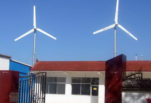
Here is a photo of the finished wind generator. The wind generator was installed on a nine-meter mast. When the wind was strong, the generator produced an idle voltage of up to 80 volts. They tried connecting a two-kilowatt tenn to it, but after a while the tenn became warm, which means the wind generator still has some power.

Then a controller for the wind generator was assembled and the battery was connected through it for charging. The charging current was quite good, the battery quickly began to make noise, as if it were being charged from a charger.
The data on the electric motor wiring diagram said 220/380 volts 6.2/3.6 A. This means the generator resistance is 35.4 Ohm delta/105.5 Ohm star. If he charged a 12-volt battery according to the scheme of connecting the generator phases in a triangle, which is most likely, then 80-12/35.4 = 1.9A. It turns out that with a wind of 8-9 m/s, the charging current was approximately 1.9 A, which is only 23 watt/hour, not much, but maybe I was wrong somewhere.
Such large losses are due to the high resistance of the generator, so the stator is usually rewound with a thicker wire to reduce the resistance of the generator, which affects the current strength, and the higher the resistance of the generator winding, the lower the current strength and the higher the voltage.
The energy of the electric current, entering the inside of an asynchronous motor, easily turns into motion energy at the exit from it. But what if a reverse transformation is required? In this case, you can build a homemade generator from an asynchronous motor. It will only function in a different mode: electricity will begin to be generated by performing mechanical work. The ideal solution is to transform it into a wind generator – a source of free energy.
It has been experimentally proven that a magnetic field is created by an alternating electric field. This is the basis of the operating principle of an asynchronous motor, the design of which includes:
- The body is what we see from the outside;
- Stator is the stationary part of the electric motor;
- A rotor is an element that is driven.
The main element of the stator is the winding, to which an alternating voltage is applied (the principle of operation is not on permanent magnets, but on a magnetic field that is damaged by alternating electric). The rotor is a cylinder with slots in which the winding is placed. But the current entering it has the opposite direction. As a result, two alternating electric fields are formed. Each of them creates a magnetic field, which begins to interact with each other. But the design of the stator is such that it cannot move. Therefore, the result of the interaction of two magnetic fields is the rotation of the rotor.
Design and principle of operation of the electric generator
Experiments also confirm that a magnetic field creates an alternating electric field. Below is a diagram that clearly illustrates the principle of operation of the generator.

If a metal frame is placed and rotated in a magnetic field, the magnetic flux penetrating it will begin to change. This will lead to the formation of an induced current inside the frame. If you connect the ends to a current consumer, for example, to an electric lamp, you can observe its glow. This suggests that the mechanical energy expended in rotating the frame within the magnetic field was converted into electrical energy, which helped light the lamp.
Structurally, an electric generator consists of the same parts as an electric motor: a housing, a stator and a rotor. The difference lies only in the principle of operation. The rotor is driven by the magnetic field created by the electric field in the stator winding. And an electric current appears in the stator winding due to a change in the magnetic flux penetrating it, due to the forced rotation of the rotor.
From electric motor to electric generator
Human life today is unthinkable without electricity. Therefore, power plants are being built everywhere, converting the energy of water, wind and atomic nuclei into electrical energy. It has become universal because it can be converted into the energy of movement, heat and light. This became the reason for the massive spread of electric motors. Electric generators are less popular because the state supplies electricity centrally. But still, sometimes it happens that there is no electricity and there is nowhere to get it from. In this case, a generator from an asynchronous motor will help you.
We have already said above that the electric generator and the engine are structurally similar to each other. This raises the question: is it possible to use this miracle of technology as a source of both mechanical and electrical energy? It turns out that it is possible. And we will tell you how to convert a motor into a current source with your own hands.
The meaning of the rework
If you need an electric generator, why make it from an engine if you can buy new equipment? However, high-quality electrical equipment is not a cheap pleasure. And if you have a motor that is not currently being used, why not put it to good use? With simple manipulations and at minimal cost, you will get an excellent current source that can power devices with active loads. These include computer, electronic and radio equipment, ordinary lamps, heaters and welding converters.
But savings are not the only advantage. Advantages of an electric current generator constructed from an asynchronous electric motor:
- The design is simpler than that of a synchronous analogue;
- Maximum protection of the insides from moisture and dust;
- High resistance to overloads and short circuits;
- Almost complete absence of nonlinear distortions;
- Clearance factor (a value expressing the uneven rotation of the rotor) no more than 2%;
- The windings are static during operation, so they do not wear out for a long time, increasing their service life;
- The generated electricity immediately has a voltage of 220V or 380V, depending on which engine you decide to convert: single-phase or three-phase. This means that current consumers can be directly connected to the generator, without inverters.
Even if the electric generator cannot fully meet your needs, it can be used in conjunction with a centralized power supply. In this case, we are again talking about saving: you will have to pay less. The benefit will be expressed as the difference obtained by subtracting the electricity generated from the amount of electricity consumed.
What is needed for remodeling?
To make a generator from an asynchronous motor with your own hands, you must first understand what is preventing the conversion of electrical energy from mechanical energy. Let us recall that for the formation of an induction current, the presence of a magnetic field that changes with time is necessary. When the equipment operates in motor mode, it is created in both the stator and the rotor due to power from the network. If you switch the equipment to generator mode, it turns out that there is no magnetic field at all. Where does he come from?
After the equipment operates in motor mode, the rotor retains residual magnetization. It is this force that causes an induced current in the stator due to forced rotation. And in order for the magnetic field to be maintained, it will be necessary to install capacitors that carry capacitive current. It is he who will maintain magnetization due to self-excitation.
We have sorted out the question of where the original magnetic field came from. But how to set the rotor in motion? Of course, if you spin it with your own hands, you can power a small light bulb. But the result is unlikely to satisfy you. The ideal solution is to turn the motor into a wind generator, or windmill.
This is the name given to a device that converts the kinetic energy of the wind into mechanical, and then into electrical. Wind generators are equipped with blades that move when they meet the wind. They can rotate in both vertical and horizontal planes.
From theory to practice
Let's build a wind generator from a motor with our own hands. For easy understanding, diagrams and videos are included with the instructions. You will need:
- Device for transmitting wind energy to the rotor;
- Capacitors for each stator winding.
It is difficult to formulate a rule according to which you could choose a wind catching device the first time. Here you need to be guided by the fact that when the equipment is operating in generator mode, the rotor speed should be 10% higher than when operating as an engine. You need to take into account not the nominal frequency, but the idle speed. Example: the rated frequency is 1000 rpm, and in idle mode it is 1400. Then to generate current you will need a frequency of approximately 1540 rpm.
The selection of capacitors by capacity is made according to the formula:
![]()
C is the required capacity. Q – rotor rotation speed in revolutions per minute. P is the number “pi” equal to 3.14. f – phase frequency (constant value for Russia, equal to 50 Hertz). U – network voltage (220 if one phase, and 380 if three).
Calculation example : Three-phase rotor rotates at 2500 rpm. ThenC = 2500/(2*3.14*50*380*380)=56 µF.
Attention! Do not select a container larger than the calculated value. Otherwise, the active resistance will be high, which will lead to overheating of the generator. This can also happen when the device is started without load. In this case, it will be useful to reduce the capacitance of the capacitor. To make it easy to do it yourself, place the container not as a whole, but as a prefabricated one. For example, 60 μF can be made up of 6 pieces of 10 μF connected in parallel to each other.
How to connect?
Let's look at how to make a generator from an asynchronous motor, using the example of a three-phase motor:
- Connect the shaft to a device that rotates the rotor using wind energy;
- Connect the capacitors in a triangle pattern, the vertices of which are connected to the ends of the star or the vertices of the stator triangle (depending on the type of connection of the windings);
- If a voltage of 220 Volts is required at the output, connect the stator windings in a triangle (the end of the first winding with the beginning of the second, the end of the second with the beginning of the third, the end of the third with the beginning of the first);
- If you need to power devices from 380 Volts, then a star circuit is suitable for connecting the stator windings. To do this, connect the beginning of all windings together, and connect the ends to the appropriate containers.


Step-by-step instructions on how to make a low-power single-phase wind generator with your own hands:
- Remove the electric motor from the old washing machine;
- Determine the working winding and connect a capacitor in parallel with it;
- Ensure that the rotor rotates using wind energy.

You will get a windmill, like in the video, and it will produce 220 Volts.
For electrical appliances powered by DC, an additional rectifier will be required. And if you are interested in monitoring the power supply parameters, install an ammeter and a voltmeter at the output.
Advice! Due to the lack of constant wind, wind generators may sometimes stop working or not work at full capacity. Therefore, it is convenient to organize your own power plant. To do this, the windmill is connected to the battery during windy weather. The accumulated electricity can be used during calm periods.
An electric motor is a device that acts as an energy converter and operates in the mode of obtaining mechanical energy from electrical energy. Through simple transformations without the use of a permanent magnet, but thanks to residual magnetization, the motor begins to work as a power source. These are two mutually inverse phenomena that help you save: you don’t need to buy a wind generator if you have an electric motor lying around. Watch the video and learn.