HV blocking generator (high voltage power supply) for experiments - you can buy it on the Internet or make it yourself. To do this, we need not very many parts and the ability to work with a soldering iron.
In order to assemble it you need:
1. Line scan transformer TVS-110L, TVS-110PTs15 from tube b/w and color TVs (any line scanner)
2. 1 or 2 capacitors 16-50V - 2000-2200pF
3. 2 resistors 27 Ohm and 270-240 Ohm
4. 1-Transistor 2T808A KT808 KT808A or similar characteristics. + good radiator for cooling
5. Wires
6. Soldering iron
7. Straight arms

And so we take the liner, disassemble it carefully, leave the secondary high-voltage winding, consisting of many turns of thin wire, a ferrite core. We wind our windings with enameled copper wire on the second free side of the ferite core, having previously made a tube around the ferite from thick cardboard.

First: 5 turns approximately 1.5-1.7 mm in diameter
Second: 3 turns approximately 1.1mm in diameter
In general, the thickness and number of turns can vary. I made what was at hand.
Resistors and a pair of powerful bipolar npn transistors - KT808a and 2t808a - were found in the closet. He did not want to make a radiator - due to the large size of the transistor, although later experience showed that a large radiator is definitely needed.

To power all this, I chose a 12V transformer; it can also be powered from a regular 12 volt 7A battery. from a UPS (to increase the output voltage, you can supply not 12 volts but, for example, 40 volts, but here you already need to think about good cooling of the trance, and the turns of the primary winding can be made not 5-3 but 7-5 for example).
If you are going to use a transformer, you will need a diode bridge to rectify the current from AC to DC, the diode bridge can be found in the power supply from the computer, you can also find capacitors and resistors + wires there.
As a result, we get 9-10 kV output.

I placed the entire structure in the PSU housing. It turned out to be quite compact.
So, we have an HV Blocking generator which gives us the opportunity to carry out experiments and run the Tesla Transformer.
It is not difficult to assemble a high-voltage generator at home; in this article we will look at a simple self-oscillator circuit, the distinctive features of which are simplicity and high output power.
A self-oscillator is a self-exciting system with feedback, which in turn ensures the maintenance of oscillations. In such a system, the frequency and shape of oscillations are determined by the properties of the system itself, and are not specified by external parameters.
The device diagram is presented below: 
 The device is a push-pull self-generating converter. Field-effect transistors VT1, VT2 are turned on alternately, for example, if transistor VT1 is turned on, the voltage at its drain decreases, diode VD4 opens, thereby the voltage at the gate of transistor VT2 decreases, preventing it from opening. Protective diodes VD2, VD3 protect the gates of transistors from overvoltage. The shape of the pulses on transformer T1 is close to sinusoidal.
 The main element of the circuit is the high-voltage transformer T1. Linear transformers (TVS) from Soviet-made tube black-and-white TVs are best suited. The magnetic core of such transformers is ferrite and consists of two U-shaped parts. The high-voltage secondary winding is made in the form of a solid plastic coil, as a rule, located separately from the block of primary windings. I used a magnetic core from a TVS-110L4 line transformer (magnetic permeability 3000NM), and removed the high-voltage winding from a TVS-110LA transformer. The original primary winding must be dismantled and a new one wound from enameled copper wire with a diameter of 2 mm, a total of 12 turns with a tap from the middle (6+6). During assembly, between the U-shaped parts of the magnetic circuit, at the junction, it is necessary to lay cardboard spacers, approximately 0.5 mm thick, to reduce saturation of the magnetic circuit.
 Inductor L1 is wound on a ferrite W-shaped magnetic core, 40-60 turns of enameled copper wire with a diameter of 1.5 mm, a 0.5 mm thick gasket is laid between the joints of the magnetic core. Ferrite rings or the U-shaped part of the magnetic circuit of a horizontal transformer can be used as a core.
 Capacitor C3 consists of 6 parallel-connected capacitors of the K78-2 brand 0.1 μm x 1000V, they are well suited for operation in high-frequency circuits. It is better to install resistors R1, R2 with a power of at least 2W. High-frequency diodes VD4, VD5 can be replaced with HER202, HER303 (FR202,303).
![]()
To power the device, an unstabilized power supply with a voltage of 24-36V and a power of 400-600W is suitable. I use an OSM-1 transformer (overall power 1 kW) with a rewound secondary winding of 36V.
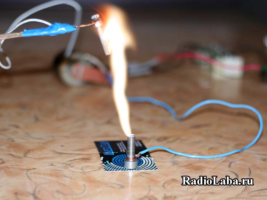
The electric arc is ignited from a distance of 2-3 mm between the terminals of the high-voltage winding, which approximately corresponds to a voltage of 6-9 kV. The arc turns out to be hot, thick and stretches up to 10 cm. The longer the arc, the greater the current consumed from the power source. In my case, the maximum current reached 12-13A at a supply voltage of 36V. To obtain such results, you need a powerful power source, in this case this is of primary importance.
 For clarity, I made a “Jacob’s ladder” from two thick copper wires, at the bottom the distance between the conductors is 2 mm, this is necessary for an electrical breakdown to occur, above the conductors diverge, the letter “V” is obtained, an arc is ignited at the bottom, heats up and rises up, where it breaks off. I additionally installed a small candle under the point of maximum approach of the conductors to facilitate the occurrence of breakdown. The video below demonstrates the process of arc movement along the conductors.

Using the device, you can observe a corona discharge that occurs in a highly inhomogeneous field. To do this, I cut out letters from foil and composed the phrase Radiolaba, placing them between two glass plates, and additionally laid a thin copper wire for electrical contact of all letters. Next, the plates are placed on a sheet of foil, which is connected to one of the terminals of the high-voltage winding, the second terminal is connected to the letters, as a result, a bluish-violet glow appears around the letters and a strong ozone smell appears. The foil cut is sharp, which contributes to the formation of a sharply inhomogeneous field, resulting in a corona discharge.
When one of the winding terminals is brought close to an energy-saving lamp, you can see an uneven glow of the lamp; here the electric field around the terminal causes the movement of electrons in the gas-filled bulb of the lamp. The electrons, in turn, bombard the atoms and transfer them to excited states; upon transition to the normal state, light is emitted.
The only drawback of the device is the saturation of the magnetic circuit of the horizontal transformer and its strong heating. The remaining elements heat up slightly, even the transistors heat up slightly, which is an important advantage; however, it is better to install them on a heat sink. I think even a novice radio amateur, if desired, will be able to assemble this self-oscillator and conduct experiments with high voltage.


The circuit is assembled on a blocking generator. You can install any n-p-n transistor: KT805, KT809A. Linear transformer TVS-110LA or TVS-110L6. There is also a multiplier. You can solder your own multiplier according to the circuit, or you can install a ready-made UN9/27 multiplier. Supply voltage 12-30 volts. Consumption 80 - 300 mA.
List of radio circuit components:
27 Ohm 2 W
220 - 240 Ohm 5-7 W
VT KT809A 

Transformer TVS-110LA or TVS-110L6
The primary winding is removed completely from the ferrite core and the other is wound on a cardboard frame with insulating tape, the first and second coils turn to the coil through a layer of insulating tape.
Winding L1 is a feedback winding and is wound with a wire of small diameter, it can be anything, for example, 0.2-0.3 mm. The number of turns of the communication winding can be selected, but there should be no more than 5 turns, because with a larger number, there is a risk of burning the transistor due to the relatively large induced voltage on the communication winding.
Winding L2 is working and is usually made with thick wire (0.5-1.5mm). The number of turns - the smaller, the greater the output voltage. But with fewer turns of this winding there is a risk of burning the transistor. The optimal number is 3-4 turns. These windings are located on the core and must be reliably isolated from it, because if there is a breakdown from the secondary to the core and high frequency high voltage hits any of the windings, you can kill the transistor with a 99% guarantee.
High-voltage, low-power generators are widely used in flaw detection, to power portable charged particle accelerators, X-ray and cathode ray tubes, photomultiplier tubes, and ionizing radiation detectors. In addition, they are also used for electric pulse destruction of solids, production of ultrafine powders, synthesis of new materials, as spark leak detectors, for launching gas-discharge light sources, in electric-discharge diagnostics of materials and products, obtaining gas-discharge photographs using the S. D. Kirlian method , testing the quality of high-voltage insulation. In everyday life, such devices are used as power sources for electronic ultrafine and radioactive dust collectors, electronic ignition systems, for electroeffluvial chandeliers (A.L. Chizhevsky chandeliers), aeroionizers, medical devices, gas lighters, electric fences, electric shock guns etc. .
Conventionally, we include devices that generate voltages above 1 kV as high-voltage generators.
The generator of high-voltage pulses using a resonant transformer (Fig. 11.1) is made according to the classical scheme using a gas spark gap RB-3.
Capacitor C2 is charged with a pulsating voltage through diode VD1 and resistor R1 to the breakdown voltage of the gas spark gap. As a result of breakdown of the gas gap of the spark gap, the capacitor is discharged onto the primary winding of the transformer, after which the process is repeated. As a result, damped high-voltage pulses with an amplitude of up to 3...20 kV are formed at the output of transformer T1.
To protect the output winding of the transformer from overvoltage, a spark gap made in the form of electrodes with an adjustable air gap is connected in parallel to it.
Rice. 11.1. Circuit of a high-voltage pulse generator using a gas spark gap

Rice. 11.2. Circuit of a high-voltage pulse generator with voltage doubling
Transformer T1 of the pulse generator (Fig. 11.1) is made on an open ferrite core M400NN-3 with a diameter of 8 and a length of 100 mm. The primary (low-voltage) winding of the transformer contains 20 turns of 0.75 mm MGShV wire with a winding pitch of 5...6 mm. The secondary winding contains 2400 turns of ordinary winding of PEV-2 wire 0.04 mm. The primary winding is wound on top of the secondary winding through a 2x0.05 mm polytetrafluoroethylene (fluoroplastic) gasket. The secondary winding of the transformer must be reliably isolated from the primary.
An embodiment of a high-voltage pulse generator using a resonant transformer is shown in Fig. 11.2. In this generator circuit there is galvanic isolation from the supply network. The mains voltage is supplied to the intermediate (step-up) transformer T1. The voltage removed from the secondary winding of the network transformer is supplied to a rectifier operating according to a voltage doubling circuit.
As a result of the operation of such a rectifier, a positive voltage equal to V2L/„ appears on the upper plate of the capacitor C2 relative to the neutral wire, where is the voltage on the secondary winding of the power transformer.
A corresponding voltage of the opposite sign is formed at capacitor C1. As a result, the voltage on the plates of the capacitor SZ will be equal to 2 V2L/„.
The charging rate of capacitors C1 and C2 (C1=C2) is determined by the value of resistance R1.
When the voltage on the plates of capacitor SZ becomes equal to the breakdown voltage of the gas gap FV1, a breakdown of its gas gap will occur, capacitor SZ and, accordingly, capacitors C1 and C2 will be discharged, and periodic damped oscillations will occur in the secondary winding of transformer T2. After discharging the capacitors and turning off the spark gap, the process of charging and subsequent discharging the capacitors to the primary winding of transformer T2 will be repeated again.
A high-voltage generator used to obtain photographs in a gas discharge, as well as to collect ultrafine and radioactive dust (Fig. 11.3) consists of a voltage doubler, a relaxation pulse generator and a step-up resonant transformer.
The voltage doubler is made using diodes VD1, VD2 and capacitors C1, C2. The charging chain is formed by capacitors C1 - C3 and resistor R1. A 350 V gas spark gap is connected in parallel to capacitors C1 - SZ with the primary winding of step-up transformer T1 connected in series.
As soon as the DC voltage level on capacitors C1 - SZ exceeds the breakdown voltage of the spark gap, the capacitors are discharged through the winding of the step-up transformer and as a result a high-voltage pulse is formed. The circuit elements are selected so that the pulse formation frequency is about 1 Hz. Capacitor C4 is designed to protect the output terminal of the device from mains voltage.
The output voltage of the device is entirely determined by the properties of the transformer used and can reach 15 kV. High voltage transformer for output

Rice. 11.3. Circuit of a high voltage pulse generator using a gas spark gap or dinistors
voltage of the order of ^0 kV is made on a dielectric tube with an outer diameter of 8 and a length of 150 mm; a copper electrode with a diameter of 1.5 mm is located inside. The secondary winding contains 3...4 thousand turns of PELSHO 0.12 wire, wound turn to turn in 10...13 layers (winding width 70 mm) and impregnated with EF-2 glue with interlayer insulation made of polytetrafluoroethylene. The primary winding contains 20 turns of PEV 0.75 wire passed through a polyvinyl chloride cambric.
As such a transformer, you can also use a modified horizontal scan output transformer of a TV; transformers for electronic lighters, flash lamps, ignition coils, etc.
The R-350 gas discharger can be replaced by a switchable chain of dinistors of the KN102 type (Fig. 11.3, right), which will allow the output voltage to be changed stepwise. To evenly distribute the voltage across the dinistors, resistors of the same value with a resistance of 300...510 kOhm are connected in parallel to each of them.
A variant of the circuit of a high-voltage generator using a gas-filled device - a thyratron - as a threshold-switching element is shown in Fig. 11.4.
The mains voltage is rectified by diode VD1. The rectified voltage is smoothed by capacitor C1 and supplied to the charging circuit R1, C2. As soon as the voltage on capacitor C2 reaches the ignition voltage of thyratron VL1, it

Rice. 11.4. High voltage pulse generator circuit using a thyratron
flares up. Capacitor C2 is discharged through the primary winding of transformer T1, the thyratron goes out, the capacitor begins to charge again, etc.
An automobile ignition coil is used as transformer T1.
Instead of the VL1 MTX-90 thyratron, you can turn on one or more KN102 type dinistors. The amplitude of the voltage can be adjusted by the number of switched on dinistors.
The design of a high-voltage converter using a thyratron switch is described in the work. Note that other types of gas-filled devices can be used to discharge a capacitor.
More promising is the use of semiconductor switching devices in modern high-voltage generators. Their advantages are clearly expressed: high repeatability of parameters, lower cost and dimensions, high reliability.
Below we will consider generators of high-voltage pulses using semiconductor switching devices (dinistors, thyristors, bipolar and field-effect transistors).
A completely equivalent, but low-current analogue of gas dischargers are dinistors.
In Fig. Figure 11.5 shows the electrical circuit of a generator made using dinistors. The structure of the generator is completely similar to those described earlier (Fig. 11.1, 11.4). The main difference is the replacement of the gas discharger with a chain of dinistors connected in series.

Rice. 11.5. Circuit of a high-voltage pulse generator using dinistors

Rice. 11.6. Circuit of a high-voltage pulse generator with a bridge rectifier
It should be noted that the efficiency of such an analogue and switched currents are noticeably lower than that of the prototype, however, dinistors are more affordable and more durable.
A somewhat complicated version of the high-voltage pulse generator is shown in Fig. 11.6. The mains voltage is supplied to the bridge rectifier using diodes VD1 - VD4. The rectified voltage is smoothed out by capacitor C1. This capacitor generates a constant voltage of about 300 V, which is used to power a relaxation generator composed of elements R3, C2, VD5 and VD6. Its load is the primary winding of transformer T1. Pulses with an amplitude of approximately 5 kBv\ repetition frequency up to 800 Hz are removed from the secondary winding.
The chain of dinistors must be designed for a switching voltage of about 200 V. Here you can use dinistors of the KN102 or D228 type. It should be taken into account that the switching voltage of dinistors of type KN102A, D228A is 20 V; KN102B, D228B - 28 V; KN102V, D228V - 40 V;
KN102G, D228G - 56 V; KN102D, D228D - 80 V; KN102E - 75 V; KN102Zh, D228Zh - 120 V; KN102I, D228I - 150 B.
As a T1 transformer in the above devices, a modified line transformer from a black and white TV can be used. Its high-voltage winding is left, the rest is removed and a low-voltage (primary) winding is wound instead - 15...30 turns of PEV wire with a diameter of 0.5...0.8 mm.
When choosing the number of turns of the primary winding, the number of turns of the secondary winding should be taken into account. It is also necessary to keep in mind that the value of the output voltage of the high-voltage pulse generator depends to a greater extent on the adjustment of the transformer circuits to resonance rather than on the ratio of the number of turns of the windings.
The characteristics of some types of horizontal scanning television transformers are given in table 11.1.
Table 11.1. Parameters of high-voltage windings of unified horizontal television transformers
|
Transformer type |
Number of turns |
R windings, Ohm |
||||
|
TVS-A, TVS-B |
||||||
|
TVS-110, TVS-110M |
||||||
|
Transformer type |
Number of turns |
R windings, Oi |
||||
|
TVS-90LTs2, TVS-90LTs2-1 |
||||||
|
TVS-110PTs15 |
||||||
|
TVS-110PTs16, TVS-11RPTs18 |
||||||

Rice. 11.7. Electrical circuit of a high-voltage pulse generator
In Fig. Figure 11.7 shows a diagram of a two-stage high-voltage pulse generator published on one of the sites, in which a thyristor is used as a switching element. In turn, a gas-discharge device - a neon lamp (chain HL1, HL2) was chosen as a threshold element that determines the repetition frequency of high-voltage pulses and triggers the thyristor.
When supply voltage is applied, the pulse generator, made on the basis of transistor VT1 (2N2219A - KT630G), produces a voltage of about 150 V. This voltage is rectified by diode VD1 and charges capacitor C2.
After the voltage on capacitor C2 precedes the ignition voltage of neon lamps HL1, HL2, the capacitor will be discharged through the current-limiting resistor R2 to the control electrode of thyristor VS1, and the thyristor will be unlocked. The discharge current of capacitor C2 will create electrical oscillations in the primary winding of transformer 12.
The thyristor switching voltage can be adjusted by selecting neon lamps with different ignition voltages. You can change the thyristor turn-on voltage stepwise by switching the number of neon lamps connected in series (or dinistors replacing them).

Rice. 11.8. Diagram of electrical processes on the electrodes of semiconductor devices (to Fig. 11.7)
The voltage diagram at the base of transistor VT1 and at the anode of the thyristor is shown in Fig. 11.8. As follows from the presented diagrams, the blocking generator pulses have a duration of approximately 8 ms. Capacitor C2 is charged exponentially in accordance with the action of pulses taken from the secondary winding of transformer T1.
Pulses with a voltage of approximately 4.5 kV are formed at the output of the generator. The output transformer for low-frequency amplifiers is used as transformer T1. As a high-voltage transformer T2, a transformer from a photo flash or a recycled (see above) horizontal scanning television transformer was used.
The diagram of another version of the generator using a neon lamp as a threshold element is shown in Fig. 11.9.

Rice. 11.9. Electrical circuit of a generator with a threshold element on a neon lamp
The relaxation generator in it is made on elements R1, VD1, C1, HL1, VS1. It operates with positive half-cycles of the mains voltage, when capacitor 01 is charged to the switching voltage of the threshold element on the neon lamp HL1 and thyristor VS1. Diode VD2 dampens self-induction pulses of the primary winding of step-up transformer T1 and allows you to adjust the output voltage of the generator. The output voltage reaches 9 kV. The neon lamp also serves as an indicator that the device is connected to the network.
The high-voltage transformer is wound on a piece of rod with a diameter of 8 and a length of 60 mm made of M400NN ferrite. First, the primary winding is placed - 30 turns of PELSHO 0.38 wire, and then the secondary winding - 5500 turns of PELSHO 0.05 or larger diameter. Between the windings and every 800... 1000 turns of the secondary winding, an insulation layer of polyvinyl chloride insulating tape is laid.
In the generator, it is possible to introduce discrete multi-stage adjustment of the output voltage by switching neon lamps or dinistors in a series circuit (Fig. 11.10). In the first version, two stages of regulation are provided, in the second - up to ten or more (when using KN102A dinistors with a switching voltage of 20 V).

Rice. 11.10. Electrical circuit of the threshold element

Rice. 11.11. Electrical circuit of a high voltage generator with a diode threshold element
A simple high-voltage generator (Fig. 11.11) allows you to obtain output pulses with an amplitude of up to 10.
The control element of the device switches with a frequency of 50 Hz (at one half-wave of the mains voltage). The diode VD1 D219A Shch220, D223) operating at reverse bias in avalanche breakdown mode was used as a threshold element.
When the avalanche breakdown voltage at the semiconductor junction of the diode exceeds the avalanche breakdown voltage, the diode transitions to a conducting state. The voltage from the charged capacitor C2 is supplied to the control electrode of the thyristor VS1. After turning on the thyristor, capacitor C2 is discharged onto the winding of transformer T1.
Transformer T1 does not have a core. It is made on a reel with a diameter of 8 mm from polymethylmethacrylate or polytetrachlorethylene and contains three spaced sections 9 mm wide. The step-up winding contains 3×1000 turns, wound with PET, PEV-2 0.12 mm wire. After winding, the winding must be soaked in paraffin. 2 - 3 layers of insulation are applied on top of the paraffin, after which the primary winding is wound - 3 × 10 turns of PEV-2 0.45 mm wire.
Thyristor VS1 can be replaced with another one for a voltage higher than 150 V. The avalanche diode can be replaced with a chain of dinistors (Fig. 11.10, 11.11 below).
The circuit of a low-power portable high-voltage pulse source with autonomous power supply from one galvanic element (Fig. 11.12) consists of two generators. The first is built on two low-power transistors, the second on a thyristor and a dinistor.

Rice. 11.12. Voltage generator circuit with low-voltage power supply and thyristor-dinistor key element
A cascade of transistors of different conductivities converts low-voltage direct voltage into high-voltage pulsed voltage. The timing chain in this generator is the elements C1 and R1. When the power is turned on, transistor VT1 opens, and the voltage drop across its collector opens transistor VT2. Capacitor C1, charging through resistor R1, reduces the base current of transistor VT2 so much that transistor VT1 comes out of saturation, and this leads to the closing of VT2. The transistors will be closed until capacitor C1 is discharged through the primary winding of transformer T1.
The increased pulse voltage removed from the secondary winding of transformer T1 is rectified by diode VD1 and supplied to capacitor C2 of the second generator with thyristor VS1 and dinistor VD2. In each positive half-cycle, storage capacitor C2 is charged to an amplitude voltage value equal to the switching voltage of dinistor VD2, i.e. up to 56 V (nominal pulse unlocking voltage for dinistor type KN102G).
The transition of the dinistor to the open state affects the control circuit of the thyristor VS1, which in turn also opens. Capacitor C2 is discharged through the thyristor and the primary winding of transformer T2, after which the dinistor and thyristor close again and the next capacitor charge begins - the switching cycle is repeated.
Pulses with an amplitude of several kilovolts are removed from the secondary winding of transformer T2. The frequency of spark discharges is approximately 20 Hz, but it is much less than the frequency of the pulses taken from the secondary winding of transformer T1. This happens because capacitor C2 is charged to the dinistor switching voltage not in one, but in several positive half-cycles. The capacitance value of this capacitor determines the power and duration of the output discharge pulses. The average value of the discharge current that is safe for the dinistor and the control electrode of the thyristor is selected based on the capacitance of this capacitor and the magnitude of the pulse voltage supplying the cascade. To do this, the capacitance of capacitor C2 should be approximately 1 µF.
Transformer T1 is made on a ring ferrite magnetic core of type K10x6x5. It has 540 turns of PEV-2 0.1 wire with a grounded tap after the 20th turn. The beginning of its winding is connected to transistor VT2, the end to diode VD1. Transformer T2 is wound on a coil with a ferrite or permalloy core with a diameter of 10 mm and a length of 30 mm. A coil with an outer diameter of 30 mm and a width of 10 mm is wound with PEV-2 0.1 mm wire until the frame is completely filled. Before winding is completed, a grounded tap is made, and the last row of wire of 30...40 turns is wound turn to turn over an insulating layer of varnished cloth.
The T2 transformer must be impregnated with insulating varnish or BF-2 glue during winding, then thoroughly dried.
Instead of VT1 and VT2, you can use any low-power transistors capable of operating in pulse mode. Thyristor KU101E can be replaced with KU101G. Power source - galvanic cells with a voltage of no more than 1.5 V, for example, 312, 314, 316, 326, 336, 343, 373, or nickel-cadmium disk batteries type D-0.26D, D-0.55S and so on.
A thyristor generator of high-voltage pulses with mains power is shown in Fig. 11.13.

Rice. 11.13. Electrical circuit of a high-voltage pulse generator with a capacitive energy storage device and a thyristor-based switch
During the positive half-cycle of the mains voltage, capacitor C1 is charged through resistor R1, diode VD1 and the primary winding of transformer T1. Thyristor VS1 is closed in this case, since there is no current through its control electrode (the voltage drop across diode VD2 in the forward direction is small compared to the voltage required to open the thyristor).
During a negative half-cycle, diodes VD1 and VD2 close. A voltage drop is formed at the cathode of the thyristor relative to the control electrode (minus - at the cathode, plus - at the control electrode), a current appears in the control electrode circuit, and the thyristor opens. At this moment, capacitor C1 is discharged through the primary winding of the transformer. A high voltage pulse appears in the secondary winding. And so - every period of mains voltage.
At the output of the device, bipolar high-voltage pulses are formed (since when the capacitor is discharged, damped oscillations occur in the primary winding circuit).
Resistor R1 can be composed of three parallel-connected MLT-2 resistors with a resistance of 3 kOhm.
Diodes VD1 and VD2 must be designed for a current of at least 300 mA and a reverse voltage of at least 400 V (VD1) and 100 B (VD2). Capacitor C1 type MBM for a voltage of at least 400 V. Its capacitance - fractions of a unit of microfarads - is selected experimentally. Thyristor VS1 type KU201K, KU201L, KU202K - KU202N. Transformer T1 - ignition coil B2B (6 B) from a motorcycle or car.
The device can use a horizontal scanning television transformer TVS-110L6, TVS-110LA, TVS-110AM.
A fairly typical circuit of a high-voltage pulse generator with a capacitive energy storage device is shown in Fig. 11.14.

Rice. 11.14. Scheme of a thyristor high-voltage pulse generator with a capacitive energy storage
The generator contains a quenching capacitor C1, a diode rectifier bridge VD1 - VD4, a thyristor switch VS1 and a control circuit. When the device is turned on, capacitors C2 and S3 are charged, thyristor VS1 is still closed and does not conduct current. The maximum voltage on capacitor C2 is limited by the zener diode VD5 with a value of 9 B. During the charging of capacitor C2 through resistor R2, the voltage on potentiometer R3 and, accordingly, on the control transition of thyristor VS1 increases to a certain value, after which the thyristor switches to a conducting state, and capacitor SZ through Thyristor VS1 is discharged through the primary (low-voltage) winding of transformer T1, generating a high-voltage pulse. After this, the thyristor closes and the process begins again. Potentiometer R3 sets the response threshold of thyristor VS1.
The pulse repetition rate is 100 Hz. An automobile ignition coil can be used as a high-voltage transformer. In this case, the output voltage of the device will reach 30...35 kV. The thyristor generator of high-voltage pulses (Fig. 11.15) is controlled by voltage pulses taken from a relaxation generator made on dinistor VD1. The operating frequency of the control pulse generator (15...25 Hz) is determined by the value of resistance R2 and the capacitance of capacitor C1.

Rice. 11.15. Electrical circuit of a thyristor high-voltage pulse generator with pulse control
The relaxation generator is connected to the thyristor switch through a pulse transformer T1 type MIT-4. A high-frequency transformer from the Iskra-2 darsonvalization apparatus is used as the output transformer T2. The voltage at the device output can reach 20...25 kV.
In Fig. Figure 11.16 shows an option for supplying control pulses to thyristor VS1.
The voltage converter (Fig. 11.17), developed in Bulgaria, contains two stages. In the first of them, the load of the key element, made on the transistor VT1, is the winding of the transformer T1. Rectangular control pulses periodically turn on/off the switch on transistor VT1, thereby connecting/disconnecting the primary winding of the transformer.

Rice. 11.16. Thyristor switch control option

Rice. 11.17. Electrical circuit of a two-stage high-voltage pulse generator
An increased voltage is induced in the secondary winding, proportional to the transformation ratio. This voltage is rectified by diode VD1 and charges capacitor C2, which is connected to the primary (low-voltage) winding of the high-voltage transformer T2 and thyristor VS1. The operation of the thyristor is controlled by voltage pulses taken from the additional winding of transformer T1 through a chain of elements that correct the shape of the pulse.
As a result, the thyristor periodically turns on/off. Capacitor C2 is discharged onto the primary winding of the high-voltage transformer.
Generator of high-voltage pulses, Fig. 11.18, contains a generator based on a unijunction transistor as a control element.
The mains voltage is rectified by the diode bridge VD1 - VD4. Smoothes out rectified voltage ripples

Rice. 11.18. Circuit of a high-voltage pulse generator with a control element based on a unijunction transistor
capacitor C1, the charge current of the capacitor at the moment the device is connected to the network is limited by resistor R1. Through resistor R4, capacitor S3 is charged. At the same time, a pulse generator based on a unijunction transistor VT1 comes into operation. Its “trigger” capacitor C2 is charged through resistors R3 and R6 from a parametric stabilizer (ballast resistor R2 and zener diodes VD5, VD6). As soon as the voltage on capacitor 02 reaches a certain value, transistor VT1 switches, and an opening pulse is sent to the control transition of thyristor VS1.
Capacitor 03 is discharged through thyristor VS1 to the primary winding of transformer T1. A high voltage pulse is formed on its secondary winding. The repetition rate of these pulses is determined by the frequency of the generator, which, in turn, depends on the parameters of the chain R3, R6 and 02. The tuning resistor R6 can change the output voltage of the generator by approximately 1.5 times. In this case, the pulse frequency is regulated within the range of 250... 1000 Hz. In addition, the output voltage changes when selecting resistor R4 (ranging from 5 to 30 kOhm.
It is advisable to use paper capacitors (01 and 03 - for a rated voltage of at least 400 V); The diode bridge must be designed for the same voltage. Instead of what is indicated in the diagram, you can use the T10-50 thyristor or, in extreme cases, KU202N. Zener diodes VD5, VD6 should provide a total stabilization voltage of about 18 B.
The transformer is made on the basis of TVS-110P2 from black and white TVs. All primary windings are removed and 70 turns of PEL or PEV wire with a diameter of 0.5...0.8 mm are wound onto the vacant space.
Electrical circuit of a high voltage pulse generator, Fig. 11.19, consists of a diode-capacitor voltage multiplier (diodes VD1, VD2, capacitors C1 - C4). Its output produces a constant voltage of approximately 600 V.

Rice. 11.19. Circuit of a high-voltage pulse generator with a mains voltage doubler and a trigger pulse generator based on a unijunction transistor
A unijunction transistor VT1 type KT117A is used as a threshold element of the device. The voltage at one of its bases is stabilized by a parametric stabilizer based on a VD3 zener diode of type KS515A (stabilization voltage 15 B). Through resistor R4, capacitor C5 is charged, and when the voltage at the control electrode of transistor VT1 exceeds the voltage at its base, VT1 switches to a conducting state, and capacitor C5 is discharged to the control electrode of thyristor VS1.
When the thyristor is turned on, the chain of capacitors C1 - C4, charged to a voltage of about 600...620 B, is discharged into the low-voltage winding of the step-up transformer T1. After this, the thyristor turns off, the charge-discharge processes are repeated with a frequency determined by the constant R4C5. Resistor R2 limits the short circuit current when the thyristor is turned on and at the same time is an element of the charging circuit of capacitors C1 - C4.
The converter circuit (Fig. 11.20) and its simplified version (Fig. 11.21) is divided into the following components: network suppression filter (interference filter); electronic regulator; high voltage transformer.

Rice. 11.20. Electrical circuit of a high voltage generator with a surge protector

Rice. 11.21. Electrical circuit of a high voltage generator with a surge protector
Scheme in Fig. 11.20 works as follows. The capacitor SZ is charged through the diode rectifier VD1 and resistor R2 to the amplitude value of the network voltage (310 B). This voltage passes through the primary winding of transformer T1 to the anode of thyristor VS1. Along the other branch (R1, VD2 and C2), capacitor C2 is slowly charged. When, during its charging, the breakdown voltage of dinistor VD4 is reached (within 25...35 B), capacitor C2 is discharged through the control electrode of thyristor VS1 and opens it.
Capacitor SZ is almost instantly discharged through the open thyristor VS1 and the primary winding of the transformer
T1. The pulsed changing current induces a high voltage in the secondary winding T1, the magnitude of which can exceed 10 kV. After the discharge of the capacitor SZ, the thyristor VS1 closes and the process repeats.
A television transformer is used as a high-voltage transformer, from which the primary winding is removed. For the new primary winding, a winding wire with a diameter of 0.8 mm is used. Number of turns - 25.
For the manufacture of barrier filter inductors L1, L2, high-frequency ferrite cores are best suited, for example, 600NN with a diameter of 8 mm and a length of 20 mm, each having approximately 20 turns of winding wire with a diameter of 0.6...0.8 mm.

Rice. 11.22. Electrical circuit of a two-stage high-voltage generator with a field-effect transistor control element
A two-stage high-voltage generator (author - Andres Estaban de la Plaza) contains a transformer pulse generator, a rectifier, a timing RC circuit, a key element on a thyristor (triac), a high-voltage resonant transformer and a thyristor operation control circuit (Fig. 11.22).
An analogue of the TIP41 transistor is KT819A.
A low-voltage transformer voltage converter with cross-feedback, assembled on transistors VT1 and VT2, produces pulses with a repetition frequency of 850 Hz. To facilitate operation when large currents flow, transistors VT1 and VT2 are installed on radiators made of copper or aluminum.
The output voltage removed from the secondary winding of transformer T1 of the low-voltage converter is rectified by the diode bridge VD1 - VD4 and charges capacitors S3 and C4 through resistor R5.
The thyristor switching threshold is controlled by a voltage regulator, which includes a field-effect transistor VT3.
Further, the operation of the converter does not differ significantly from the previously described processes: periodic charging/discharging of capacitors occurs on the low-voltage winding of the transformer, and damped electrical oscillations are generated. The output voltage of the converter, when used at the output as a step-up transformer of an ignition coil from a car, reaches 40...60 kV at a resonant frequency of approximately 5 kHz.
Transformer T1 (output horizontal scan transformer) contains 2×50 turns of wire with a diameter of 1.0 mm, wound bifilarly. The secondary winding contains 1000 turns with a diameter of 0.20...0.32 mm.
Note that modern bipolar and field-effect transistors can be used as controlled key elements.