It is not easy to build automatic gates yourself. Certain skills and knowledge are required. However, if you responsibly approach the work with your own hands, then the task is doable.
Automatic gate device
These gates are in increasing demand every day. Structures can be divided into 3 main groups:
- retractable automatic structures;
- hinged design with automation;
- automatic structures for garages.
Each type of gate has its own characteristics.
Sliding automatic structures are gates that are familiar to many and are used quite often.
Swing gates require free space on the side
It's all about cheapness and a simple device. The disadvantage is the need for free space for opening in the side parts.
The frame is most often made of a rigid metal profile. Next, the structure will need to be sheathed. Sheathing can be made of wood or metal. Another option is to use forged carved gratings for sheathing gates.
The design consists of the following elements:
- gate leaves;
- fixing supports;
- a set of loops;
- bolt;
- one or more drives;
- opening handles;
- elements for side stop;
- center stop;
- brackets for fixing the electric drive to the supports and sashes.
Mandatory design details are lateral and central stops. These are limiters that will not allow the valves to go beyond certain limits. Stops can be fixed or removable.
Mandatory details of the design also include handles and a deadbolt.
Elements needed in case of power outage
In the event of an electrical problem, the gate can only be locked and unlocked manually. The actuator comes with these parts. It is undesirable to purchase separately, as the elements may not be compatible with each other.
According to the device, automation can be divided into:
- a drive that performs the operations of opening and closing the valves with fixing the required position;
- automation that controls the operation of the main parts of the drive mechanism.
All moving parts must move freely along the guides. The owner must periodically control them. It is important to regularly clean and lubricate the moving parts of the structure. If the leaves are difficult to move, then there may be an increase in the load on the drive and the electric motor. In this case, mechanical failures may occur.
Retractable design
The drive consists of the following elements:

Each type of gate requires an individual drive that can provide a certain type of device movement over the required distances.
Swing construction
According to the principle of operation, they are divided into:
- Lever. Consist of a set of blocks with levers.
Lever drive gate
- Linear. Fixed at one point. The moving bracket moves in a straight line inside the case. The most commonly used is turning a screw through a nut, gears with a chain or belts.
Linear drive for automatic gates
- Hydraulic. They are used for heavy structures, the weight of the leaves of which is 950 kg or more. The required leaf width is from 4.5 m. The elements will be subjected to intensive use.
Hydraulic drive is necessary for structures that are subjected to heavy loads
- Telescopic. The elements are divided into sections. The design consists of internal sliders that allow the sections to move apart to move the end holder.
Telescopic drive for automatic gates
The drive must be firmly fixed to the base. Distortions and gaps during the operation of mechanisms are not allowed, therefore, the deepening of the base under the gate and automatic devices should be greater than the level of ground freezing in winter. Only in this way can the high-quality functioning of the gate be guaranteed.
In order for the automatic control of the functioning of the leaves to take place reliably, all devices must be debugged and checked manually. These works are carried out at the final stage of construction work. Automatic mechanisms can work:
- Remotely. Based on the transmission of commands via radio waves from the remote control to the receiving device, which controls the operation of the electric motor and other parts.
- From a stationary remote control, which is located on the wall of a private house.
- From a combination of the first two options.
Remote control is based on the same principles as for a permanently mounted remote control with ordinary on and off buttons for a simple electric motor. The difference is that in this case it is possible to solve auxiliary technical problems.
The principle of operation of automation
First of all, the method of operation of automation from the remote control will be considered. In this case, a slight addition to the previous scheme is used. It consists in connecting in parallel with the control keys of the electronic key. It works from the signals of the receiving device, which receives commands via radio waves from the transmitter in the form of a remote control. The devices are presented in a wide range and may have different functionality and appearance, but the principle of operation remains the same.
The placement of control sensors and power mechanism components will depend on the design of the gate and the conditions of the region. For example, you can implement automatic sliding gates according to the following scheme:
You can implement automation in swing gates according to this scheme
Photocells will control the quality of the work surface. To do this, they will need to be mounted on posts fixing racks, walls and supports. After that, they need to be configured so that they can clearly cover the entry zones, control the doors reaching the extreme positions and exclude them from hitting people, cars or animals that may suddenly appear.
The drive of each of the leaves must be installed on the supporting parts.
The drive must be placed on the inside of the yard
The key to disable the structure is located on the inside of the wall near the gate.
A signaling lamp is needed to illuminate the roadway.
A signal lamp is needed to notify the opening of the gate
The device for receiving signals from the transmitter, which is located in the control unit, together with a separate drive, is fixed to the rack support. Near it, you should place a closed terminal box with wires that connect the system components to a fixed console and an input shield with a protective coating.
Electrical wiring must be hidden in special channels and protected from unforeseen damage. The command transmitter, which is built into the console, can be controlled by pressing the keys on the case.
You can control the gate with the remote control
As a result, the transmitter will broadcast encrypted radio signals of the set frequency through the antenna, which can only be perceived by the receiving device inserted into the main control unit.
After processing, the received commands are sent to the key and executed. Then the circuit will work in the same way as in the case of a fixed control unit.
For the convenience of working with the remote control, it is recommended to pre-configure the device for various algorithms. For example, you can open or close the gate leaves by single or double pressing on the control button. To do this, the receiving device and transmitter will need to be turned on and programmed according to a certain algorithm for pressing buttons on a configured mechanism. Electronics will remember this sequence of actions and will follow it in the future.
The system can be integrated with the ability to disable the operation of the automatic mechanism so that the gate is operated only manually. A manual lock and lock key must be used to complete the task. Parts must be placed in a place convenient for operation, but inaccessible to unauthorized persons.
If it is planned to manufacture automatic sliding gates, then the locations of the drive and automation devices are somewhat different, but the principle of operation remains unchanged. It will only be necessary to take into account the conditions of the design, the region and the requests of the owner of a private house. For a sliding sash, you only need to place 2 safety photocells. The stop of the drive can be provided by end mechanical devices for switching off.
All automation schemes provide a system for repeating specified processes. It allows redundant protection functions. For example, in the event of a failure of the limit switch to suspend the leaves, the motor overload protection should work. As a result, the drive will stop working. This prevents damage to the entire system.
Preparation for construction: drawings and diagrams
Installation of automatic gates should begin with drawing up a drawing. Using a pencil on a sheet of paper, draw a diagram of the gate, taking into account the dimensions. It is desirable to indicate the main dimensions of the parts on the diagram.
The dimensions of the automatic design must be specified as accurately as possible. During the calculation, the following requirements must be observed:
- when a vehicle enters the garage, at least 30 cm must remain on each side;
- the higher this indicator, the easier it will be to enter the territory of the site;
- the width must be determined taking into account the type of vehicle.
For an ordinary passenger car, a width of 2.5 m and a height of 2 m are enough. For a minibus, the height should be about 2.5 m.
From the standard swing design, the automatic one differs only in the presence of a drive. At this stage, you should decide on the type of device - lever or linear will be installed. If you plan to install sliding gates, then the drive with levers is most often used. Linear is set if there is a minimum distance from the extreme part of the support to the loop. If there is a gap of more than 15 cm, then it is advisable to use a lever device.
Automation installation diagram indicating the number of cable cores and their cross sections
Sliding gates will be affected by the wind load, so it is important to take care of protecting the devices in advance.
If you plan to install automatic garage doors, then the ceiling level must be lowered by 25 cm. This should be taken into account, since installation will require space under the ceiling structure.
The scheme of the retractable automatic design is practically no different.
The layout of the elements of automatic sliding gates
In this case, only one electric motor will be needed.
Having decided to carry out the installation of automation, the owner of a private house assumes that it will serve for decades. A high-quality set can function for many decades, but low-quality components can become an unnecessary “headache”. To make the right choice, you should consider the following recommendations:
Manufacturer selection
Today, in construction supermarkets, you can find automation from Chinese and European factories. Chinese devices are aimed at a significant reduction in cost at the expense of quality, but there are exceptions. Well-known Chinese companies offer high-quality products for the automation of various types of gates.
From European manufacturers, Italian and German fittings should be preferred, but the latter is more expensive. Regardless of which manufacturer is chosen, you should not buy cheap parts that no one has heard of. Automatic mechanisms are purchased for a long time, so you should not save on it.
Gate drive selection
The best option can be recommended by an automation installation specialist, however, you need to understand this issue yourself. As mentioned earlier, the drive can be worm or lever. The choice must first of all be made based on preferences for the appearance of the product. You should also consider in which direction the structure will open - into the yard or the roadway.
The worm drive is easy to install, easy to maintain and has a long service life. This type of mechanism can be installed on gates that open both inside and outside the building. If the structure opens outward, then there are limitations: the gate opening will decrease by approximately 30 cm. This is due to the installation features. If there is no free space, then such a drive is not suitable.
With the help of a drive with levers, gates opening into the territory are automated.
The lever drive can only open the gate inward
The lever mechanism is more perfect in terms of manufacturability. The disadvantage is the high cost.
Accordingly, if the gate will open inside the territory, then you can choose a drive of any type. If outward, then only a worm gear is allowed.
Drive power selection
In the process of choosing automatic mechanisms, the weight of the wings must be taken into account. The technical documentation indicates how much the device is designed for. It is recommended to mount an electric drive that is designed for more weight. The recommended power margin is 30%. If the device is operated at its power limit, the drive will overheat. This will lead to the failure of the mechanism earlier than the period declared by the manufacturer.
Wind load should also be taken into account. If the gate consists of a single leaf, then the drive will have to overcome the effect of the wind. Accordingly, a more powerful design is required.
Another problem is climate change in cold weather. In summer, the design can easily open a gate weighing 250 kg, but in winter, difficulties may arise, since the drive will operate in labor-intensive conditions. Be sure to take into account that in some regions during this period the voltage of the mains drops. Drives without a power reserve may not start in this case.
Availability of additional functions
Manufacturers produce a wide range of accessories. Be sure to purchase photocells that help stop the process of closing the gate if obstacles appear in the coverage area:
It is also recommended to purchase an antenna that can increase the range of the remote control. Signal lamps can warn others that the gate is open. This function will be needed if the exit goes to the sidewalk on which people walk.
The choice of additional options depends on the operating conditions of the door.
It is also important to take into account the technical parameters that are used to classify automatic mechanisms:
- Torque (Nm) - the basic parameter of automation for a lever swing structure. This characteristic is not used for worm automatics. Torque can show how much weight the design can open the actuator. The higher the indicator, the more the weight of the valves can open the automatic mechanism. For doors weighing up to 800 kg, the optimum torque is 3000 Nm.
- Intensity (%) - a parameter that shows the maximum intensity of the use of the electric motor. The intensity is the ratio of the period of operation of the device to the total time. For example, if the parameter is 30%, then the structure can work 30% of the time, while the break in work will be 70% of the time. Usually this value is sufficient for gates with standard parameters.
- Traction force (N) - the parameter will show with what force the mechanism presses on the leaves. The larger the characteristic, the more powerful the drive. The optimal value for a 6 m gate is 400 N.
The parameter of the maximum weight of the sash should not be taken into account. The choice must be made on the basis of tractive effort and torque.
Calculation of materials and list of tools
The minimum set of automation includes the following elements:
- rack;
- limit switches;
- electric drive.
- photocells;
- warning lamp;
- remote antenna.
Laying a cable with a voltage of 220 V on the territory of a private house underground can be performed without additional protection of the wire from damage. Under the passage of the car, additional cable protection must be used. In this place, the wire must be laid in a case. The structure can be built from a metal or plastic pipe. The depth of the wire laying is 0.8–1.2 m.
Underground cable laying is best done in technical HDPE pipes
Such pipes cost 2 times lower than standard ones, since they cannot withstand the same pressure that ordinary water pipes can withstand. For laying the electrical cable, pipes with a thickness of 3 mm will suffice.
To bend pipes at an angle, fittings, reducers and flanges are needed.
Cable laying underground and connecting pipes with fittings
It is important to know the typology of wires and their minimum cross section:
The antenna is connected using a RG58 coaxial wire with a characteristic impedance of 50 ohms.
If you plan to install an additional intercom near the gate, then from the private house to the structure you need to lay 2 two-wire wires 2x0.5 mm² or 2x0.75 mm².
Sliding gate materials
For the installation of an automatic sliding structure, you must also prepare the following elements:
- bicycle carriages;
Bicycle carriages can be used in automatic gates
- flaps;
- top support rollers;
Top rollers for gates
- guide bar;
- rolling rollers;
roller for gates
- several traps;
Gate catcher
- jack;
- coating material (profiled or iron sheets, polycarbonate or wood);
- channel;
- brick.
You also need to prepare an unused washing machine, some elements will be needed for automation.
Sliding Gate Materials
For automatic gates of this type, it is necessary to prepare the following elements:
- reinforced hinges with bearings;
- handles;
- central and side stops;
- valve;
- washing machine;
- coating material;
- profile pipes;
- bicycle carriages.
Unlike the retractable design, in this case you will need 2 electric motors.
To build a sliding or sliding gate drive, you will need to prepare several carriages with asterisks.
Geared motors of various types can be used as motion activators. If you plan to install small gates with low weight, then a battery-powered screwdriver electric motor, a drive for a car glass cleaner or window lifter will do.
You will also need to resolve the issue with the clutch for the shafts of electric motors. To do this, determine the required torque. For example, the closing force of the flaps can be 13.5 kg. Each kg corresponds to 9.8 N. Accordingly, the traction force will be 132.3 N. This value must be divided by the diameter of the drive wheel.
You will need these tools:
- electric drill;
- insulating tape;
- pliers;
- meter;
- a hammer;
- soldering iron;
- screwdriver.
Step-by-step guide to making gate automation
There are many options for making a drive with your own hands from various materials.
How to build a drive for sliding gates?
You can make a drive from two carriages. You will need to do the following:
- The frame must be cut so that the vertical pipe that comes from the axis protrudes a few cm above the star.
- On the one hand, it is necessary to dismantle the pedal, and on the other hand, remove the pedal and connecting rod.
- There should be 2 sprockets. Their dimensions and tooth pitch should be the same, since the drive will use a single chain.
- The carriages must be welded to the top of the frame. Stars that are placed at the corners should be placed parallel to each other.
- The connecting rods should be positioned a short distance from the frame.
- The rods that connect the connecting rods with the gate are recommended to be selected in accordance with the dimensions of the stars.
- When the stars move, the bar that connects the sashes to the connecting rods will move the canvas.
- It is problematic to choose the exact length of the rod, as there are various models of bicycles. Suitable design with a diameter of M-8. The bar can be made from a metal strip.
- The chain must be crossed over the stars. As a result, they should scroll in different directions. The design is made of several chains from a bicycle. They will need to be fastened to each other.
- It is important to tighten the chain well. However, this will not solve the problem that it may sag or come off. This can only be fixed by welding a few steel strips to the frame to support the chain. Details will be used as guides. Another option is to fix the large width rollers along which the chain will move.
Homemade drive for gates from a bicycle frame assembly
The chain is mounted exclusively on closed gates. After that, a design check should be performed. To do this, you need to push out one sash. The second will have to move symmetrically to the first. If overlap is obtained, then the chain should be moved one tooth.
How to make a sliding gate drive?
The lightweight sash can be driven by a drive from a modernized power window mechanism. The advantages of the method include ease of manufacture and operation with virtually no noise. The following power windows can be used as a drive:
- a drive that functions with a gear;
- a design in which a rack with teeth is used as a moving element.
In each case, the drive part must be installed on an iron platform, which is securely attached to the pole. The metal bar should move parallel to the base of the gate and extend towards it.
The power window mechanism needs to be improved:

Automation for sliding and sliding gates
The next step is to mount the motor for the sliding gate.
After manufacturing the drive, you will need to install the automation for the gate
To open the gate, you need to push one leaf or pull the chain towards you. To automate the design, you can install an electric motor and connect it to the gearboxes from the car wipers.
The electric motor will need to be connected to the gearboxes of the car wipers
An old battery can be used as a power source. Due to this device, automation will not depend on electricity. The disadvantage of the old battery is that it will open the doors slowly.
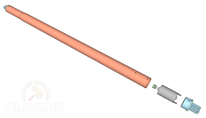
Another option is to use an electric motor from a washing machine. The average power of the device is 105–115 W, the scrolling speed is 1500 rpm. A screw jack for passenger vehicles can be used as a gearbox. The jack will need to be improved. To do this, behind the bevel gear, you need to install a pulley from the washing machine. In this way, you can turn the jack into a linear gearbox.
The jack must be welded parallel to the chain so that during movement the slider pulls the chain. Iron wire is used to fasten the parts together.
It is important to know: if the electricity is turned off, you will have to unwind the wire each time to open the gate.
To connect the electric motor to the pulley, you will need a belt from a washing machine. The motor speed will be reduced approximately 1:4, so the pulley diameter should be as small as possible.
To remotely control the gate, you will need to buy a single-channel 12 V car alarm and connect it.
You can connect the radio control using a car alarm according to this scheme
Automation for sliding gates consists of the same elements. The only difference is that you need 2 electric motors. They are located in the side parts of the gate. You will also need to install levers. You can make them from a profile pipe.
How to set up automation?
Each mechanism has its own characteristics. In order for the design to serve for a long time, you will need to correctly program the control apparatus. Different manufacturers have different settings, but the following settings are most often configured:
- current sensitivity. The parameter is responsible for starting the protective device. If there is an obstacle, the gate stops.
- Speed change. The speed of movement of the leaves can be changed by reducing or increasing the power of the electric motor. It is not recommended to set a fast tempo, as this can lead to equipment failure. To increase the speed, you can increase the voltage to 38 V.
- Automatic closing. To implement this function, the design must provide for the presence of a timer. The part is best purchased in finished form.
Other functions can be implemented by adding appropriate details to the design diagram.
In order for these gates to serve for a long time, you need to adhere to the following tips for use:
- Mechanisms need to be serviced from time to time. The process consists in lubricating moving parts. Only non-freezing grease may be used.
- Periodically, the guides should be inspected and cleaned of debris. If ice forms, the canvas may jam.
- Automation mechanisms are also subject to verification. Parts should be checked at least once a year. If any of the elements is out of order, it is recommended to entrust the repair to specialists.
- You have to take care of the fabric. It has an anti-corrosion coating, but it is often damaged. It is recommended to clean the gate from dirt in a timely manner with water and soapy water. If any of the sections is bent or scratched, then it should be treated with special anti-corrosion agents or replaced.
It often happens that some of the hand-made parts are easier and cheaper to replace with others.
Video: do-it-yourself automatic gates
You need to start installing automation after adjusting the hinges and the position of the gate.
You can make automatic gates with your own hands, but you need at least minimal knowledge in connecting electrical appliances.
Owners of sliding gates do not experience any particular difficulties in self-equipping the sash with a drive mechanism, but when it comes to swing gates, much more effort and knowledge is needed. Today we will talk about drives for swing gate leaves and their assembly with our own hands.
There are three main types of gearboxes that convert the rotation of an electric motor into a high torque translational motion. The design of the mechanism can be performed:
- in the form of a gear;
- using a screw stud;
- using rack and pinion.

On these three types of kinematics, it is quite possible to assemble your own mechanism even at home.
The design of the self-made actuator proposed below is not afraid of moisture and pollution, it exerts a very high force when moving.
Please note that with the gate closed, such a home-made drive acts as a lock: it cannot be opened from the outside by pressing on the gate leaf.
Preparing the gate and fixing points
Almost any swing gate or door can be equipped with a drive, but it is better to plan the installation of the mechanics in advance. This applies to the installation of reliable fasteners for the drive. They have the form of metal plates with holes at the ends, one of which is attached strictly perpendicular to the sash, the other is located on a pole or fence in the same position.

When installing the plates, they must be oriented in a horizontal plane and be at the same level. It is very important to take into account the high pulling force of the drive, so the best way to attach the plate to the gate is by welding. Plates can be fixed to stone and brick pillars with metal anchors, but it is much better to make embedded steel elements at the construction stage.
The easiest way is to mount the drive on gates that open inward so that all actuators are located in a protected area. A cable must be laid in the gate opening, so lay a 32 mm plastic pipe under the pavement beforehand.

At the stage of mounting the mounts, you will determine the first basic parameters of your drive. Measure the distance between the centers of the holes in the fasteners when the door is closed and when it is open. The last value is the length of your drive in the folded position, and the difference between the measured distances is the amount of travel of the device.
You can also measure the opening and closing force of the gate with a manual spring balance. Pull the gate leaf fastener in the direction of the opposite fastener, this will help you to select the motor power most accurately.
Production of a drive from car window regulators
Light gate leaves can really be set in motion by a drive from modified window lift mechanisms. The advantage of this method is its relative simplicity and almost silent operation of the drive. The disadvantage is the limited traction force, which is due to the small working stroke of the mechanism.
There are two types of power window designs suitable for use as a gate drive:
- the role of the moving element is played by a gear rack;
- based on gears.

In both cases, the drive part is mounted on a metal platform that is rigidly attached to a pole or fence. In this case, the metal rail should move parallel to the plane of the gate and move forward in their direction.
The lifter mechanism needs to be improved: installation of an elongated metal rod for the rack or a knee lever for the gear wheel. The connections of the rod with the drive and the gate, as well as the two parts of the knee lever, must be made in the form of a fork hinge, following the example of a door closer.

You can ensure good mobility and no backlash if you make one side of the connection in the form of two folded plates, the gap between which is equal to their thickness. The plate of the second part of the hinge will enter this gap. Both elements are connected with a pin or bolt with a self-locking nut.
The main difficulty in the use of power windows is to find the most advantageous position of the drive, the hinge and the place where the rod is attached to the gate. You can confidently do this experimentally by first setting the gate in the open position and, slowly closing it, monitor the behavior of the drive structure. Do not forget that after installation, the mechanism needs a protective cover.
Selection and calculation of engines
As a motion activator for swing gates, it is advisable to use geared motors of various types. If we are talking about small gates of low mass, the motors of cordless screwdrivers, drives of car windshield wipers, power windows, etc. will cope with the task. Another question is how you plan to make a clutch for the shafts of such motors.

You can also choose the right unit from a wide range of shop gearmotors, this gives you more freedom in determining the desired torque. So, let's say the measured closing force of a heavy gate leaf was 13.5 kg on the scale of a manual canter. Each kilogram corresponds to 9.8 N, which means that the traction force is 132.3 N. In the case of a rack or gear drive, this value must be divided by the diameter of the drive wheel, this will be equal to the engine torque.
In the “nut-screw” design, reduction occurs, so an additional recalculation is required. Let's say an M18 stud with a thread pitch of 2.5 mm is selected. This means that for one revolution around a circle with a diameter of 18 mm, the nut makes 2.5 mm of translational movement, so the gear ratio is 7.2:1. Accordingly, if we divide the gate opening force by the gear ratio, we get the desired value of the force on the motor shaft: 132.3 / 7.2 ~ 18.4 N or slightly less than 1.9 kilograms with a stud radius of 0.9 cm. That is, a table the torque value for the engine will be 1.69 kg/cm.

This is a rather rough calculation that does not take into account the friction force in the screw drive and other losses, but it helps to determine the minimum allowable motor power. To compensate for energy losses, it is recommended to provide a power reserve of 100-250%.
It is also necessary to calculate the speed of rotation of the shaft. To do this, divide the stroke length by the thread pitch of the screw drive and you will get the number of revolutions required to fully open the gate. When using a rack and pinion, the calculation is determined by the ratio of the number of teeth of the rack and the drive gear.
Stud for homemade drive
Heavy gates need a drive with a high applied force. Such work is within the power of factory-made drives, but you can create an analogue with your own hands.
The main difficulty is to find a suitable hairpin. Standard drive studs are not suitable: they are made of soft metal, so the thread becomes unusable over time. The way out of the situation is to independently increase the hardness of the metal and the number of contacting threads of the screw gear.
Increasing the hardness of the pin
The first problem is solved by hardening. The required heating temperature is given by ordinary charcoal, it also partially carburizes the metal. Fold the hearth of bricks and cast-iron grates, heat the fuel until the coals burn out completely. Hardening temperature - 700-800 ° C, which corresponds to the rich red color of the metal. Exposure at this temperature is 13-15 minutes, after which the part must be cooled in used oil. The stud must be fully and simultaneously immersed along its entire length, so open the steel pipe along the longitudinal seam, plug the ends and use this tray as a quench bath. The hairpin needs to be slightly shaken in the oil during the entire cooling time, then removed and laid again on the coals without wiping, in order to release the metal. Now the heating must be done up to 200-250 degrees, until the metal turns gray with a pronounced formation of scale. After 3-4 minutes of exposure, the product must be cooled in water.

Enlargement of stud threads
To make a special nut, you need to screw 2-3 standard nuts onto the stud tightly, but without tightening. Align the edges of the nuts and clamp the assembly in a vise very firmly. Weld the nuts together along all edges and grind the product with an angle grinder to the previous dimensions.
Instead of a complicated hardening procedure, you can spend time looking for rolling studs and nuts for them. Such a metal has all the necessary characteristics. In addition, you can choose a thread with a trapezoidal profile: it is much stronger. You can also find a product with a larger thread pitch, which will reduce the operating time of the mechanism.

Assembly of the actuator
Actuator Sizing
The actuator has a telescopic device, for its manufacture you will need two steel pipes, one of which fits into the other without a strong backlash. You can use a square or round pipe, there is not much difference. Inside both pipes there should be no traces of rust and scale, so it's better to get new ones.

As for the dimensions of the pipes and studs, you must calculate them yourself, based on the measurements taken. Let's say the actuator is 110 cm long when folded and its stroke is 50 cm. This means that the length of the outer tube will be no more than 100 cm, a smaller tube 80 cm long will be inserted into it, and the length of the hairpin will be a full 110 cm or more, depending on the method of mounting the motor. In this case, in the open state, the drive pipes will have an overlap of 30 cm.
Assembling the drawer
Pass a stud with a nut screwed onto it through the smaller pipe and position its center on the longitudinal axis of the pipe. To ensure centering of the stud, do not select too large diameter pipe. For example, if you are using an M18 nut with a spanner of 27 mm, select a pipe with a nominal diameter of 25 mm. You just have to grind the nut evenly so that it fits snugly into the pipe. Perform fastening by welding. It is not necessary to weld on the inside, but you can do this by cutting a “window” in the pipe. When the nut is fixed, unscrew the stud from it.

At the end of the stud, a radial-axial bearing with a cage closed on both sides must be fixed. The outer diameter of the bearing should be approximately equal to the inner diameter of the pipe. The bearing must slide inside the pipe without significant resistance, the gap between it and the wall must not exceed 1 mm. If the bearing is too tight, carefully sand the end of the outer race with sandpaper. On the stud, the bearing must be firmly clamped between two nuts. Between them and the bearing, be sure to lay 1-2 washers on both sides so that nothing interferes with the rotation. Lubricate the stud liberally with lithol and insert it from the free side of the small pipe, then screw it into the welded nut. Carry out several trial runs along the entire length: the bearing should slide freely inside and not wedged.

End caps and swivel joints
Next up is the stub. It must be made from a metal blank, the diameter of which is slightly smaller than the diameter of the pipe. To make the drive repairable, make two or three holes with a countersink in the pipe, cut the threads for the mounting screws in the corresponding places on the plug. Weld two steel strips with a through hole to the end of the cork so that the gap between them is slightly larger than the thickness of the fastening on the gate leaf. Take into account the distance "stolen" by the plug when calculating the total length of the actuator in the stowed position. Before installing the plug, push 50-70 grams of lithol into the pipe, then tighten the pin so that the bearing enters the pipe by 5 centimeters, add lubricant again and plug the pipe.

Actuator Outer Tube
The stud must be completely unscrewed from the pipe until the bearing rests against the nut. Then the inner tube is inserted into the outer one, and the pin is screwed in 5-6 turns.
Next, you need to decide on the method of mounting the motor. Ideally, the cylindrical motor housing should be fixed inside the pipe with clamping screws. If you were unable to select a motor of suitable dimensions, weld a piece of pipe of a larger diameter, a steel strip or a metal angle to the rear end. So you can fix the oversized engine in any convenient way.
Important: the distance from the surface of the site to the central axis of the pipe must be equal to the height of the motor shaft. Position it in such a way that it is aligned with the hairpin as coaxially as possible.
Motor installation and final assembly
Connect the motor shaft to the stud using a coupling. You can purchase it from the arsenal of components for the motor or make it yourself from two small tubes nested one inside the other. Lubricate the stud a second time and secure the engine to the site. Then, by rotating the inner tube, shorten the length of your actuator to the standard open position. Lubricate the entire surface of the inner tube with lithol and fold the actuator completely.
If you will mount the motor inside the pipe, sink it 5-6 cm deep and use a plug similar to the first one. Pass the motor power wire through the hole made in the bottom of the pipe so that water does not flow inside. Or make a hole in the plug itself. In both cases, it will be reasonable to install gland entries.
If the engine is mounted on the site, weld the fork tip to it, make sure that the structure is sufficiently rigid and protect the engine with a casing. Now you just have to install the actuators in place by connecting the fork ends of the plugs to the mounts on the gates and poles. This can be done with a cotter pin or bolt with a self-locking nut.

Wiring diagram
Equipment selection
The engine is controlled according to the classic reverse scheme, but there is one detail. It is clear that there is a restrictive bar on the swing gates, so the leaves must be folded in a certain order. When torn off, the sash without a bar starts moving first, but it should close last. This can be implemented in different ways, the most reliable is a relay with a turn-on delay.
The assembly of modular devices includes:
- four contactors Hager ES424 (DC24V 4NO);
- two time relays Hager EZN001;
- differential machine Hager AD906J;
- MeanWell DR-120-12 power supply.

The equipment is assembled in a Hager VECTOR VE118DN plastic box with an IP 65 degree of protection. The circuit is designed to power two powerful IG-90GM geared motors at 24 V.
Through the differential machine, power is supplied to the L and N terminals of the power supply. From its reverse side, two 24 V DC lines are removed, each feeding two paired contactors: the input terminals of one of them are powered in reverse polarity. The outputs of the pairs of contactors are connected in parallel and supply voltage to the gearmotors.
Secondary circuits and automation
The contactor control circuit operates at a constant voltage of 24 V. The positive power wire passes through the break contacts of the stop buttons and is connected to the break contacts of the control buttons, from which power is supplied to the normally open contacts of the opposite buttons. From each button, voltage is supplied to two pairs of starters, while one of the normally open contacts performs the function of picking up the coil. The control circuit of the direct starter of the first pair and the reverse starter of the second pair is opened by a normally open relay. Power is supplied to the relay from the normally open contact of the starter of another group. Thus, a time delay is made for the sequential movement of the leaves.
Automatic stop of the motors is carried out by actuation of the end reed switches. They need to be installed along the direction of movement of the actuator, and small neodymium magnets should be glued to the surface of the inner pipes. Thus, when the actuator is fully folded or its stem is extended, the reed switches actuate, which close the power circuit of the intermediate relay with a normally closed contact. The relay is connected in parallel and duplicates the "Stop" button.
Such a drive can also operate under the control of automation for swing gates, the schemes are similar. Now you can open swing gates without leaving your car easily and without serious financial investments.
Automatic swing gates are a convenient and necessary thing, but quite expensive.
If you do not want to spend extra money, then you can make automatic swing gates with your own hands.
Just keep in mind that this process is quite complicated, moreover, it requires extreme precision.
This article discusses the process of building swing gates, their mechanisms and how to use electric drives during the installation process.
Mounting nuances
There is nothing surprising in the fact that so many people strive to simplify their lives with the help of such devices, since remote control of gates attracts many.
In addition, many people need automatic garage doors, because it is convenient: you do not need to run several times from the car and back.
Garage automatic gates can be found very often in private sectors.
In principle, anyone who knows at least a little about mechanics can make electric gates. Just remember that automation requires precision and accuracy.

Automatic gates are designed in such a way that you can control this mechanism using a button. Usually it is done near the exit from the site or at the entrance to the garage.
You can often see such gates near private houses. However, it should be noted that they are divided into three types - ordinary swing gates, garage and sliding gates. Each of these types has its own characteristics.
The simplest and most common type of automatic gates are swing.
Their popularity lies in the fact that outwardly in design they resemble ordinary gates that open manually, since they have two wings and open outward.
In theory, all that needs to be done for them is to conduct electric drives, and the job is done.
However, even such gates must be made very carefully, strictly following all the instructions.
That is why some trust various companies that install such a passage into the courtyard of the house, although no one is immune from mistakes - even professionals can sometimes do something wrong.
The reason for this is some of the nuances in the design of such gates.
It is necessary to calculate the position of the sash to the passage post very well and be able to correctly use the sash stops.
The last point is especially important if automation is used without a limit switch.
And this is not to mention the fact that the design of such gates involves a lot of wires for electricity and other important devices for work.
All this adds to the complexity for the amateur or novice. If at least one of the basic principles is violated or made poorly, incorrectly, then there is a high risk of breakdown of the automatic mechanism, the supporting structure and other unpleasant things.
However, if the gate is made correctly, then such a device can last a long time. It is very durable, and the doors themselves open in about 15 seconds.
All this especially applies to swing gates, since quite often they are made of wood.
In addition, the design of such a passage is relatively simple and will require less cost than when building a sliding gate or garage.
However, the disadvantage of swing doors is that any obstacle in the way of such gates can cause a failure, so before opening you need to check for stones, etc.
To reduce the risk of breakage and failure, you need to regularly lubricate those components that need it.
Otherwise, if a failure does occur, the flaps close very slowly or do not work at all. It is necessary to take a very serious approach to repair and find out the cause of the breakdown.
Required materials for swing gates
It is possible to make electric gates with remote control only if there is a great desire to spend time choosing the necessary tools and fixtures.
But if you approach this with all responsibility, then half the work is done, and the process itself, perhaps, will be simpler and even bring pleasure.
As mentioned above, swing gates are the most popular and durable, since the doors themselves can be made from anything (wood or forged metal), the principle of the device will be the same.
The only thing worth thinking about is a place to open the doors: you need nothing to block or interfere with them.
For the frame of swing gates, a very rigid profile is most often used, and it is sheathed on top using iron or wooden panels.
What are gates made of?
- bolt;
- racks for fixing sashes;
- metal carcass;
- sashes with the desired cladding;
- set of hinges (garage type);
- opening handles;
- electric drives.
Also for such gates you will need the appropriate materials:
- fittings (diameter - 14 mm);
- two pipes with a cross section (one - 60x30 mm, the other - 40x30 mm);
- wood, metal sheets, etc. (to make sheathing);
- pipe with a section of 100x100 mm (you can use a channel);
- cement mortar;
- bricks;
- solvent;
- current conductor (electrode);
- enamel (it is best to use alkyd);
- three-wire cable;
- self-tapping screw for metal;
- pipes with PVC insulation;
- primer.
To do the job well, you will need the following tools:
- angle grinder (Bulgarian);
- shovel;
- device for welding;
- screwdriver;
- ruler or tape measure;
- level (a device to determine object deviations);
- paint brush;
- metal brush;
- phase indicator (indicator screwdriver);
- RCD (residual current device).
How it all looks in the finished state, you can see in the picture below:
The first step is to make the gate itself, and only then proceed to automation, which includes various electric drives.
Especially often people make drives for garage doors, because it is convenient - not to open it yourself, but remotely.
In order to carry out automation on garage doors without problems, you need to take into account the size of the gate and figure out how to open it: if the doors are too heavy, then you need to make them lighter.
gate manufacturing process
Racks for fastening the wings can be made of metal pipes (pipe size must be at least 100x100 mm). If the structure is too heavy, then you can make a metal frame in the shape of the letter P.
Concrete, wood beams and bricks can be used as racks. In order for the racks to hold firmly, it is best to make a glass-type concrete foundation.
Even if you use wood or bricks as fortifications, you need to concrete the posts into the ground at least one meter.
Since most often metal pipes are used as a support for the gate, this option of racks should be considered first.
Such a pipe support consists of an inner and outer part. The inner part is a 40x30 mm pipe, the outer part is a 60x30 mm pipe, which were indicated above.
The inner part is welded to the outer one so that the whole device is rigid and stands stronger.
After the two pipes have been welded, it is necessary to clean the resulting structure from corrosion, and then cover it with a solvent and a primer. After drying, the structure should be coated with alkyd enamel.
A variant of brick racks is possible. To do this, a pipe with a cross section (size 100x100 mm) is placed in the center, then reinforcement is welded to it.
Three metal elements should be brought to the outside, details with which the pipe with a section will be attached to brick pillars.
Later, loops are attached to this entire structure using a welding machine. About 1 m from the ground, you need to attach embedded parts to mount the wires.
After the design of the gate frame is ready and dried, you can begin to sheathe it. This can be done using wood, metal plates, etc.
In order for the selected material to attach well to the sashes, it is best to purchase metal screws or rivets.
To exclude any errors and design flaws, you need to carefully check the stability of the gate and various distortions.
Such a check is carried out using a level to determine the distortions in buildings.
It must be remembered that the garage door should not be very heavy, since you may encounter some problems when conducting electricity.
Conducting electricity
After the gates are ready, you need to conduct electricity to them. This is the most crucial and important moment of construction, since it is necessary to accurately make all the necessary measurements.
But for this, you first need to choose the right drive and check how light the leaves are at the gate.
If they are heavy enough and difficult to open, then you need to find out the cause, correct the flaw, and only then start conducting electricity and automation. Otherwise, such gates will break in less than a year.
In addition, you need to decide on the choice of an electric drive for the gate. To choose it correctly, you need to know the exact weight of the entire gate structure, the distance from the hinge on the leaf to the support post and the linear size of the gate.
There is a linear and lever type of electric drives. Technically, there is not much difference between them, but the first type takes up less space, it is not so visible.
The second type is more suitable for a garage, it is more bulky, but also more reliable than a linear one.
However, before installing the lever drive, you need to very accurately adjust the movement of the valves.
Currently, many owners of country houses and cottages have fully experienced all the advantages and advantages that automatic gates provide. Their installation allows the motorist to quickly and easily enter the territory of his site, without wasting precious time opening complex and heavy entrance gates. The main thing is to correctly select and mount the gate structure and equip it with a reliable and durable automatic system. Initially, it is necessary to determine the model of the gate and the technology of its installation.
In many European countries, sectional doors are the most common type of security devices for garages and the entrance area of a suburban area. According to the technical equipment, their design is separate sections, interconnected by loops, moving along guide rails fixed along the opening and displaced under the ceiling of the room. The movement of the garage door leaf of this type is carried out along a vertical plane. This is very convenient in everyday use, as no additional space is required to open the gate, even if the car is located directly in front of the entrance.
For ease of use, sectional doors can be equipped with a side door or a built-in gate.
A separate door significantly increases the convenience of daily use of the garage, reduces heat loss in the room and increases the level of security of the facility. Indeed, if there is a door or gate, it is not necessary to completely raise the gate to enter the box.
An important advantage of automatic sectional gates is the availability of a reliable and convenient access restriction system. You can first select a rotating latch or a special valve to open the system only from inside the room. To close the structure from the outside, an automatic bolt lock with a stable pin and a reliable snap-in washer is installed.

A well-chosen control system will provide the facility with high reliability at an affordable price. The installed drive with closed gate leaves is additionally a high-quality locking device.
The gates are controlled by an electric drive using a remote control or a stationary device.
If there is a possibility of a permanent or temporary power outage, the device is provided with a special system for prompt emergency shutdown of the automatic electric drive and switching on the manual control mode.
Sliding gates

To protect the entrance area to any territory and its arrangement, sliding gates operating in automatic mode are increasingly used. A steel cantilever pipe is welded to their lower part. During the operation of the structure, it moves along roller carts, which are installed on a special organized foundation. The lower corner of the sliding gate in the closed position is rolled into the trap by an end roller. This movement prevents transverse vibrations of the device during the opening of the web.

Installation of sliding gates requires the construction of an independent foundation.
It is worth considering the following:
- Installation begins with the arrangement of an independent foundation, a base located in the opening and to the side of it, in the direction of opening the structure.
- The frame of sliding gates and their fastenings must have high wind resistance.
- It is necessary to install a special holding part, which increases the width of the leaf structure in the direction of opening the gate.
- Sliding gates should be provided with an effective anti-burglary system and special protection against adverse external factors.
Video
The following video will help you understand the device and installation of sliding gates in more detail:
Swing

The most common type of entrance gate for many decades remained traditional hinged designs. As before, they are still very popular today due to their affordable price, guarantee of safety and reliability of the system. In addition, they are very comfortable, functional and have a wide range of design and architectural solutions.
Today, beautiful and prestigious wrought iron swing gates, equipped with a durable and comfortable automatic opening system, are widely demanded. The frames themselves and the filling can be made from any building materials.

The design of swing gates consists of the following elements:
- Metal frame made of steel pipes. The cross section of the frame is selected taking into account the dimensions of the structure, the wind and operational load of the canvas.
- Steel inner frame designed for finishing decoration with openwork forged products, sandwich panels, special wood or corrugated board.
Limitations in the choice of an electric drive are associated with the width of the gate leaves and the total weight of each individual structure. Special attention should be paid to the location of the automatic drive, which can be placed in various places. The drive can be attached to the leaves or gate posts, to the supporting columns of the structure or outside the entire system.
lifting gate

As for sliding and swing gates, they are used both for arranging garages and for entering the yard. Lifting gates are installed exclusively in garages. They are a canvas that rises and moves under the ceiling of the room.
Lifting gates are in great demand among consumers, as they are distinguished by their convenience in operation, high protective properties against unauthorized entry, as well as an affordable price.

Lifting gates can be divided into 2 subspecies: rotary and sectional. Generally speaking, the design of these gates is similar, there are differences in the set of components, as well as the order and method of their installation.
The essential difference lies in the fact that sectional doors are more mobile and flexible, they are more reliable, and rotary structures are simpler. The safety of the latter is ensured only due to the integrity of the web.
Sectional doors are made of sandwich panels and only, and for rotary doors, profiled sheet, wood or insulated panels can be used.

There are 2 options for saving without losing quality:
- Install the gate from the manufacturer according to the scheme attached to them.
- Self-manufacture up-and-over gates according to the drawings.
Which of these options to choose is up to you. However, if you do decide on the second option, it is better to immediately give preference to a simpler design of up-and-over doors.
In order to save on materials as much as possible, you should accurately calculate them in order to purchase the actual quantity you need.

To save money, you can sacrifice the appearance of the gate by refusing to decorate it. As for the lifting mechanism, here you can also save money by installing a manual drive. But, you see, the use of an automatic electromechanical device is more convenient. I don't want to skimp on comfort.

The main elements of lifting gates are the frame, the leaf and the lifting mechanism. Any material that would match the exterior of your home can serve as a canvas. The frame is made of a metal profile or square pipes. They can be fastened together with a welding seam or bolted fasteners. As for the lifting mechanism, the choice here will be more difficult:
- Hinge-lever mechanism - involves precise alignment of the guides vertically, ensuring smooth movement of the gate up / down.
- The system of counterweights provides for the passage of the cable through the block on which the counterweight is fixed. This design has the right to life in those cases when it comes to installing heavy gates.

So, you will need:
- Profile/square tube for frame.
- Fasteners.
- Channel bracket.
- Pins.
- Spring.

First you need to make a frame. Deepen it into the concrete base a few centimeters. It must be installed in the opening and secured with pins. After that, assemble the canvas that needs to be sheathed with a metal shield. Make holes in the shelves for mounting the spring bracket and mounting to the racks. In addition, you need to make holes for the channel bracket, on which the spring will rest.
Now we need to work on the spring. It must be connected to the bracket. This can be done using a metal adjustment plate. Then make hooks and add a tensioner at the bottom.

The next step is to make and fix the hinge assembly and the plate with a hole on the frame, and, accordingly, the end of the lever. Then make the rails from the corners. One end of the rail must be welded to the plate mentioned above, to which the channel is welded. Then it needs to be fixed on the ceiling of the frame.
It is important to install the guides as horizontally as possible. So, you will ensure the smooth opening / closing of the lifting gate. Now the canvas is being installed, as well as automation.
Video
A photo
In the photographs you can clearly see the options for manufacturing automatic gates:


