A submersible ultrasonic transducer is a device designed to transmit ultrasonic vibrations into a liquid medium, containing a sealed housing with a diaphragm, which is part of the surface of this housing, inside which piezoelectric emitters and electrodes are located and fixed to the diaphragm, which are electrically connected to a high-frequency cable that serves to supply piezoelectric emitters of high-frequency electrical voltage from an ultrasonic frequency generator.
It is used to excite ultrasonic cavitation in a liquid cleaning medium, which intensifies the processes of cleaning parts from contaminants. Used in ultrasonic cleaning baths with a volume of over 50 liters.
Fig.1 Submersible transducer
in U.Z. bath
The structure of the ultrasonic submersible transducer is shown schematically in Fig. 1.
The generator is connected to a 220 volt 50 Hz network and converts the voltage frequency to 25,000 Hz (25 kHz) or 35 kHz. depending on the design of the submersible converter.
High-frequency voltage is supplied through a cable into a sealed housing of the converter, made of stainless steel, inside which piezoelectric emitters are mounted, connected in parallel.

Fig.2 Design of a piezoelectric emitter
The piezoelectric emitter is the main component of the submersible ultrasonic transducer. The structure of this emitter is shown in Fig. 2.
The emitter has two piezoelectric plates (piezoelements) located between two metal plates: a steel one located on the back side and an aluminum one on the front side.
The piezoelements are pulled together into one piece with the linings by means of a central bolt. A high-frequency voltage is applied to the central electrode located between the piezoelements.
The piezoelectric emitter converts electrical energy into high-frequency mechanical vibrations, which are transmitted to the diaphragm of the submersible transducer, from which these vibrations are transmitted to the washing liquid.
The number of piezoelectric emitters in a submersible ultrasonic transducer can range from 4 to 11 or more.
Piezoelectric emitters are fixed to the diaphragm using an adhesive connection.
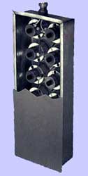
Fig.3 Submersible transducer
A general view of the ultrasonic submersible transducer with a partially cut out back cover is shown in Fig. 3. It can be seen that the piezoelectric emitters are arranged in several rows, two in each row.
Submersible ultrasonic transducers can be used both in ultrasonic cleaning baths specially designed for them, and in cleaning baths already available to the customer. The convenience of these converters is that they can be easily installed in various parts of the bath volume.
Unlike ultrasonic transducers, which are firmly attached to the cleaning bath at the bottom or side, submersible transducers can be replaced within minutes.
The generator for powering submersible transducers with high-frequency voltage can be located from the ultrasonic bath at a distance of up to 6 meters.
Methods for installing submersible transducers in an ultrasonic cleaning bath
Immersion transducers can be placed in cleaning baths in three different ways:
- placing the converter at the bottom of the bath;
- hanging on the wall of the bathtub;
- by mounting the converter on the wall of the bath.
Fig.4 Placement of the transducer in the ultrasonic bath
The first two methods do not require making holes in the wall of the bathtub.
Some types of mounting of a submersible transducer in an ultrasonic cleaning bath are shown in Fig. 4.
When placing the converter at the bottom of the bath, it is necessary to take into account the height of the layer of washing solution above the converter diaphragm.
You should strive to ensure that the height of this layer is a multiple of half the wavelength of ultrasonic vibrations transmitted into the washing solution by the submersible transducer.
In this case, due to the reflection of ultrasonic vibration waves from the water-air interface, a zone of standing waves is created in the cleaning solution (reverberation phenomenon). When ultrasonic waves reverberate in a liquid, the efficiency of ultrasonic cleaning is slightly higher.
As an example, we will determine the optimal height of this layer for a specific submersible transducer.
It is known that the speed of sound in water is 1485 m/sec. The wavelength of ultrasonic vibrations is equal to the speed of sound divided by the frequency of these vibrations.
Let's assume that we have a submersible ultrasonic emitter whose diaphragm oscillation frequency is 25,000 Hz (25 kHz). The wavelength in this case will be 0.0594 m. Half the wavelength is 0.0297 m or 2.97 cm. The optimal height of the liquid in this case above the surface of the submersible transducer should be 2.97 cm x n where n is any positive integer.

Fig.5 Standing waves in an ultrasonic bath
For example, for n=40, the optimal height of the level of the washing solution above the surface of the submersible converter will be 2.97x40=118.8 cm. The above is illustrated in Fig. 5.
Placing submersible ultrasonic transducers on the walls of the cleaning bath is recommended when its depth is more than half its width or length. In this case, the converters can be placed either on one wall of the bath or on its opposite walls.
The video shows the placement of submersible transducers on the side walls of the bath and the operation of submersible ultrasonic transducers located on the bottom of the bath.
Submersible transducers in action
Selecting the optimal frequency for a submersible converter
When ultrasonic vibrations propagate in a liquid, a phenomenon called cavitation occurs, which means the formation of cavitation cavities in the liquid in the rarefaction phase of the sound wave and its subsequent collapse in the compression phase.

Fig.6 Effect of frequency on ultrasound cavitation
The behavior of cavitation cavities when changing the oscillation frequency is shown in the graph in Fig. 6.
The y-axis on the left side shows the amount of energy released during the collapse of a single cavitation cavity (cavitation energy), and the y-axis on the right shows the number of cavitation cavities per unit volume of liquid.
As can be seen from the graph, with an increase in the frequency of ultrasonic vibrations, the number of cavitation cavities in the liquid increases, and the cavitation energy decreases.
As the frequency of ultrasonic vibrations decreases, the number of cavitation cavities in the liquid decreases, and the cavitation energy increases.
Moreover, for each frequency of ultrasonic vibrations, the product of the energy released by the cavitation cavity when it collapses by the number of these bubbles in the liquid is a constant value approximately equal to the energy transmitted into the liquid by the ultrasonic submersible transducer.
The influence of the frequency of ultrasonic vibrations on the number of cavitation cavities is discussed in detail on the website
For practice, it is important that the number of cavitation cavities be as large as possible, but at the same time the cavitation energy must be sufficient to remove contaminants. Thus, to clean parts from contaminants loosely bound to the surface (fats, oils), converters with a frequency of 35-40 kHz should be used, and to clean parts from contaminants firmly bound to the surface (polishing pastes, varnish and polymer films), submersible converters with a frequency of 35-40 kHz should be used. lower frequency 20-25 kHz.

change the picture
Fig. 7 Ultrasonic bath with converters of different frequencies
The most optimal solution is to create conditions when the number of cavitation cavities would be large and at the same time the cavitation energy would also be large.
These conditions are implemented in an ultrasonic cleaning bath with submersible transducers located on its walls, as shown in Fig. 7. Another option for the location of submersible transducers can be seen if you move the cursor to this figure.
In this case, two converters are used with different oscillation frequencies of 25 and 35 kHz. A converter with a frequency of 35 kHz ensures the creation of more cavitation cavities in the volume of washing liquid, and a converter with a frequency of 25 kHz increases the cavitation energy of these cavities.
Optimal number of immersion transducers for a cleaning bath
When determining the number of required submersible transducers, one must proceed from the fact that the maximum efficiency of ultrasonic cleaning is achieved with an ultrasonic power of 10...30 watts per 1 liter of bath volume.
For example, for a bathtub with a volume of 50 liters, two converters of the PP25.8 model are sufficient (see table below).
For large-volume ultrasonic cleaning baths, for example, over 250 liters, satisfactory results are achieved with an ultrasonic power of 4.5 watts per 1 liter of bath volume. For example, for a bath with a volume of 1000 l, 11 converters of the PP25.8 model are sufficient
Currently, there are many designs of ultrasonic submersible transducers on the domestic market.
The table shows the technical characteristics of submersible ultrasonic transducers from TNC Technosonic LLC (Moscow).
This article does not fully address all aspects of the design and use of submersible ultrasonic transducers. However, the presented material may be useful for specialists who are faced with specific tasks for the first time in choosing the optimal option for an ultrasonic bath for cleaning products.
Necessary for a very wide range of devices - repellers of mice, mosquitoes, dogs. Or simply as an ultrasonic washing machine. Also, with this EPU you can carry out interesting experiments and experiments (comrades add: including with neighbors :)). Can be used to reduce the time of etching and washing of printed circuit boards, reduce the time of soaking laundry. The acceleration of chemical processes in a liquid irradiated with ultrasound occurs due to the phenomenon of cavitation - the appearance in the liquid of many pulsating bubbles filled with steam, gas or a mixture of them and the sonocapillary effect. Below is a diagram of an ultrasonic variable frequency generator, taken from the Radioconstructor magazine.
The circuit is based on two rectangular pulse generators and a bridge power amplifier. A tunable ultrasonic frequency meander pulse generator is made on logic elements DD1.3, DD1.4. Its operating frequency depends on the capacitance of capacitor C3 and the total resistance of resistors R6, R4. The greater the resistance of these resistors, the lower the frequency. A low-frequency generator with an operating frequency of about 1 Hz is made using elements DD1.1, DD1.2. Both generators are connected to each other through resistors R3, R4. Capacitor C2 is designed to ensure that the frequency of the high-frequency generator changes smoothly. If capacitor C2 is bypassed with switch SA1, then the frequency of the high-frequency generator will be constant. A bridge pulse power amplifier is made using the DD2 chip and field-effect transistors.The inverters of the microcircuit drive push-pull repeaters on field-effect transistors. When at pins 3, 6 DD2 log. Oh, then there will be a log at the outputs DD2.3, DD2.4. 1. Accordingly, at this moment in time transistors VT1, VT4 will be open, and VT2, VT4 will be closed. Using a square wave signal results in harmonic-rich acoustic emissions. Two high-frequency dynamic heads of type 2GD-36-2500 are used as ultrasound emitters. You can also use 6GD-13 (6GDV-4-8), EGD-31 (5GDV-1-8) and other similar ones. If possible, it is advisable to replace them with a powerful piezoceramic emitter or magnetostrictor, which you can try to make yourself by winding several dozen turns of stranded copper wire on a ferrite U-shaped core from the TV fuel assembly, and using a small steel plate as a membrane. The coil must be placed on a massive support. P-channel field-effect transistors can be replaced with IRF5305, IRF9Z34S, IRF5210; p-channel - IRF511, IRF541, IRF520, IRFZ44N, IRFZ48N. Transistors are installed on radiators. The microcircuits can be replaced with 564LA7, CD4011A, K561LE5, KR1561LE5, CD4001B. Choke L1 - any miniature inductance 220.... 1000 µH. Resistors R7, R8 are homemade wire-wound ones. Variable resistor SP3-30, SP3-3-33-32 or with power switch SP2-33-20.Download the printed version in the archive.

Setup. The motor of the variable resistor R5 is set to the middle position, the contacts of the switch SA1 are closed, by selecting the capacitance of the capacitor C3 and the resistance of the resistor R6, the generator frequency is set to DD1.3, DD1.4 about 30 kHz. Next, contacts SA1 are opened and by selecting the resistances of resistors R2, R3 and R4, the ultrasonic frequency deviation should be set from 24 kHz to 35...45 kHz. It should not be made wider, since either the operation of the device will become audible to humans, or the switching losses of field-effect transistors will noticeably increase, and the efficiency of the sound emitters will decrease. Disruption of the generator on DD1.3, DD1.4 is not allowed, as this can lead to damage to the dynamic head coils. The power source must be designed for a current of at least 2 A. The supply voltage can be from 11 to 13 volts.

Today I assembled such a circuit for an ultrasonic emitter - it doesn’t work very well, but! Having thought a little, I came to the conclusion that it was necessary to increase the capacity of C3 to 2200 pF, then naturally the error in the circuit was eliminated - in the DD2.2 element, pins 4 and 6 were mixed up. And lo and behold, it works. True, it is not possible to withstand this piercing sound for a long time, varying over a wide range, even for those who are in other rooms. My head doesn’t even begin to hurt, but it’s as if it’s being squeezed in a vice, a sickeningly disgusting state, I lasted about 30 seconds.

The current consumption can be calculated based on the resistance of the ultrasonic emitter used; I think everyone remembers Ohm’s law. For example, I have it at 16 Ohms, taking the efficiency of 100% of the final stage as the efficiency, which is almost the case, we get 750 mA at a supply voltage of 12 V. The voltage should not be changed, otherwise the power will drop, and what’s the point of reducing it? I power my ultrasonic emitter from a 12 V power bank. When the voltage drops, the frequency is more or less stable. The range of output frequencies varies widely with a variable resistor from the audible spectrum to the inaudible, it is only necessary to select the correct duty cycle of the pulses for the correct operation of the circuit. The device was assembled and tested by: GOVERNOR.
UPGRADED ULTRASONIC GUN "IGLA-M"
Ultrasound - These are elastic waves of high frequency. Typically, the ultrasonic range is considered to be a frequency range from 20,000 to several billion hertz. Now ultrasound is widely used in various physical and technological methods. The fact that ultrasound actively affects biological objects (for example, kills bacteria) has been known for more than 70 years. Electronic equipment with a scanning ultrasound beam is used in neurosurgery to inactivate individual areas of the brain with a powerful, focused high-frequency beam. High-frequency vibrations cause internal heating of tissues.
There are still discussions about the physical effect of ultrasonic vibrations on the cell and even about the possible disruption of DNA structures. Moreover, there is information that at the micro level - not at the level of the body structure, but at some more subtle level - ultrasonic exposure is harmful.
Ultrasound can be obtained from mechanical, electromagnetic and thermal sources. Mechanical emitters are usually various types of intermittent sirens. They emit vibrations into the air with a power of up to several kilowatts at frequencies up to 40 kHz. Ultrasonic waves in liquids and solids are usually excited by electroacoustic, magnetostrictive and piezoelectric transducers.
The industry has long been producing devices forultrasonic effects on animals, for example:
Purpose
A miniature dog repeller is a wearable electronic device (assembled in a mini-flashlight housing) that emits ultrasonic vibrations that are audible to dogs and not perceptible to humans.
Operating principle
The device is designed to protect against dog attacks: ultrasonic radiation of a certain power usually stops an aggressive dog at a distance of 3 - 5 meters or puts it to flight. The greatest effect is achieved when acting on aggressive stray dogs.
Specifications
- Supply voltage (1 battery type 6F22 (KRONA)), V 9
- Current consumption, no more, A 0.15
- Weight with batteries, no more, g 90
As you understand, this is a weak toy, but we will make the device much more powerful! Continuing experiments with ultrasound (), a number of interesting improvements and improvements were made. This is how a revolutionary method of influencing a living organism (naturally negative) with two ultrasonicemitters with a difference frequency of several hertz. That is, the frequency of one emitter is, for example, 20,000 Hz, and the other is 20,010 Hz. As a result, onultrasonic radiation is superimposedsound, which greatly enhances the destructive effect!
The circuit is standard, a generator based on CD4069 + an amplifier with three N-P-N transistors. Power supply is at least 12 V, with a current of up to 1 A.

To enhance the directional effect, we use cylindrical sound resonators. Their role will be played by a regular nickel-plated tube from a vacuum cleaner.Just don’t spoil the vacuum cleaner; the tube is sold separately at the market or in a spare parts store.
We cut two pieces to an experimentally determined length (about a couple of centimeters), and attach them to HF heads like 5GDV-4 or any other. You can buy a double nozzle for the exhaust pipe of a car, installation is much more convenient, and the effect will be even better.

We insert the high-frequency speakers inside, and mount the board with the battery in the back.
When returning from work at night or wandering through dark alleys, there is a danger of being attacked by stray dogs, whose bites are sometimes life-threatening if you do not consult a doctor in time. It is for these cases that smart human brains came up with an ultrasonic repeller.
Industrial repellers have a rather complex design and are made with rather scarce components.
In this article we will look at a version of such a repeller using the famous 555 series timer. The timer, as you know, can work as a square pulse generator; this is exactly the connection used in the circuit.
The generator operates at a frequency of 20-22 kHz, as many animals are known to “communicate” in the ultrasonic range. Experiments have shown that frequencies of 20-25 kHz cause artificial fear in dogs; thanks to the tuning regulator, the generator can be adjusted to a frequency of 17-27 kHz.

The circuit itself contains only 6 components and will not cause any difficulties. It is advisable to use a multi-turn regulator for more precise tuning to the desired frequency.
The piezo emitter can be taken from a calculator or any other musical toys, you can also use any HF heads with a power of up to 5 watts, there is simply no point in doing more.
The device operates effectively at a distance of 3-5 meters, since there is no additional power amplifier in the circuit.

As a power source, it is convenient to use the crown, or any other source with a voltage of 6 to 12 volts.
List of radioelements
| Designation | Type | Denomination | Quantity | Note | Shop | My notepad |
|---|---|---|---|---|---|---|
| Programmable timer and oscillator | NE555 | 1 | To notepad | |||
| R1 | Resistor | 2.2 kOhm | 1 | To notepad | ||
| R2 | Resistor | 1 kOhm | 1 | To notepad | ||
| R3 | Variable resistor | 4.7 kOhm | 1 | To notepad | ||
| C1 | Electrolytic capacitor | 10 µF | 1 | To notepad | ||
| C2 | Capacitor | 10 nF | 1 | To notepad | ||
| Piezo emitter | 1 |
From short distances. Naturally, I immediately wanted to make a similar homemade product, since it is quite impressive and demonstrates in practice the work of electromagnetic pulses. The first models of the EMR emitter had several high-capacity capacitors from disposable cameras, but this design does not work very well due to the long “recharging” time. So I decided to take a Chinese high voltage module (commonly used in stun guns) and add a "punch" to it. This design suited me. But unfortunately, my high-voltage module burned out and therefore I could not film an article on this homemade product, but I had a detailed video on the assembly, so I decided to take some points from the video, I hope the Admin will not mind, since the homemade product is really very interesting.
I would like to say that all this was done as an experiment!
And so for the EMR emitter we need:
-high voltage module
-two 1.5 volt batteries
-box for batteries
-body, I use a 0.5 plastic bottle
-copper wire with a diameter of 0.5-1.5 mm
-button without lock
-wires
The tools we need are:
-soldering iron
-thermo glue
And so, the first thing you need to do is wind a thick wire of about 10-15 turns around the top of the bottle, turn to turn (the coil greatly affects the range of the electromagnetic pulse; a spiral coil with a diameter of 4.5 cm has shown to work best) then cut off the bottom of the bottle


We take our high-voltage module and solder the power supply through the button to the input wires, after first removing the batteries from the box


Take the tube from the handle and cut off a piece 2 cm long from it:


We insert one of the high-voltage output wires into a piece of tube and glue it as shown in the photo:

Using a soldering iron, we make a hole in the side of the bottle, slightly larger than the diameter of the thick wire:

We insert the longest wire through the hole inside the bottle:

Solder the remaining high-voltage wire to it:

We place the high-voltage module inside the bottle:

We make another hole on the side of the bottle, with a diameter slightly larger than the diameter of the tube from the handle:

We pull out a piece of tube with a wire through the hole and firmly glue it and insulate it with thermal glue:


Then we take the second wire from the coil and insert it inside a piece of tube, there should be an air gap between them, 1.5-2 cm, you need to select it experimentally


we put all the electronics inside the bottle, so that nothing shorts out, does not dangle and is well insulated, then glue it:


We make another hole along the diameter of the button and pull it out from the inside, then glue it:


We take the cut bottom and cut it along the edge so that it can fit onto the bottle, put it on and glue it:


OK it's all over Now! Our EMR emitter is ready, all that remains is to test it! To do this, we take an old calculator, remove valuable electronics and preferably put on rubber gloves, then press the button and bring the calculator up, electric current breakdowns will begin to occur in the tube, the coil will begin to emit an electromagnetic pulse and our calculator will first turn on itself, and then begin to randomly write numbers on its own !
Before this homemade product, I made an EMR based on a glove, but unfortunately I only shot a video of the tests; by the way, I went to an exhibition with this glove and took second place due to the fact that I showed the presentation poorly. The maximum range of the EMP glove was 20 cm. I hope this article was interesting to you, and be careful with high voltage!