UNIONAUSSR
REINFORCED CONCRETE FLOORS
MULTI-HOLLOW FOR BUILDINGS
AND STRUCTURES
TECHNICAL CONDITIONS
GOST 9561-91
Fromdofficial
STATE CO.MUSSR Institute of Civil Engineering
AND ININEATINGANDCANDYAM
GOSUDARWITHTINHENNYTH STANDARD OF THE USSR UNION
PE PLATESRREINFORCED CONCRETE COVERS
MULTI-HOLLOW FOR BUILDINGS AND
CONSTRUCTIONNIY GOST
TechnicalEUwhat conditions 9561- 91
Reinforced concrete multihollow panels
for floors in buildings. Specifications
___________________________________________________________
Date of introduction 01/01/92
This standard applies to reinforced concrete hollow-core slabs (hereinafter referred to as slabs), made from heavy, light and dense silicate concrete and intended for the load-bearing part of the floors of buildings and structures for various purposes.
The slabs are used in accordance with the instructions of the working drawings of the slabs and additional requirements specified when ordering these structures.
1. Technical requirements
1.1. The slabs should be manufactured in accordance with the requirements of this standard and technological documentation approved by the manufacturer, according to working drawings of standard structures (see Appendix 1) or designs of buildings (structures).
It is allowed, by agreement between the manufacturer and the consumer, to produce slabs that differ in types and sizes from those given in this standard, subject to the remaining requirements of this standard.
1.2. Main parameters and dimensions
1.2.1. Plates are divided into types:
1pc - 220 mm thick with round voids with a diameter of 159 mm. designed to be supported on two sides;
1PKT - the same, for support on three sides;
1PKK - the same, for support on four sides;
2PK - 220 mm thick with round voids with a diameter of 140 mm, designed for support on two sides;
2PKT - the same, for support on three sides;
2PKK - the same for support on four sides;
3PK - 220 mm thick with round voids with a diameter of 127 mm, designed for support on two sides;
3PKT - the same, for support on three sides;
3PKK - the same, for support on four sides;
4PK - 260 mm thick with round voids with a diameter of 159 mm and cutouts in the upper zone along the contour, intended for support on both sides;
5PK - 260 mm thick with round voids with a diameter of 180 mm, designed for support on two sides;
6PK - 300 mm thick with round voids with a diameter of 203 mm, designed for support on two sides;
7PK - 160 mm thick with round voids with a diameter of 114 mm, designed for support on two sides;
PG - 260 mm thick with pear-shaped voids, designed for support on two sides;
PB - 220 mm thick, manufactured by continuous molding on long stands and designed to be supported on two sides.
1.2.2. The shape and coordination length and width of the slabs (except for PB type slabs) must correspond to those given in table. 1 and to hell. 1-3. For buildings (structures) with a calculated seismicity of 7 points or more, it is allowed to manufacture slabs having a shape different from that indicated in the drawing. 1-3.
1.2.3. The structural length and width of the slabs (except for PB type slabs) should be taken equal to the corresponding coordination size (Table 1), reduced by A 1 (gap between adjacent slabs) or A 2 (distance between adjacent slabs if there is a separating element between them, for example, an anti-seismic belt, ventilation ducts, crossbar ribs), or increased by A 3 (for example, for slabs supported on the entire thickness of the walls of the staircase of buildings with transverse load-bearing walls). Values A 1 , A 2 and A 3 , are given in table. 2.
1.24. The shape and dimensions of PB type slabs must correspond to those established in the working drawings of the slabs, developed in accordance with the parameters of the molding equipment of the manufacturer of these slabs.
Table 1
|
Drawing number |
Coordination dimensions of the slab, mm |
||
|
slabs |
slabs |
Length |
Width |
|
From 2400 to 6600 inclusive. at intervals of 300, 7200, 7500 |
1000, 1200, 1500, 1800, 2400, 3000, 3600 |
||
|
1000, 1200, 1500 |
|||
|
From 3600 to 6600 inclusive. at intervals of 300, 7200, 7500 | |||
|
From 2400 to 3600 inclusive. at intervals of 300 |
From 4800 to 6600 inclusive. at intervals of 300, 7200 |
||
|
From 2400 to 6600 inclusive. at intervals of 300, 7200, 9000 |
1000, 1200, 1500 |
||
|
6000, 9000, 12000 |
1000, 1200, 1500 |
||
|
1000, 1200, 1500 |
|||
|
From 3600 to 6300 inclusive. at intervals of 3000 |
1000, 1200, 1500, 1800 |
||
|
6000, 9000, 12000 |
1000, 1200, 1500 |
||
Notenie. The length of the slabs is taken to be:
the size of the side of the slab not supported by the load-bearing structures of the building (structure) - for slabs intended to be supported on two or three sides;
the smaller size of the slab in plan - for slabs intended to be supported along the contour.
Plates types 1PK, 2PK, 3PK, 5PK, 6PK, 7PK

Plates types 1PKT, 2PKT, 3PKT

Plates of types 1PKK, 2PKK, 3PKK


Plate type 4pcs


Plate type PG


Notes to hell 1-3
1. Slabs of types 1PKT, 2PKT, 3PKT, 1PKK, 2PKK and 3PKK can have technological bevels along all side faces.
2. Methods for strengthening the ends of the slabs are shown in Figures 1-3 as an example. It is permissible to use other methods of reinforcement, including reducing the diameter of the voids through one on both supports without sealing the opposite ends of the voids.
3. The dimensions and shape of the groove along the longitudinal upper edge of slabs of types 1PKT, 2PKT and 3PKT (Drawing 1b) and along the contour of slabs of type 4PK (Drawing 2) are established in the working drawings of the slabs.
4. In slabs intended for buildings (structures) with a calculated seismicity of 7-9 points, extreme voids may be absent due to the need to install embedded products or produce reinforcement for connections between slabs, walls, and anti-seismic belts.
table 2
|
Scope of application of plates |
Additional dimensions taken into account when determining design size slabs, mm |
|||
|
length |
widthA 1 |
|||
|
A 1 |
A 2 |
A 3 | ||
|
Large-panel buildings, including buildings with a calculated seismicity of 7-9 points Buildings (structures) with walls made of bricks, stones and blocks, with the exception of buildings (structures) with a calculated seismicity of 7-9 points Buildings (structures) with walls made of bricks, stones and blocks with a calculated seismicity of 7-9 points Frame buildings (structures), including buildings (structures) with a calculated seismicity of 7-9 points |
10 - for slabs with a coordination width of less than 2400. 20 - for slabs with a coordination width of 2400 or more |
|||
1.2.5. Voids in slabs intended to be supported on two or three sides should be located parallel to the direction along which the length of the slabs is determined. In slabs intended to be supported on four sides, the voids should be located parallel to any side of the slab contour.
The nominal distance between the centers of voids in slabs (with the exception of slabs of types PG and PB) should be taken as no less than, mm:
185 - in slabs of types 1PK, 1PKT, 1PKK, 2PK, 2PKT, 2PKK, 3PK, 3PKT, 3PKK and 4PK;
235 - in slabs of type 5PK;
233 " " " 6pcs;
139 « « « 7pcs.
The distance between the centers of the voids of slabs of types PG and PB is determined in accordance with the parameters of the molding equipment of the manufacturer of these slabs.
1.2.6. The slabs should be made with recesses or grooves on the side edges to form, after embedding, intermittent or continuous keys that ensure the joint operation of the floor slabs for shear in the horizontal and vertical directions.
By agreement between the manufacturer and the consumer and the design organization - the author of the project for a specific building (structure), it is allowed to produce slabs without recesses or grooves for the formation of keys.
1.2.7. Slabs intended to be supported on two or three sides should be made prestressed. Slabs with a thickness of 220 mm, a length of less than 4780 mm, with voids with diameters of 159 and 140 mm and slabs with a thickness of 260 mm, with a length of less than 5680 mm, as well as slabs with a thickness of 220 mm, of any length, with voids with a diameter of 127 mm may be manufactured with non-prestressing reinforcement.
1.2.8. The slabs should be made with reinforced ends. Strengthening the ends is achieved by reducing cross section voids on supports or filling voids with concrete or concrete liners (Fig. 1-3). When the design load on the ends of the slabs in the wall support zone does not exceed 1.67 MPa (17 kgf/cm2), it is allowed, by agreement between the manufacturer and the consumer, to supply slabs with unreinforced ends.
Methods of strengthening and minimum dimensions seals are established in working drawings or indicated when ordering slabs.
1.2.9. In cases provided for by the working drawings of a particular building (structure), slabs may have embedded products, reinforcement outlets, local cutouts, holes and other additional structural details.
1.2.10. To lift and install slabs, mounting loops or special gripping devices are used, the design of which is established by the manufacturer in agreement with the consumer and the design organization - the author of the building (structure) project. The location and dimensions of holes in slabs intended for loopless installation are taken according to the drawings included in the package. project documentation gripping device for these slabs.
1.2.11. The consumption of concrete and steel on slabs must correspond to those indicated in the working drawings of these slabs, taking into account possible clarifications made design organization according to established order.
1.2.12. The slabs are used taking into account their fire resistance limit specified in the working drawings of the slabs.
1.2.13. The slabs are designated by marks in accordance with the requirements of GOST 23009. The slab mark consists of alphanumeric groups separated by hyphens.
In the first group, indicate the designation of the type of slab, the length and width of the slab in decimeters, the values of which are rounded to the nearest whole number.
In the second group indicate:
design load on the slab in kilopascals (kilogram-force per square meter) or the serial number of the slab by load-bearing capacity;
steel class of prestressed reinforcement (for prestressed slabs);
type of concrete ( L - lightweight concrete, C - dense silicate concrete; heavy concrete is not indicated).
In the third group, if necessary, additional characteristics are indicated that reflect the special conditions of use of the slabs (for example, their resistance to aggressive gaseous media, seismic influences), as well as designations of the design features of the slabs (for example, the presence of additional embedded products).
EtcAndconditional measures indicatedAndI(grade) slab type 1PK with a length of 6280 mm, a width of 1490 mm, designed for a design load of 6 kPa, made of lightweight concrete with prestressed reinforcement of class At-V.
3* rub BZ s-#1/911
STATE STANDARD
USSR UNION
REINFORCED CONCRETE MULTI-HOLLOW FLOORS PLATES FOR BUILDINGS AND STRUCTURES
TECHNICAL CONDITIONS
GOST 9561-91
Official publication
USSR STATE COMMITTEE FOR CONSTRUCTION
AND INVESTMENTS
UDC 691.328:006.354 ZhZZ Group
STATE STANDARD OF THE USSR UNION
REINFORCED CONCRETE MULTI-HOLLOW FLOORS PLATES FOR BUILDINGS AND STRUCTURES
Reinforced concrete multihollow panels for floors in buildings. Specifications
Date of introduction 01/01/92
This standard applies to reinforced concrete hollow-core slabs (hereinafter referred to as slabs), made from heavy, light and dense silicate concrete and intended for the load-bearing part of the floors of buildings and structures for various purposes.
The slabs are used in accordance with the instructions of the working drawings of the slabs and additional requirements specified when ordering these structures.
1. TECHNICAL REQUIREMENTS
1.1. Plates should be manufactured in accordance with the requirements of this standard and technological documentation approved by the manufacturer, according to working drawings standard designs(see Appendix 1) or designs of buildings (structures).
It is allowed, by agreement between the manufacturer and the consumer, to produce slabs that differ in types and sizes from those given in this standard, subject to the remaining requirements of this standard.
1.2. Main parameters and dimensions
1.2.1. Plates are divided into types:
1G1K - 220 mm thick with round voids with a diameter of 159 mm, intended for support on two sides;
1PKT - the same, for support on three sides;
1PKK - the same, for support on four sides;
Official publication
<6) Издательство стандартов, 1992
This standard cannot be reproduced in whole or in part”, replicated and distributed without permission from the USSR State Construction Committee
2PK - 220 mm thick with round voids with a diameter of 140 mm, designed for support on two sides;
2PKT - the same, for support on three sides;
2PKK - the same, for support on four sides;
ZPK - 220 mm thick with round voids with a diameter of 127 mm, designed for support on two sides;
ZPKT - the same, for support on three sides;
ZPKK - the same, for support on four sides;
4PK - 260 mm thick with round voids with a diameter of 159 mm and cutouts in the upper zone along the contour, intended for support on both sides;
5PK - 260 mm thick with round voids with a diameter of 180 mm, intended for support on two sides;
6PK - 300 mm thick with round voids with a diameter of 203 mm, designed for support on two sides;
7PK - 160 mm thick with round voids with a diameter of 114 mm, designed for support on two sides;
PG - 260 mm thick with pear-shaped voids, designed for support on two sides;
PB - 220 mm thick, manufactured by continuous molding on long stands and designed to support the cue on two sides.
1.2.2. The shape and coordination length and width of the slabs (except for PB type slabs) must correspond to those given in table. 1 and to hell. 1-3. For buildings (structures) with a calculated seismicity of 7 points or more, it is allowed to manufacture slabs having a shape different from that indicated in the drawing. 1-3.
1.2.3. The structural length and width of the slabs (except for PB type slabs) should be taken equal to the corresponding coordination size (Table 1), reduced by the value a\ (the gap between adjacent slabs) or ao (the distance between adjacent slabs if there is a separating element between them, for example , antiseismic belt, ventilation ducts, crossbar ribs), or increased by a value of 3 (for example, for slabs supported on the entire thickness of the walls staircase buildings with transverse load-bearing steps). The values of a b i 2 and a 3 are given in table. 2.
1.2.4. The shape and dimensions of PB type slabs must correspond to those established in the working drawings of the slabs, developed* in accordance with the parameters of the molding equipment of the manufacturer of these slabs.
Table I
|
Coordmmatsvomvma sizes of jasper. mi |
|||
|
From 2400 to 0600 “key, with it* tgraalim 300. 7200, 7500 |
1000. 1200. 1500. |»Yu. 24001 JC.X). 3600 |
||
|
1000. 1200. 1509 |
|||
|
From 3600 to 6600 ahlyuch. with no price 300. 7200. 7500 |
From 2400 to 3600 rolls.< и»* тсрвалом 300 |
||
|
(PC to APKK |
From 2400 to 3600 ashp. with mm* irpiaiou 300 |
From 4800 to 6609 key? ii~ a fault 300 7200 |
|
|
From 244)0 to 6600 nkey. with km* >srva~chom 300. 7200. 9000 |
1000. 1200. 1500 |
||
|
LOOOO; 9000; 12000 |
1000, 1200. 1500 |
||
|
1000, 1200. 1500 |
|||
|
From 3600 to 6300 microkeys. at intervals of 300 |
i000. 1200. 1500,\Ш |
||
|
6000, 9000. 12000 |
100i. 1200. 1500 |
||
Note For the lengths of the slabs:
the size of the side is poured in, and* resting on the issushi* “ois/uukdmya alshma (structure) - for pdnt, and red bottom z on the possible long oanraaik io da > y *im three< ; м>-rona;
throwing from the dimensions of the vlit “shsh-y* poured, dda mv”*
in the outline
Ptittshtv Yun. 7PK.ZPK. 5LKMSSH

Understood types YUNG, 2PK7, ZLIT


Poit types MNI,
gpkp.zpkk

Plate type 4pcs


Plsha went PG

With swords" to hell. 1-3
I. Some types 1PKT, 2PKT, ZG1KT, 1PKK, 2PKK and ZPKK may have bevels along the side edges.
2 Sp^pLi strengthening of the tori plates are shown on the devil. I-3 I quality at* pearl. .ItmvcKacfCR the use of other methods of telemetry, including reducing the diameter of the voids through writing on both supports without deposits of the opposite * nnd computer puetog.
3. The shape of the groove along the longitudinal upper edge of slabs of types 1PKT, 2PKT n ZPKT (Drawing 16) and along the contour of slabs of type 4PK (Drawing 2) are indicated* in the working drawings of the slabs.
4. II slabs intended for buildings (structures) with a calculated seismicity of 7-9 points, the outermost voids may not be stomped in the space with the need to install embedded products kin releases of reinforcement for connections between the slabs and walls. antiseismic belts.
table 2
|
Additional* dimensions taken into account when determining the structural size of the slab, mm |
||||
|
Obmet arichemvm Mitt | ||||
|
Large-panel buildings. and yum members of the building with a calculated seismicity of 7-9 points |
10 - for slabs with a coordination width of less than 2400. 20 -* for slabs |
|||
|
Lgainya (structures) with walls made of bricks, stones and blocks, with the exception of buildings (co-or> zheiny) with an estimated seismic rating of 7-H points |
coordination width 2400 or more |
|||
|
Buildings (structures) with walls made of bricks, stones and blocks with a calculated seismicity of 7- -9 points | ||||
|
K s r * a s i s evil (structure-HMiH, including buildings (structure) with a calculated seismicity of 7-9 points | ||||
12.5. The voids in the slabs intended to be supported along one or three sides should be placed parallel to the group on which the length of the slabs is determined. In slabs intended to be supported on four sides, the voids should be located parallel to any side of the slab contour.
The nominal distance between the centers of voids in slabs (with the exception of slabs of types PG and PB) should be taken at least, mm
165- and slabs type 1 pc. 1PKT. 1PKK. 2PK, 2PKT, 2PKK. ZPK. ZPKT. ZPKK and 4PK:
£3.$- » plates type 5PK;
23,"" * * * 6pcs;
139 » * * Civil Procedure Code.
The distance between the centers of the voids of slabs of types G1G and G1G> ml is determined in accordance with the parameters of the molding equipment of the manufacturer of these slabs.
1.2.6. The slabs should be made with recesses or grooves on the side faces to form, after installation, intermittent or continuous keys that provide working together floor slabs for shear in the horizontal and vertical directions.
By agreement between the manufacturer and the consumer and the design organization - the author of the project for a specific building (structure), it is allowed to produce slabs without recesses or grooves for the formation of keys.
1.2.7. Slabs intended to be supported on two or three sides should be made prestressed. Slabs with a thickness of 220 mm, a length of less than 4780 mm, with hollows with diameters of 159 and 140 mm and slabs with a thickness of 260 mm, a length of less than 5680 mm, as well as slabs with a thickness of 220 mm , of any length, with voids with a diameter of 127 mm, can be manufactured with non-stressed reinforcement.
1.2.8. The slabs should be topped with reinforced ends. Strengthening of the butts reached;*.,; reducing the cross-section of voids on supports or filling voids with concrete or concrete liners (Fig. 1 - 3). When the design load on the ends of the slab in the zone of support of the walls does not exceed 1.67 MPa (17 kg/cm*), it is allowed, by agreement between the manufacturer and the consumer, to supply slabs with unreinforced ends.
Methods of reinforcement and minimum dimensions of embedments are specified in the regulations in the working drawings or indicated by law.
1.2.9. In cases provided for by the working drawing of a particular building (structure), slabs may have embedded products, reinforcement outlets, local cutouts, holes and other additional structural details.
1.2.10. For lifting and installation of slabs, clamping hinges or special gripping devices are used, the design of which is established by the manufacturer in consultation with the consumer and the design organization - the author of the project was angry and I (I will erase the fabric). The location and dimensions of the holes in the slab*, precondition "about? turnips for pinless installation, accept according to drawings included in the design documentation of gripping devices* for these slabs.
1.2.11. Indicators of concrete and steel consumption for dremtad slabs
correspond to those specified in the working drawings -** subsided al and g, taking into account possible clarifications made by nr<>ekgyoy guns"
in the hectares eaten in the order.
1 ? 12 The slabs are used taking into account - nr-ed.,* >l Dt -:m: t and, rolled in the working drawings of the slabs.
1.2.13. The slabs are designated by marks in accordance with the requirements of GOST 23009. The slab mark consists of alphanumeric groups separated by hyphens.
In the first group, indicate the designation of the type of slab, the length and width of the slab in decimeters, the value of which is rounded to the nearest whole number.
In the second group indicate:
design load on the slab in kilopscals (kilogram-force per square meter) or serial number slabs according to load-bearing capacity;
steel class of prestressed reinforcement (for prestressed slabs);
type of concrete (L - lightweight concrete, C - dense silicate concrete; heavy concrete is not indicated).
In the third group, if necessary, indicate additional characteristics, reflecting special conditions application of slabs (for example, their resistance to aggressive gaseous media, seismic influences), as well as designations design features slabs (for example, the presence of additional embedded products).
Example symbol(grade) slab type 1PK with a length of 6280 mm, a width of 1490 mm, designed for a design load of 6 kPa, made of lightweight concrete with prestressed reinforcement of class At-V:
t P K63J5-6AtVJ1
Same. made of heavy concrete and intended for use in buildings with a calculated seismicity of 7 points:
1PK63.15-6AtU-S7
P g to 1 m a i m e It is allowed to accept the designation of brands of Plates in accordance with
^'«■TCTtui I . working drawings of the slabs before their revision.
13 Characteristics
13 1. The slabs must meet the requirements established during the design for strength, rigidity, crack resistance and their loading in cases specified in the drawings, and withstand control loads.
1.3 "£ Plates must meet the requirements of GOST 13015.0:
to indicators of the actual strength of concrete (at design age, transfer and tempering);
in terms of frost resistance of concrete, and for slabs operated under exposure to an aggressive gaseous environment - also in terms of waterproof HA of concrete;
Fri. with massacre density of lightweight concrete:
b steel grades for reinforcement and embedded products, including
mounting loop chip;
by deviations in the thickness of the protective layer of concrete up to the yoke;
for corrosion protection.
Slabs used as the load-bearing part of loggias must also meet the additional requirements of GOST 25697.
1.3.3. Slabs should be made of heavy concrete in accordance with GOST 26633, structural lightweight concrete of a dense structure with an average density of at least 1 * 100 kg/m 1 in accordance with GOST 25820 or dense silicate concrete with an average density of at least 1600 kg/m* but GOST 25214 strength classes or grades for compression specified in the working drawings of these slabs.
1.3.4. The compression forces (releasing the tension of the reinforcement) are transferred to the beta after it reaches the required transfer strength.
The normalized transfer strength of concrete of prestressed slabs, depending on the class or grade of concrete in terms of compressive strength, the type and class of prestressing reinforcing steel, must correspond to that indicated in the working drawings of these slabs.
1.3.5. The normalized tempering strength of concrete of pre-stressed slabs made of heavy or light concrete for the warm period of the year should be equal to the normalized pre-temperature strength of concrete, and slabs with non-stressed reinforcement - 70% of the compressive strength of concrete corresponding to its class or grade. When delivering these slabs » cold season or for<»беспечення сохранности их при перевозке железнодорожным транспортом в теплый период года (по согласованию м»жду изготовителем и потребителем плит) нормируемая отпуск! оя прочность бетона может быть повышена до 85% прочности бетона ид сжатие, соответствующей его классу или марке.
The normalized tempering strength of concrete slabs made of dense silicate concrete should be equal to 100% of the concrete compressive strength corresponding to its class or grade.
1.3.6. For reinforcing slabs, reinforcing steel of the following grades should be used:
as prestressed reinforcement - thermo-mechanically strengthened rod of classes At-IV, Ar-V and At-VI according to GOST 10881 (regardless of weldability and increased resistance to corrosion cracking of the reinforcement), hot-rolled rod of classes A-IV, A-V and A-Vl according to GOST 57N!, aryktuchkie kuh.wm class■ vз К 7 according to GOST 138-10. vyschkopro tuyu "eye g.erzo.sh-
Cheskogn profile class Br-N according to I (I T 73;Y, pr^gn l< & . сд
ilp-OOO according to TU I-4-GZ"-"2 n perzhneayu dryaguru k.ta<>-a L Shi,
made of non-preferred steel class A-Ill according to GOST 5781, strengthened by drawing with control of the stress value to the ultimate elongation:
as prestressing reinforcement - hot-rolled rods of periodic profile of classes A-ll. A*Sh and smooth class A-1 according to GOST 5781, periodic wire of class VR-1 according to GOST 6727 and class VR SOO according to TU 14-4-1322.
In slabs produced by the methods of continuous formless molding on long stands, continuous reinforcement, as well as using multi-temperature electrothermal tension, high-strength wire reinforcement is used in accordance with GOST 7348 and ropes in accordance with GOST 13840.
1.3.7. The shape and dimensions of reinforcement and embedded products and their position in the slabs must correspond to those indicated in the working drawings of these slabs.
1.3.8. Welded reinforcement and embedded products must comply with the requirements of GOST 10922.
1.3.9. The stress values in the prestressing reinforcement, monitored after tensioning it on the stops, must correspond to those indicated in the working drawings of the slabs.
The values of actual stress deviations in prestressed reinforcement should not exceed the limits specified in the working drawings of the slabs.
1.3.10. The values of the actual geometric deviations and parameters of the slabs must exceed the limits specified in the table. 3.
Table 3
Continuation of the table. 3
* Deviation from the size that determines the position. outside the embedded part, the upper plane of the slabs intended for a linoleum sticker should only be inside the slab.
1.3.11. Requirements for the quality of concrete surfaces appearance slabs (including requirements for the permissible opening width of technological cracks) - according to GOST 13015.0 and this standard.
1.3.12. The quality of concrete slab surfaces must meet the requirements established for the category!
AZ - lower (ceiling);
A7 - top and side.
By agreement between the manufacturer and the consumer, the following categories of surfaces can be installed instead of the indicated ones:
A2 - lower (ceiling), prepared for painting;
A4 - the same, prepared for wallpapering or decorative finishing paste-like compositions, and the top, prepared for covering with linoleum;
A6 - lower (ceiling), for which there are no requirements for the quality of finishing.
1.3.13. In concrete slabs supplied to the consumer, cracks are not allowed, with the exception of shrinkage and other surface, technological cracks with a width of no more than 0.3 mm on the top surface of the slabs and no more than 0.2 mm on the side and bottom surfaces of the slabs.
1.3.14. Exposure of reinforcement is not allowed, with the exception of reinforcement outlets or ends of prestressing reinforcement, which should not protrude beyond the end surfaces of the slabs by more than 10 mm and should be protected with oil cement-sand mortar or bitumen varnish.
1.4. Marking
Marking of slabs is in accordance with GOST 13015.2. Markings and signs should be applied to the side faces or top surface of the slab.
The upper surface of the slab, supported on three sides, should be marked with “Location of support” signs in accordance with GOST 13015.2, located in the middle on each side of the support structure.
2. PRIEEL1KA
2.1. Acceptance of slabs - in accordance with GOST 13015 1 and this standard. G1rp this slabs are accepted according to the results:
periodic testing - in terms of strength, rigidity and crack resistance of slabs, frost resistance of concrete, porosity (volume of intergranular voids) of a compacted mixture of lightweight concrete, as well as water resistance of concrete slabs intended for use in conditions of exposure to an aggressive environment;
acceptance tests - in terms of concrete strength (class or grade of concrete in terms of compressive strength, transfer and tempering strengths), average density of light or dense silicate concrete, compliance of reinforcement and embedded products with working drawings, strength of welded joints, accuracy geometric parameters, the thickness of the protective layer of concrete to the reinforcement, the width of the opening of technological cracks and the category of the concrete surface.
2.2. Periodic testing of slabs by loading to control their strength, rigidity and crack resistance is carried out before the start of their mass production and subsequently when making changes to them and when changing the temperature of production, as well as in the process of mass production slabs at least once a year. Load testing of slabs in the event of structural changes being made to them and when manufacturing technology is changed, depending on the essence of these changes, should not be carried out in agreement with the design organization - the developer of the working drawings of the slabs.
Testing of slabs with a length of 5980 mm or less during their serial production should not be carried out if non-destructive testing is carried out in accordance with the requirements of PC* G J30I5 1.
2.3. Slabs in terms of the accuracy of geometric parameters, the thickness of the protective layer of concrete before the reinforcement, the width of the opening of technological cracks and the category of the concrete surface should be accepted based on the results of random inspection.
2.4. The capacity (volume of intergranular voids) of a compacted mixture of lightweight concrete should be determined at least once a month.
2.5. The document on the quality of slabs intended for use in conditions of exposure to aggressive environments must additionally indicate the grade of concrete for water resistance (if this indicator is specified in the order for the production of slabs).
3. CONTROL METHODS
3.1. Load tests of slabs to control their strength, rigidity and crack resistance should be carried out in accordance with the requirements of GOST 8829 and working drawings of these slabs.
3.2. The strength of concrete slabs should be determined according to GOST 10380 pas for samples made from concrete mixture working personnel and stored in conditions established by GOST 18105.
When determining the strength of concrete using non-destructive testing methods, the actual transfer and impact compressive strength of concrete is determined by the ultrasonic method according to GOST 17624 or by instruments mechanical action according to GOST 22690. It is allowed to use other non-destructive testing methods provided for by the standards for concrete testing methods.
3.3. The frost resistance of concrete slabs should be determined according to GOST 10060 or by the ultrasonic method according to GOST 26134 on a series of samples made from a concrete mixture of the working composition.
3.4. The water resistance of concrete slabs intended for installation in conditions of exposure to an aggressive environment should be determined according to GOST 12730.0 and GOST 12730.5.
3.5. Average density light and dense silicate concrete should be determined according to GOST 12730.0 and GOST G2730.1 or by the radioisotope method according to GOST 17623.
3.6. The porosity indicators of a compacted mixture of lightweight concrete should be determined!” but GOST 10181.0 and GOST 10181.3.
3.7. Inspection of welded reinforcement and embedded products - in accordance with GOST 10922 and GOST 23858.
3.8. The tension force of the reinforcement, controlled at the end of the tension, is measured according to GOST 22362.
3.9. The dimensions of the slabs, deviations from the straightness and flatness of the surfaces of the slabs, the width of the opening of technological grooves, the sizes of shells, sagging and edges of concrete slabs should be determined by the methods established by GOST 26433.0 and GOST 36433.1.
3.10. The dimensions and position of reinforcement and embedded products, as well as the thickness of the protective layer of concrete up to the reinforcement, should be determined according to GOST 17625 and GOST 22904. In the absence of the necessary equipment, cutting furrows and exposing the slab reinforcement with subsequent sealing of the furrows is allowed. Furrows should be punched at a distance from the ends not exceeding 0.25 lengths* of the slab.
4. TRANSPORTATION AND STORAGE
4.1. Transportation and storage of slabs - in accordance with GOST 13015.4 and this standard.
4.2. The slabs should be transported and stored in stacks laid in a horizontal position.
On specialized vehicles it is allowed to transport slabs in an inclined or vertical position.
4.3. The height of the stack of slabs should not be more than 2.5 m.
4.4. Pads for the bottom row of slabs and spacers between them in a stack should be located near the mounting loops.
LIST OF SIZES AND SERIES OF WORKING DRAWINGS OF PLATES FOR MASSIVE APPLICATION
Table 4
|
TyPOraEMIR |
Designation of series 1 Standard size of working drawings! slabs and slabs | ||
|
1.141-1; 1.141.1-ZES |
|||
|
1tK59.15 1PK59.12 1 PK59.10 |
1.141-18s; 1.141 1-25s; 1.141.1-32s |
||
|
1.241-1; 1.090.1-I; 1 1.090.1- 2s; 1.090.1-Salary in; |
|||
|
11 PK56.30 1PK56.15 1PK56.12 1PK56.9 | |||
|
1.141-18s; 1.141.1-25s; 1 1.141.1-L2s |
|||
|
1.141-1; 1.141.1-33s |
|||
|
1.241-1; 1.090.1-1 |
|||
|
1 141-1; 1.141.1-33s |
|||
|
1.‘41- 1; 1.141.1- 33s; 1.141.1-30 |
|||
|
11G1K51.12 1PK51.Yu |
1.1 1-1; 1.141.1- 33s |
||
|
1.141-1; 1.141.1- 33s I |
|||
|
1.141-1; 1.141.1-EZe |
|||
|
1.141-1; 1.141.1-VO; 1 1.141.1-33s |
|||
|
1.141.1; 1.141.1-33с; 1.141.1-30 |
|||
|
1.141-1; 1.141.1-33с ] |
|||
|
1PK48.12 t K 48.10 |
1.141-1; 1.141.1-33s |
||
|
1PK62.15 1PK62 12 1PK62.10 | |||
|
1.141-18s; 1.141.1-25s; 1.141.1-32s |
|||
|
1.141-1; 1.141.1-33s |
|||
|
1L41-1; 1.NY-OEs; 1.090.1- 2s; 1.090.1-Zpa; |
|||
Continuation of the table. 4
1PK36L8 1PK36L5 1PK26 12 1PK36L0
1PK30 15 1PK30L2
1PK29L8 1PK29L5 1PK29 12 1PK29L0
IPK27L5 1G1K27 12 1PK27.9
1ьУ23 !8 1PK2L *5
I PC 23! 2 11IV 23 12
shk?3 M)
2PK60 36 2PK60.35 2PK60.30 2PK60.26 2G1K60.24 2PK60L8 2PK60L2
1.141-1; 1,090L - 1; 1.090L-2s; 1.090L-Zpv; 1.090L-5s
2PK30.66 2PK30.60 211 KZ 0.54 2 L KZ 0.4 8 2PK30L8 2PK30L2
ZG1KZO.ZO
1L41L-28s; 1L41L-29s
4PK72L 5 4PK72L2
1.141 - i; 1.090.1-1; 1.090.1-2s; 1.090 1-Zpv, 1.090 I-5s
* iNVrtJvi И>
\ N1.1 M41L~29sI)Kai5
411K For/ 5 2 I
OOozmch "M1YU Germa working drawings AMT
141; E-600; 3-600IV; E600N TSIIEEP dwellings
135 KB on reinforced concrete named after. A. A. Yakusheva
86-3191/1 TSIIEP of commercial and household buildings and tourist complexes"
86-3191/1 TSIIEP of commercial and household buildings and tourist complexes
86-3191/1 TSIIEP commercial buildings and tourist complexes^ _______ _ _
Continuation of the table. *7
|
Tyaporaamer |
Designation of series of working drawings of beaches |
Tyaporaamer |
Designation of a series of working drawings of slabs |
|
86-3191/1 TsNIIEP | |||
|
commercial buildings and tourist complexes |
7PK51.18 7PK51.12 | ||
|
5PK 116.15 5PK116.12 | |||
|
PP 16.15 PG116.12 G1GP6.9 | |||
|
5PK56 12 5PKY1.9 |
28-87 TsNIIproyzda-nny |
||
AREA OF APPLICATION OF VARIOUS TYPES OF PLATES
Table 5
|
Reduced slab thickness, and |
DENSITY |
Characteristics of adayan (construction) |
||
|
Up to 7.2 shslyuch. |
Residential buildings. about which the required* 1choiz*elite.1I of residential premises is provided by the installation of hollow-core, floating, non-hollow-core layered floors, as well as single-layer strips on a leveling screed |
|||
|
Up to 9.0 incl. |
About the company other non-waterproof buildings (structures) |
|||
|
2PK 2i IKT 2G1KK |
Up to 7.2 keys |
Residential buildings in which the required sound insulation of residential premises is ensured by building single-layer FLOORS |
||
|
Up to 6.3 incl. |
Residential large-panel buildings Sern N 135, in which the required sound insulation of premises is emphasized by the installation of SINGLE-LAYER FLOORS |
|||
|
Up to 9.0 incl. |
Public and industrial buildings (structures) |
|||
|
Residential knowledge unimportant m ugchdgbneno tina |
APPENDIX 3 Information
TERMS USED IN APPENDIX 2 AND THEIR EXPLANATIONS
Table &
|
Explanation |
|
|
Single layer floor |
A floor consisting of a covering (linoleum on a heat- and sound-insulating basis) laid directly on the floor slabs or on a leveling screed |
|
Single-layer floor on a leveling screed |
A floor consisting of a covering (linoleum on a thermal and soundproofing basis), laid with a leveling screed |
|
Hollow floor |
A floor consisting of a hard covering along joists and soundproofing pads laid on floor slabs |
|
Voidless layered floor |
A floor consisting of a hard surface AND a THIN soundproofing layer, laid directly on the floor slabs or on a leveling screed |
|
Floating floor |
A floor consisting of a covering, a rigid base in the form of a monolithic or prefabricated screed and a continuous soundproofing layer of elastic-soft silt bulk materials laid on floor slabs |
INFORMATION DATA
I. DEVELOPED AND INTRODUCED by the State Committee for Architecture and Urban Planning under the USSR Gosstroy (Gos-Comarchitecture) and the Central Research and Design Experimental Institute industrial buildings and structures (TsNIIpromzdany) of the USSR State Construction Committee
DEVELOPERS
L. S. Exler; A. A. Muzyko (topic leaders); I. I. Pod-guzova; A, A. Tuchiin, Ph.D. tech. sciences; E. N. Kodysh, Ph.D. tech. sciences; I. B. Baranova; V. G. Kramar, Ph.D. tech. sciences; G. I. Berdichevsky, Doctor of Engineering. sciences; V. L. Morozensky, Ph.D. tech. sciences; Yu. Ts. Khodosh; B. V- Karabanov, Ph.D. tech. Sciences: V.V. Sedov; E. L. Shakhova; B. N. Petrov; Ya 3. Gilman; G. V. Turmanidze; N. A. Kapanadze; B, V. Kroshkov; V. I. Pimenova; V. I. Denshchikov
G2. APPROVED AND ENTERED INTO EFFECT by Resolution of the USSR State Committee for Construction and Investment dated September 20, 1991 No. 5
3. INSTEAD OF GOST 9561-76 and GOST 26434-85 regarding types, main dimensions and parameters of hollow-core slabs
4. REFERENCE REGULATIVE AND TECHNICAL DOCUMENTS
|
GOST 5781-82 |
GOST 17023-87 | ||
|
GOST 6727-80 |
GOST 17624-87 | ||
|
GOST 7348-81 |
G"OSG 17625-83 | ||
|
GOST 18105-86 | |||
|
[OST I00G0--87 |
GOST 22362-77 | ||
|
GOST 10180-90 |
GOST 22690-88 | ||
|
GOST 10181.0-81 |
GOST 22904-78 | ||
|
GOST 10181.3-81 |
GOST 23009-78 | ||
|
GOST 10884-81 |
GOST 23858-79 | ||
|
GOST 10922-90 |
GOST 25214-82 | ||
|
GOST 12730.0-78 |
GOST 25697-83 | ||
|
GOST x 2730 1- 78 |
GOST 25820-83 | ||
|
GOST 12730.5-84 |
GOST 26134-84 | ||
|
GOST 13015.0-83 |
GOST 26433.0-85 | ||
|
GOST 13015.1-81 |
GOST 26433.1-89 | ||
|
GOST 1:>(-15 2-81 |
GOST 26633-85 | ||
|
GOST 1 3015.4-84 |
T U 14-4 -1322-89 | ||
|
GOST\3840--68 |
Editor V. P. Ogurtsov Technical editor V. N. Malkova Proofreader V. M. Smirnova
Delivered to embankment 17.12 91 Sub. to the stove 20.01.92 Uel. p.l. 1.5. Uel. cr.-ott. 1.6 Academic publication l. 1.21, Circulation 2885 copies Price 33 rub.
Order "Badge of Honor" Publishing house of standards, 123557, Moscow, GSP, Novopgesnensky lane, 3 Type. "Moscow Printer". Moscow, Lyalin per.. 6. Zak. 732
UNIONAUSSR
REINFORCED CONCRETE FLOORS
MULTI-HOLLOW FOR BUILDINGS
AND STRUCTURES
TECHNICAL CONDITIONS
GOST 9561-91
Fromdofficial
STATE CO.MUSSR Institute of Civil Engineering
AND ININEATINGANDCANDYAM
GOSUDARWITHTINHENNYTH STANDARD OF THE USSR UNION
PE PLATESRREINFORCED CONCRETE COVERS
MULTI-HOLLOW FOR BUILDINGS AND
CONSTRUCTIONNIY GOST
TechnicalEUwhat conditions 9561- 91
Reinforced concrete multihollow panels
for floors in buildings. Specifications
___________________________________________________________
Date of introduction 01/01/92
This standard applies to reinforced concrete hollow-core slabs (hereinafter referred to as slabs), made from heavy, light and dense silicate concrete and intended for the load-bearing part of the floors of buildings and structures for various purposes.
The slabs are used in accordance with the instructions of the working drawings of the slabs and additional requirements specified when ordering these structures.
1. Technical requirements
1.1. The slabs should be manufactured in accordance with the requirements of this standard and technological documentation approved by the manufacturer, according to working drawings of standard structures (see Appendix 1) or designs of buildings (structures).
It is allowed, by agreement between the manufacturer and the consumer, to produce slabs that differ in types and sizes from those given in this standard, subject to the remaining requirements of this standard.
1.2. Main parameters and dimensions
1.2.1. Plates are divided into types:
1pc - 220 mm thick with round voids with a diameter of 159 mm. designed to be supported on two sides;
1PKT - the same, for support on three sides;
1PKK - the same, for support on four sides;
2PK - 220 mm thick with round voids with a diameter of 140 mm, designed for support on two sides;
2PKT - the same, for support on three sides;
2PKK - the same for support on four sides;
3PK - 220 mm thick with round voids with a diameter of 127 mm, designed for support on two sides;
3PKT - the same, for support on three sides;
3PKK - the same, for support on four sides;
4PK - 260 mm thick with round voids with a diameter of 159 mm and cutouts in the upper zone along the contour, intended for support on both sides;
5PK - 260 mm thick with round voids with a diameter of 180 mm, designed for support on two sides;
6PK - 300 mm thick with round voids with a diameter of 203 mm, designed for support on two sides;
7PK - 160 mm thick with round voids with a diameter of 114 mm, designed for support on two sides;
PG - 260 mm thick with pear-shaped voids, designed for support on two sides;
PB - 220 mm thick, manufactured by continuous molding on long stands and designed to be supported on two sides.
1.2.2. The shape and coordination length and width of the slabs (except for PB type slabs) must correspond to those given in table. 1 and to hell. 1-3. For buildings (structures) with a calculated seismicity of 7 points or more, it is allowed to manufacture slabs having a shape different from that indicated in the drawing. 1-3.
1.2.3. The structural length and width of the slabs (except for PB type slabs) should be taken equal to the corresponding coordination size (Table 1), reduced by A 1 (gap between adjacent slabs) or A 2 (distance between adjacent slabs if there is a separating element between them, for example, an anti-seismic belt, ventilation ducts, crossbar ribs), or increased by A 3 (for example, for slabs supported by the entire thickness of the staircase walls of buildings with transverse load-bearing walls). Values A 1 , A 2 and A 3 , are given in table. 2.
1.24. The shape and dimensions of PB type slabs must correspond to those established in the working drawings of the slabs, developed in accordance with the parameters of the molding equipment of the manufacturer of these slabs.
Table 1
|
Drawing number |
Coordination dimensions of the slab, mm |
||
|
slabs |
slabs |
Length |
Width |
|
From 2400 to 6600 inclusive. at intervals of 300, 7200, 7500 |
1000, 1200, 1500, 1800, 2400, 3000, 3600 |
||
|
1000, 1200, 1500 |
|||
|
From 3600 to 6600 inclusive. at intervals of 300, 7200, 7500 | |||
|
From 2400 to 3600 inclusive. at intervals of 300 |
From 4800 to 6600 inclusive. at intervals of 300, 7200 |
||
|
From 2400 to 6600 inclusive. at intervals of 300, 7200, 9000 |
1000, 1200, 1500 |
||
|
6000, 9000, 12000 |
1000, 1200, 1500 |
||
|
1000, 1200, 1500 |
|||
|
From 3600 to 6300 inclusive. at intervals of 3000 |
1000, 1200, 1500, 1800 |
||
|
6000, 9000, 12000 |
1000, 1200, 1500 |
||
Notenie. The length of the slabs is taken to be:
the size of the side of the slab not supported by the load-bearing structures of the building (structure) - for slabs intended to be supported on two or three sides;
the smaller size of the slab in plan - for slabs intended to be supported along the contour.
Plates types 1PK, 2PK, 3PK, 5PK, 6PK, 7PK

Plates types 1PKT, 2PKT, 3PKT

Plates of types 1PKK, 2PKK, 3PKK


Plate type 4pcs
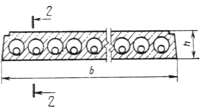

Plate type PG


Notes to hell 1-3
1. Slabs of types 1PKT, 2PKT, 3PKT, 1PKK, 2PKK and 3PKK can have technological bevels along all side faces.
2. Methods for strengthening the ends of the slabs are shown in Figures 1-3 as an example. It is permissible to use other methods of reinforcement, including reducing the diameter of the voids through one on both supports without sealing the opposite ends of the voids.
3. The dimensions and shape of the groove along the longitudinal upper edge of slabs of types 1PKT, 2PKT and 3PKT (Drawing 1b) and along the contour of slabs of type 4PK (Drawing 2) are established in the working drawings of the slabs.
4. In slabs intended for buildings (structures) with a calculated seismicity of 7-9 points, extreme voids may be absent due to the need to install embedded products or produce reinforcement for connections between slabs, walls, and anti-seismic belts.
table 2
|
Scope of application of plates |
Additional dimensions taken into account when determining the structural size of the slab, mm |
|||
|
length |
widthA 1 |
|||
|
A 1 |
A 2 |
A 3 | ||
|
Large-panel buildings, including buildings with a calculated seismicity of 7-9 points Buildings (structures) with walls made of bricks, stones and blocks, with the exception of buildings (structures) with a calculated seismicity of 7-9 points Buildings (structures) with walls made of bricks, stones and blocks with a calculated seismicity of 7-9 points Frame buildings (structures), including buildings (structures) with a calculated seismicity of 7-9 points |
10 - for slabs with a coordination width of less than 2400. 20 - for slabs with a coordination width of 2400 or more |
|||
1.2.5. Voids in slabs intended to be supported on two or three sides should be located parallel to the direction along which the length of the slabs is determined. In slabs intended to be supported on four sides, the voids should be located parallel to any side of the slab contour.
The nominal distance between the centers of voids in slabs (with the exception of slabs of types PG and PB) should be taken as no less than, mm:
185 - in slabs of types 1PK, 1PKT, 1PKK, 2PK, 2PKT, 2PKK, 3PK, 3PKT, 3PKK and 4PK;
235 - in slabs of type 5PK;
233 " " " 6pcs;
139 « « « 7pcs.
The distance between the centers of the voids of slabs of types PG and PB is determined in accordance with the parameters of the molding equipment of the manufacturer of these slabs.
1.2.6. The slabs should be made with recesses or grooves on the side edges to form, after embedding, intermittent or continuous keys that ensure the joint operation of the floor slabs for shear in the horizontal and vertical directions.
By agreement between the manufacturer and the consumer and the design organization - the author of the project for a specific building (structure), it is allowed to produce slabs without recesses or grooves for the formation of keys.
1.2.7. Slabs intended to be supported on two or three sides should be made prestressed. Slabs with a thickness of 220 mm, a length of less than 4780 mm, with voids with diameters of 159 and 140 mm and slabs with a thickness of 260 mm, with a length of less than 5680 mm, as well as slabs with a thickness of 220 mm, of any length, with voids with a diameter of 127 mm may be manufactured with non-prestressing reinforcement.
1.2.8. The slabs should be made with reinforced ends. Strengthening the ends is achieved by reducing the cross-section of the voids on the supports or filling the voids with concrete or concrete liners (Fig. 1-3). When the design load on the ends of the slabs in the wall support zone does not exceed 1.67 MPa (17 kgf/cm2), it is allowed, by agreement between the manufacturer and the consumer, to supply slabs with unreinforced ends.
Reinforcement methods and minimum dimensions of embedments are established in working drawings or indicated when ordering slabs.
1.2.9. In cases provided for by the working drawings of a particular building (structure), slabs may have embedded products, reinforcement outlets, local cutouts, holes and other additional structural details.
1.2.10. To lift and install slabs, mounting loops or special gripping devices are used, the design of which is established by the manufacturer in agreement with the consumer and the design organization - the author of the building (structure) project. The location and dimensions of the holes in the slabs intended for loopless installation are taken according to the drawings included in the design documentation of the gripping device for these slabs.
1.2.11. The consumption of concrete and steel on the slabs must correspond to those indicated in the working drawings of these slabs, taking into account possible clarifications made by the design organization in the prescribed manner.
1.2.12. The slabs are used taking into account their fire resistance limit specified in the working drawings of the slabs.
1.2.13. The slabs are designated by marks in accordance with the requirements of GOST 23009. The slab mark consists of alphanumeric groups separated by hyphens.
In the first group, indicate the designation of the type of slab, the length and width of the slab in decimeters, the values of which are rounded to the nearest whole number.
In the second group indicate:
the calculated load on the slab in kilopascals (kilogram-force per square meter) or the serial number of the slab in terms of bearing capacity;
steel class of prestressed reinforcement (for prestressed slabs);
type of concrete ( L - lightweight concrete, C - dense silicate concrete; heavy concrete is not indicated).
In the third group, if necessary, additional characteristics are indicated that reflect the special conditions of use of the slabs (for example, their resistance to aggressive gaseous media, seismic influences), as well as designations of the design features of the slabs (for example, the presence of additional embedded products).
EtcAndconditional measures indicatedAndI(grade) slab type 1PK with a length of 6280 mm, a width of 1490 mm, designed for a design load of 6 kPa, made of lightweight concrete with prestressed reinforcement of class At-V.
396.00 ₽
We have been distributing regulatory documents since 1999. We punch checks, pay taxes, accept all legal forms of payment without additional interest. Our clients are protected by law. LLC "CNTI Normocontrol"
Our prices are lower than other places because we work directly with document providers.
Delivery methods
- Express courier delivery (1-3 days)
- Courier delivery (7 days)
- Pickup from the Moscow office
- Russian Post
Applies to reinforced concrete hollow-core slabs made from heavy, light and dense silicate concrete and intended for the load-bearing part of the floors of buildings and structures for various purposes.
- Replaces GOST 26434-85 “Reinforced concrete floor slabs for residential buildings. Types and main parameters" regarding the types, main dimensions and parameters of reinforced concrete hollow-core slabs; IUS 2-1992
- Replaces GOST 9561-76 “Multi-hollow reinforced concrete panels for floors of buildings and structures. Technical specifications" IUS 2-1992
- Replaced by GOST 9561-2016 “Multi-hollow reinforced concrete floor slabs for buildings and structures. Technical specifications" IUS 4-2017
1 Technical requirements
2 Acceptance
3 Control methods
4 Transportation and storage
Appendix 3 (informative) Terms used in Appendix 2 and their explanations
This GOST is located in:
Organizations:
Reinforced concrete multihollow panels for floors in buildings. Specifications
- GOST 26433.0-85General provisions
- GOST 26433.1-89System for ensuring the accuracy of geometric parameters in construction. Rules for performing measurements. Factory-made elements
- GOST 8829-94Factory-made reinforced concrete and concrete building products. Load test methods. Rules for assessing strength, stiffness and crack resistance. Replaced by GOST 8829-2018.
- GOST 10922-90Welded reinforcement and embedded products, welded connections of reinforcement and embedded products of reinforced concrete structures. General technical conditions. Replaced by GOST 10922-2012.
- GOST 13015.0-83General technical requirements. Replaced by GOST 13015-2003.
- GOST 13015.1-81Prefabricated concrete and reinforced concrete structures and products. Acceptance. Replaced by GOST 13015-2003.
- GOST 13015.2-81Prefabricated concrete and reinforced concrete structures and products. Labeling. Replaced by GOST 13015-2003.
- GOST 13015.4-84Prefabricated concrete and reinforced concrete structures and products. Rules for transportation and storage. Replaced by GOST 13015-2003.
- GOST 17625-83Designs and products reinforced concrete. Radiation method for determining the thickness of the protective layer of concrete, the size and location of reinforcement
- GOST 22362-77Reinforced concrete structures. Methods for measuring the tensile force of reinforcement
- GOST 22904-93Reinforced concrete structures. Magnetic method for determining the thickness of the protective layer of concrete and the location of reinforcement
- GOST 23009-78Constructions and concrete and prefabricated reinforced concrete products. Symbols (brands). Replaced by GOST 23009-2016.
- GOST 23858-79Welded butt and tee connections for reinforced concrete structures. Ultrasonic quality control methods. Acceptance rules
- GOST 25697-83Plates balconies and loggias are reinforced concrete. General technical conditions. Replaced by GOST 25697-2018.
- GOST 26434-85Plates reinforced concrete floors for residential buildings. Types and basic parameters. Replaced by GOST 26434-2015.
- GOST 10180-90Concrete. Methods for determining strength using control samples. Replaced by GOST 10180-2012.
- GOST 10181.0-81Concrete mixtures. General requirements for test methods. Replaced by GOST 10181-2000.
- GOST 12730.0-78Concrete. General requirements for methods for determining density, humidity, water absorption, porosity and water resistance
- GOST 12730.1-78Concrete. Determination methods density
- GOST 12730.5-84Concrete. Determination methods waterproof. Replaced by GOST 12730.5-2018.
- GOST 17623-87Concrete. Radioisotope method for determining average density
- GOST 17624-87Concrete. Ultrasonic method for determining strength. Replaced by GOST 17624-2012.
- GOST 18105-86Concrete. Rules for strength control. Replaced by GOST 18105-2010.
- GOST 22690-88Concrete. Determination of strength by mechanical methods of non-destructive testing. Replaced by GOST 22690-2015.
- GOST 25214-82Silicate concrete is dense. Specifications
- GOST 26134-84Concrete. Ultrasonic method for determining frost resistance. Replaced by GOST 26134-2016.
- GOST 26633-91Concrete is heavy and fine-grained. Specifications. Replaced by GOST 26633-2012.
- GOST 5781-82Hot rolled steel for reinforcement of reinforced concrete structures. Specifications. Replaced by GOST 34028-2016.
- GOST 6727-80Wire from cold-drawn low-carbon steel for reinforcement of reinforced concrete structures. Specifications
- GOST 7348-81Wire from carbon steel for reinforcement of prestressed reinforced concrete structures. Specifications
- GOST 10884-94Reinforcing steel thermomechanically strengthened for reinforced concrete structures. Specifications. Replaced by GOST 34028-2016.
- GOST 13840-68Reinforcing steel ropes 1x7. Specifications
- GOST 25820-2000 . Replaced by GOST 25820-2014.
- GOST 8829-85Prefabricated concrete and reinforced concrete structures and products. Load test methods and evaluation of strength, stiffness and crack resistance. Replaced by GOST 8829-94.
- GOST 10181.3-81Concrete mixtures. Methods for determining porosity. Replaced by GOST 10181-2000.
- GOST 25820-83Concrete is lightweight. Specifications. Replaced by GOST 25820-2000.
- GOST 10060-87Concrete. Methods for determining frost resistance
- GOST 10884-81Reinforcing steel thermomechanically and thermally strengthened with a periodic profile. Specifications. Replaced by GOST 10884-94.
page 1

page 2

page 3

page 4

page 5

page 6

page 7

page 8

page 9

page 10

page 11

page 12

page 13

page 14

page 15

page 16

page 17

page 18

page 19

page 20

page 21

page 22
STATE STANDARD OF THE USSR UNION
REINFORCED CONCRETE FLOORS
MULTI-HOLLOW FOR BUILDINGS
AND STRUCTURES
TECHNICAL CONDITIONS
USSR STATE COMMITTEE FOR CONSTRUCTION
AND INVESTMENTS
Moscow
STATE STANDARD OF THE USSR UNION
Date of introduction 01/01/92
This standard applies to reinforced concrete hollow-core slabs (hereinafter referred to as slabs), made from heavy, light and dense silicate concrete and intended for the load-bearing part of the floors of buildings and structures for various purposes.
The slabs are used in accordance with the instructions of the working drawings of the slabs and additional requirements specified when ordering these structures.
1. TECHNICAL REQUIREMENTS
1.1. The slabs should be manufactured in accordance with the requirements of this standard and technological documentation approved by the manufacturer, according to working drawings of standard structures (see Appendix 1) or designs of buildings (structures).
It is allowed, by agreement between the manufacturer and the consumer, to produce slabs that differ in types and sizes from those given in this standard, subject to the remaining requirements of this standard.
1.2. Main parameters and dimensions
1.2.1. Plates are divided into types:
1PK - 220 mm thick with round voids with a diameter of 159 mm, designed for support on two sides;
1PKT - the same, for support on three sides;
1PKK - the same, for support on four sides;
2PK - 220 mm thick with round voids with a diameter of 140 mm, designed for support on two sides;
2PKT - the same, for support on three sides;
2PKK - the same for support on four sides;
3PK - 220 mm thick with round voids with a diameter of 127 mm, designed for support on two sides;
3PKT - the same, for support on three sides;
3PKK - the same, for support on four sides;
4PK - 260 mm thick with round voids with a diameter of 159 mm and cutouts in the upper zone along the contour, intended for support on both sides;
5PK - 260 mm thick with round voids with a diameter of 180 mm, designed for support on two sides;
6PK - 300 mm thick with round voids with a diameter of 203 mm, designed for support on two sides;
7PK - 160 mm thick with round voids with a diameter of 114 mm, designed for support on two sides;
PG - 260 mm thick with pear-shaped voids, designed for support on two sides;
PB - 220 mm thick, manufactured by continuous molding on long stands and designed to be supported on two sides.
1.2.2. The shape and coordination length and width of the slabs (except for PB type slabs) must correspond to those given in table. 1 and to hell. 1 - 3. For buildings (structures) with a calculated seismicity of 7 points or more, it is allowed to manufacture slabs having a shape different from that indicated in the drawing. 13.
1.2.3. The structural length and width of the slabs (except for PB type slabs) should be taken equal to the corresponding coordination size (Table 1), reduced by A 1 (gap between adjacent slabs) or A 2 (distance between adjacent slabs if there is a separating element between them, for example, an anti-seismic belt, ventilation ducts, crossbar ribs), or increased by A 3 (for example, for slabs supported by the entire thickness of the staircase walls of buildings with transverse load-bearing walls). Values A 1 , A 2 and A 3 are given in table. 2.
1.24. The shape and dimensions of PB type slabs must correspond to those established in the working drawings of the slabs, developed in accordance with the parameters of the molding equipment of the manufacturer of these slabs.
Table 1
|
Slab type |
Plate drawing number |
Coordination dimensions of the slab, mm |
|
|
From 2400 to 6600 inclusive. at intervals of 300, 7200, 7500 |
1000, 1200, 1500, 1800, 2400, 3000, 3600 |
||
|
1000, 1200, 1500 |
|||
|
From 3600 to 6600 inclusive. at intervals of 300, 7200, 7500 |
|||
|
From 2400 to 3600 inclusive. at intervals of 300 |
From 4800 to 6600 inclusive. at intervals of 300, 7200 |
||
|
From 2400 to 6600 inclusive. at intervals of 300, 7200, 9000 |
1000, 1200, 1500 |
||
|
6000, 9000, 12000 |
1000, 1200, 1500 |
||
|
1000, 1200, 1500 |
|||
|
From 3600 to 6300 inclusive. at intervals of 3000 |
1000, 1200, 1500, 1800 |
||
|
6000, 9000, 12000 |
1000, 1200, 1500 |
||
Note. The length of the slabs is taken to be:
size of the side of the slab not supported by bearing structures buildings (structures) - for slabs intended to be supported on two or three sides;
the smaller size of the slab in plan - for slabs intended to be supported along the contour.
Plates types 1PK, 2PK, 3PK, 5PK, 6PK, 7PK
Plates types 1PKT, 2PKT, 3PKT
Plates of types 1PKK, 2PKK, 3PKK
Plate type 4pcs
Plate type PG
Notes to hell. 13
1. Slabs of types 1PKT, 2PKT, 3PKT, 1PKK, 2PKK and 3PKK can have technological bevels along all side faces.
2. Methods for strengthening the ends of the slabs are shown in Fig. 1 - 3 as an example. It is allowed to use other methods of reinforcement, including reducing the diameter of the voids through one on both supports without sealing the opposite ends of the voids.
3. The dimensions and shape of the groove along the longitudinal upper edge of slabs of types 1PKT, 2PKT and 3PKT (Drawing 1 b) and along the contour of slabs of type 4PK (Drawing 2) are established in the working drawings of the slabs.
4. In slabs intended for buildings (structures) with a design seismicity of 7 - 9 points, extreme voids may be absent due to the need to install embedded products or produce reinforcement for connections between slabs, walls, and anti-seismic belts.
table 2
|
Scope of application of plates |
Additional dimensions taken into account when determining the structural size of the slab, mm |
|||
|
width A 1 |
||||
|
Large-panel buildings, including buildings with a calculated seismicity of 7 - 9 points |
10 - for slabs with a coordination width of less than 2400. 20 - for slabs with a coordination width of 2400 or more |
|||
|
Buildings (structures) with walls made of bricks, stones and blocks, with the exception of buildings (structures) with a calculated seismicity of 7 - 9 points |
||||
|
Buildings (structures) with walls made of bricks, stones and blocks with a calculated seismicity of 7 - 9 points |
||||
|
Frame buildings(structures), including buildings (structures) with a calculated seismicity of 7 - 9 points |
||||
1.2.5. Voids in slabs intended to be supported on two or three sides should be located parallel to the direction along which the length of the slabs is determined. In slabs intended to be supported on four sides, the voids should be located parallel to any side of the slab contour.
The nominal distance between the centers of voids in slabs (except for slabs of types PG and PB) should be taken as no less than, mm:
185 - in slabs of types 1PK, 1PKT, 1PKK, 2PK, 2PKT, 2PKK, 3PK, 3PKT, 3PKK and 4PK;
235 - in slabs of type 5PK;
233 " " " 6pcs;
139 « « « 7pcs.
The distance between the centers of the voids of slabs of types PG and PB is determined in accordance with the parameters of the molding equipment of the manufacturer of these slabs.
1.2.6. The slabs should be made with recesses or grooves on the side faces to form, after embedding, intermittent or continuous keys that ensure the joint operation of the floor slabs for shear in the horizontal and vertical directions.
By agreement between the manufacturer and the consumer and the design organization - the author of the project for a specific building (structure), it is allowed to produce slabs without recesses or grooves for the formation of keys.
1.2.7. Slabs intended to be supported on two or three sides should be made prestressed. Slabs with a thickness of 220 mm, a length of less than 4780 mm, with voids with diameters of 159 and 140 mm and slabs with a thickness of 260 mm, with a length of less than 5680 mm, as well as slabs with a thickness of 220 mm, of any length, with voids with a diameter of 127 mm may be manufactured with non-prestressing reinforcement.
1.2.8. The slabs should be made with reinforced ends. Strengthening the ends is achieved by reducing the cross-section of the voids on the supports or filling the voids with concrete or concrete liners (Fig. 1 - 3). When the design load on the ends of the slabs in the wall support zone does not exceed 1.67 MPa (17 kgf/cm2), it is allowed, by agreement between the manufacturer and the consumer, to supply slabs with unreinforced ends.
Reinforcement methods and minimum dimensions of embedments are established in working drawings or indicated when ordering slabs.
1.2.9. In cases provided for by the working drawings of a particular building (structure), slabs may have embedded products, reinforcement outlets, local cutouts, holes and other additional structural details.
1.2.10. To lift and install slabs, mounting loops or special gripping devices are used, the design of which is established by the manufacturer in agreement with the consumer and the design organization - the author of the building (structure) project. The location and dimensions of the holes in the slabs intended for loopless installation are taken according to the drawings included in the design documentation of the gripping device for these slabs.
1.2.11. The consumption of concrete and steel on the slabs must correspond to those indicated in the working drawings of these slabs, taking into account possible clarifications made by the design organization in the prescribed manner.
1.2.12. The slabs are used taking into account their fire resistance limit specified in the working drawings of the slabs.
1.2.13. The slabs are marked with marks in accordance with the requirements of GOST 23009. The slab brand consists of alphanumeric groups separated by hyphens.
In the first group, indicate the designation of the type of slab, the length and width of the slab in decimeters, the values of which are rounded to the nearest whole number.
In the second group indicate:
the calculated load on the slab in kilopascals (kilogram-force per square meter) or the serial number of the slab in terms of bearing capacity;
steel class of prestressed reinforcement (for prestressed slabs);
type of concrete (L - lightweight concrete, C - dense silicate concrete; heavy concrete is not indicated).
In the third group, if necessary, additional characteristics are indicated that reflect the special conditions of use of the slabs (for example, their resistance to aggressive gaseous media, seismic influences), as well as designations of the design features of the slabs (for example, the presence of additional embedded products).
An example of a symbol (brand) of a 1PK type slab with a length of 6280 mm, a width of 1490 mm, designed for a design load of 6 kPa, made of lightweight concrete with prestressed reinforcement of class At-V:
1PK63.15-6A T VL
The same, made of heavy concrete and intended for use in buildings with a calculated seismicity of 7 points:
1PK63.15-6A T V-C7
Note. It is allowed to accept the designation of slab brands in accordance with the working drawings of the slabs until they are revised.
1.3. Characteristics
1.3.1. The slabs must meet the requirements established during the design for strength, rigidity, crack resistance, and when tested by loading in the cases provided for in the working drawings, withstand control loads.
1.3.2. The slabs must meet the requirements of GOST 13015.0:
according to the actual strength of concrete (at design age, transfer and tempering);
on the frost resistance of concrete, and for slabs operated under conditions of exposure to an aggressive gaseous environment - also on the water resistance of concrete;
according to the average density of lightweight concrete;
to steel grades for reinforcing and embedded products, including mounting loops;
by deviations in the thickness of the protective layer of concrete to the reinforcement;
for corrosion protection.
Slabs used as the load-bearing part of loggias must also meet the additional requirements of GOST 25697.
1.3.3. Slabs should be made of heavy concrete in accordance with GOST 26633, structural lightweight concrete of a dense structure with an average density of at least 1400 kg/m 3 in accordance with GOST 25820 or dense silicate concrete with an average density of at least 1800 kg/m 3 in accordance with GOST 25214 classes or grades of compressive strength indicated in the working drawings of these slabs.
1.3.4. Compression forces (releasing the tension of the reinforcement) are transferred to the concrete after it reaches the required transfer strength.
The normalized transfer strength of concrete of prestressed slabs, depending on the class or grade of concrete in terms of compressive strength, the type and class of prestressed reinforcing steel, must correspond to that indicated in the working drawings of these slabs.
1.3.5. The normalized tempering strength of concrete for prestressed slabs made of heavy or light concrete for the warm season should be equal to the normalized transfer strength of concrete, and for slabs with non-prestressed reinforcement - 70% of the compressive strength of concrete corresponding to its class or grade. When delivering these slabs in the cold season or to ensure their safety during transportation by rail in the warm season (by agreement between the manufacturer and consumer of the slabs), the normalized tempering strength of concrete can be increased to 85% of the compressive strength of concrete corresponding to its class or grade .
The normalized tempering strength of concrete for slabs made of dense silicate concrete should be equal to 100% of the compressive strength of concrete corresponding to its class or grade.
1.3.6. Reinforcing steel should be used to reinforce slabs the following types and classes:
as prestressed reinforcement - thermomechanically strengthened rod of classes At-IV, At-V and At-VI according to GOST 10884 (regardless of weldability and increased resistance to corrosion cracking of the reinforcement), hot-rolled rod of classes A-IV, A-V and A-VI according to GOST 5781, reinforcing ropes of class K-7 according to GOST 13840, high-strength periodic wire of class VR-II according to GOST 7348, wire of class VR-600 according to TU 14-4-1322 and rod reinforcement of class A-IIIb, made of reinforcing steel class A-I II according to GOST 5781, reinforced by drawing with control of the stress value and ultimate elongation;
as non-prestressing reinforcement - hot-rolled rod of periodic profile of classes A-II, A-III and smooth class A-I according to GOST 5781, periodic wire of class BP-I according to GOST 6727 and class BP-600 according to TU 14-4-1322.
In slabs produced by continuous formless molding on long stands, continuous reinforcement, and also using multi-temperature electrothermal tension, high-strength wire reinforcement is used in accordance with GOST 7348 and ropes in accordance with GOST 13840.
1.3.7. The shape and dimensions of reinforcement and embedded products and their position in the slabs must correspond to those indicated in the working drawings of these slabs.
1.3.8. Welded reinforcement and embedded products must comply with the requirements of GOST 10922.
1.3.9. The stress values in the prestressing reinforcement, monitored after tensioning it on the stops, must correspond to those indicated in the working drawings of the slabs.
The values of actual stress deviations in prestressed reinforcement should not exceed the limits specified in the working drawings of the slabs.
1.3.10 The values of actual deviations of the geometric parameters of the slabs should not exceed the limits specified in the table. 3.
Table 3
|
Name of deviation of geometric parameter |
Name of geometric parameter |
Prev. off |
|
Deviation from linear size |
Slab length and width: |
|
|
up to 2500 incl. |
||
|
St. 2500 to 4000 incl. |
||
|
St. 4000 to 8000 incl. |
||
|
Slab thickness |
||
|
Position size: |
||
|
holes and cutouts |
||
|
embedded products: |
||
|
in the plane of the slab |
||
|
from the plane of the slab |
||
|
Deviation from straightness of the profile of the upper surface of the slab, intended for direct gluing of linoleum, as well as the profile of the side faces of the slab at a length of 2000 |
||
|
Deviation from the flatness of the front lower (ceiling) surface of the slab when measured from a conventional plane passing through three corner points of the slab with a length of: |
||
* The deviation from the size that determines the position of the embedded product from the upper plane of the slabs intended for direct gluing of linoleum should only be inside the slab.
1.3.11. Requirements for the quality of concrete surfaces and the appearance of slabs (including requirements for the permissible opening width of technological cracks) - in accordance with GOST 13015.0 and this standard.
13.12. The quality of concrete slab surfaces must meet the requirements established for the categories:
A3 - lower (ceiling);
A7 - top and side.
By agreement between the manufacturer and the consumer, the following categories of surfaces can be installed instead of the indicated ones:
A2 - lower (ceiling), prepared for painting;
A4 - the same, prepared for wallpapering or decorative finishing with paste-like compounds, and the top, prepared for covering with linoleum;
A6 - lower (ceiling), for which there are no requirements for the quality of finishing.
1.3.13. In the concrete of slabs supplied to the consumer, cracks are not allowed, with the exception of shrinkage and other surface technological cracks with a width of no more than 0.3 mm on the top surface of the slabs and no more than 0.2 mm on the side and bottom surfaces of the slabs.
1.3.14. Exposure of reinforcement is not allowed, with the exception of reinforcement outlets or ends of prestressing reinforcement, which should not protrude beyond the end surfaces of the slabs by more than 10 mm and should be protected with a layer of cement-sand mortar or bitumen varnish.
1.4. Marking
2.3. Slabs in terms of the accuracy of geometric parameters, the thickness of the protective layer of concrete before the reinforcement, the width of the opening of technological cracks and the category of the concrete surface should be accepted based on the results of random inspection.
2.4. The porosity (volume of intergranular voids) of a compacted mixture of lightweight concrete should be determined at least once a month.
2.5. The document on the quality of slabs intended for use in conditions of exposure to aggressive environments must additionally indicate the grade of concrete for water resistance (if this indicator is specified in the order for the production of slabs).
3. CONTROL METHODS
3.1. Load tests of slabs to control their strength, rigidity and crack resistance should be carried out in accordance with the requirements of GOST 8829 and working drawings of these slabs.
3.2. The strength of concrete slabs should be determined according to GOST 10180 on a series of samples made from a concrete mixture of the working composition and stored under the conditions established by GOST 18105.
When determining the strength of concrete using non-destructive testing methods, the actual transfer and tempering compressive strength of concrete is determined by the ultrasonic method according to GOST 17624 or by mechanical devices according to GOST 22690. It is permissible to use other non-destructive testing methods provided for in the standards for concrete testing methods.
3.3. The frost resistance of concrete slabs should be determined according to GOST 10060 or by the ultrasonic method according to GOST 26134 on a series of samples made from a concrete mixture of the working composition.
3.4. The water resistance of concrete slabs intended for operation in conditions of exposure to aggressive environments should be determined according to GOST 12730.0 and GOST 12730.5.
3.5. The average density of light and dense silicate concrete should be determined according to GOST 12730.0 and GOST 12730.1 or by the radioisotope method according to GOST 17623.
3.6. The porosity indicators of a compacted mixture of lightweight concrete should be determined according to GOST 10181.0 and GOST 10181.3.
3.7. Inspection of welded reinforcement and embedded products - in accordance with GOST 10922 and GOST 23858.
3.8. The tension force of the reinforcement, controlled at the end of the tension, is measured according to GOST 22362.
3.9. The dimensions of the slabs, deviations from the straightness and flatness of the surfaces of the slabs, the width of the opening of technological cracks, the sizes of cavities, sagging and edges of concrete slabs should be determined by the methods established by GOST 26433.0 and GOST 26433.1.
3.10. The dimensions and position of reinforcement and embedded products, as well as the thickness of the protective layer of concrete before the reinforcement should be determined according to GOST 17625 and GOST 22904. With absence necessary devices It is allowed to cut down grooves and expose the slab reinforcement with subsequent sealing of the grooves. Furrows should be punched at a distance from the ends not exceeding 0.25 times the length of the slab.
4. TRANSPORTATION AND STORAGE
4.1. Transportation and storage of slabs - in accordance with GOST 13015.4 and this standard.
4.2. The slabs should be transported and stored in stacks laid in a horizontal position.
On specialized vehicles it is allowed to transport slabs in an inclined or vertical position.
4.3. The height of the stack of slabs should not be more than 2.5 m.
4.4. Pads for the bottom row of slabs and spacers between them in a stack should be located near the mounting loops.
ANNEX 1
LIST OF SIZES AND SERIES OF WORKING DRAWINGS OF PLATES FOR MASSIVE APPLICATION
Table 4
|
Slab size |
Designation of a series of working drawings of slabs |
|
1.241-1; 1.090.1-1; 1.090.1-2s; 1.090.1-3pv; 1.090.1-5s |
|
|
1.241-1; 1.090.1-1 |
|
|
1.141-1; 1.141.1-33s |
|
|
1.141-1; 1.141.1-30; 1.141.1-33s |
|
|
1.141-1; 1.141.1-33s |
|
|
1.141-18s; 1.141.1-25s; 1.141.1-32s |
|
|
1.141-1; 1.141.1-33s |
|
|
1.141-1; 1.141.1-33с; 1.090.1-2s; 1.090.1-3pv; 1.090.1-5s |
|
|
1.141-1; 1.141.1-33s |
|
|
1.141-18s; 1.141.1-25s; 1.141.1-32s |
|
|
1.141-1; 1.141.1-33s |
|
|
1.141-1; 1.141.1-33s |
|
|
1.141-1; 1.141.1-33с; 1.141.1-30 |
|
|
1.141-1; 1.141.1-33s |
|
|
1.141-1; 1.141.1-33s |
|
|
1.141.1; 1.141.1-33с; 1.141.1-30 |
|
|
1.141-1; 1.141.1-33s |
|
|
1.141-18s; 1.141.1-25s; 1.141.1-32s |
|
|
1.141-1; 1.090.1-1; 1.090.1-2s; 1.090.1-3pv; 1.090.1-5s |
STATE STANDARD
USSR UNION
MULTI-HOLLOW FOR BUILDINGS
AND STRUCTURES
TECHNICAL CONDITIONS
GOST 9561-91
Official publication
USSR STATE COMMITTEE FOR CONSTRUCTION
AND INVESTMENTS
GSTATE STANDARD OF THE USSR UNION
REINFORCED CONCRETE FLOORS
MULTI-HOLLOW FOR BUILDINGS AND
STRUCTURES GOST
Specifications 9561-91
Reinforced concrete multihollow panels
for floors in buildings. Specifications
___________________________________________________________
Date of introduction 01/01/92
This standard applies to reinforced concrete hollow-core slabs (hereinafter referred to as slabs), made from heavy, light and dense silicate concrete and intended for the load-bearing part of the floors of buildings and structures for various purposes.
The slabs are used in accordance with the instructions of the working drawings of the slabs and additional requirements specified when ordering these structures.
1 . TECHNICAL REQUIREMENTS
1.1. The slabs should be manufactured in accordance with the requirements of this standard and technological documentation approved by the manufacturer, according to working drawings of standard structures (see Appendix 1) or designs of buildings (structures).
It is allowed, by agreement between the manufacturer and the consumer, to produce slabs that differ in types and sizes from those given in this standard, subject to the remaining requirements of this standard.
1.2. Main parameters and dimensions
1.2.1. Plates are divided into types:
1 PC - 220 mm thick with round voids with a diameter of 159 mm. designed to be supported on two sides;
1PKT - the same, for support on three sides;
1PKK - the same, for support on four sides;
2PK - 220 mm thick with round voids with a diameter of 140 mm, designed for support on two sides;
2PKT - the same, for support on three sides;
2PKK - the same for support on four sides;
3 pcs - 220 mm thick with round hollows with a diameter of 127 mm, designed to be supported on two sides;
3PKT - the same, for support on three sides;
3PKK - the same, for support on four sides;
4PCs, 260 mm thick, with round voids with a diameter of 159 mm and cutouts in the upper zone along the contour, designed for support on both sides;
5PK - 260 mm thick with round voids with a diameter of 180 mm, designed for support on two sides;
6pcs - 300 mm thick with round voids with a diameter of 203 mm, designed for support on two sides;
7PK - 160 mm thick with round voids with a diameter of 114 mm, designed for support on two sides;
PG - 260 mm thick with pear-shaped voids, designed for support on two sides;
PB - 220 mm thick, manufactured by continuous molding on long stands and designed to be supported on two sides.
1.2.2. The shape and coordination length and width of the slabs (with the exception of PB type slabs) must correspond to those given in the table. 1 and to hell. 1-3. For buildings (structures) with a calculated seismicity of 7 points or more, it is allowed to manufacture slabs having a shape different from that indicated in the drawing. 1-3.
1.2.3. The structural length and width of the slabs (except for PB type slabs) should be taken equal to the corresponding coordination size (Table 1), reduced by A 1 (gap between adjacent slabs) or A 2 (distance between adjacent slabs if there is a separating element between them, for example, an anti-seismic belt, ventilation ducts, crossbar ribs), or increased by A 3 (for example, for slabs supported by the entire thickness of the staircase walls of buildings with transverse load-bearing walls). Values A 1 ,A 2 and A 3 , are given in table. 2.
1.2 4. The shapes and dimensions of PB type slabs must correspond to those established in the working drawings of the slabs, developed in accordance with the parameters of the molding equipment of the manufacturer of these slabs.
Table 1
|
Drawing number |
Coordination dimensions of the slab, mm |
||
|
slabs |
slabs |
Length |
Width |
|
From 2400 to 6600 inclusive. at intervals of 300, 7200, 7500 |
1000, 1200, 1500, 1800, 2400, 3000, 3600 |
||
|
1000, 1200, 1500 |
|||
|
From 3600 to 6600 inclusive. at intervals of 300, 7200, 7500 | |||
|
From 2400 to 3600 inclusive. at intervals of 300 |
From 4800 to 6600 inclusive. at intervals of 300, 7200 |
||
|
From 2400 to 6600 inclusive. at intervals of 300, 7200, 9000 |
1000, 1200, 1500 |
||
|
6000, 9000, 12000 |
1000, 1200, 1500 |
||
|
1000, 1200, 1500 |
|||
|
From 3600 to 6300 inclusive. at intervals of 3000 |
1000, 1200, 1500, 1800 |
||
|
6000, 9000, 12000 |
1000, 1200, 1500 |
||
Note. The length of the slabs is taken to be:
the size of the side of the slab not supported by the load-bearing structures of the building (structure) - for slabs intended to be supported on two or three sides;
the smaller size of the slab in plan - for slabs intended to be supported along the contour.
Plates types 1PK, 2PK, 3PK, 5PK, 6PK, 7PK