The main element of the roof, which absorbs and resists all types of loads, is rafter system. Therefore, in order for your roof to reliably withstand all impacts environment, it is very important to do correct calculation rafter system.
To independently calculate the characteristics of the materials required for installing the rafter system, I provide simplified calculation formulas. Simplifications have been made to increase the strength of the structure. This will cause a slight increase in lumber consumption, but small roofs for individual buildings it will be insignificant. These formulas can be used when calculating gable attic and mansard roofs, as well as single-pitch roofs.
Based on the calculation methodology given below, programmer Andrey Mutovkin (Andrey’s business card - mutovkin.rf) for his own needs developed a rafter system calculation program. At my request, he generously allowed me to post it on the site. You can download the program.
The calculation methodology is based on SNiP 2.01.07-85 “Loads and Impacts”, taking into account “Changes...” from 2008, as well as on the basis of formulas given in other sources. I developed this technique many years ago, and time has confirmed its correctness.
To calculate the rafter system, first of all, it is necessary to calculate all the loads acting on the roof.
I. Loads acting on the roof.
1. Snow loads.
2. Wind loads.
In addition to the above, the rafter system is also subject to loads from roof elements:
3. Roof weight.
4. Weight of rough flooring and sheathing.
5. Weight of insulation (in the case of an insulated attic).
6. The weight of the rafter system itself.
Let's consider all these loads in more detail.
1. Snow loads.
To calculate the snow load we use the formula:
Where,
S - desired value of snow load, kg/m²
µ - coefficient depending on the roof slope.
Sg - standard snow load, kg/m².
µ - coefficient depending on the roof slope α. Dimensionless quantity.
The roof slope angle α can be approximately determined by dividing the height H by half the span - L.
The results are summarized in the table:
Then, if α is less than or equal to 30°, µ = 1 ;
if α is greater than or equal to 60°, µ = 0;
If 30° is calculated using the formula:
µ = 0.033·(60-α);
Sg - standard snow load, kg/m².
For Russia it is accepted according to map 1 of mandatory appendix 5 of SNiP 2.01.07-85 “Loads and impacts”
For Belarus, the standard snow load Sg is determined
Technical code of PRACTICE Eurocode 1. EFFECTS ON STRUCTURES Part 1-3. General impacts. Snow loads. TKP EN1991-1-3-2009 (02250).
For example,
Brest (I) - 120 kg/m²,
Grodno (II) - 140 kg/m²,
Minsk (III) - 160 kg/m²,
Vitebsk (IV) - 180 kg/m².
Find the maximum possible snow load on a roof with a height of 2.5 m and a span of 7 m.
The building is located in the village. Babenki Ivanovo region. RF.
Using Map 1 of Mandatory Appendix 5 of SNiP 2.01.07-85 “Loads and Impacts” we determine Sg - the standard snow load for the city of Ivanovo (IV district):
Sg=240 kg/m²
Determine the roof slope angle α.
To do this, divide the roof height (H) by half the span (L): 2.5/3.5=0.714
and from the table we find the slope angle α=36°.
Since 30°, the calculation µ will be produced using the formula µ = 0.033·(60-α) .
Substituting the value α=36°, we find: µ = 0.033·(60-36)= 0.79
Then S=Sg·µ =240·0.79=189kg/m²;
the maximum possible snow load on our roof will be 189 kg/m².
2. Wind loads.
If the roof is steep (α > 30°), then due to its windage, the wind puts pressure on one of the slopes and tends to overturn it.
If the roof is flat (α, then the lifting aerodynamic force that arises when the wind bends around it, as well as turbulence under the overhangs, tend to lift this roof.
According to SNiP 2.01.07-85 “Loads and impacts” (in Belarus - Eurocode 1 IMPACTS ON STRUCTURES Part 1-4. General impacts. Wind impacts), the standard value of the average component of the wind load Wm at a height Z above the ground surface should be determined by the formula :
Where,
Wo is the standard value of wind pressure.
K is a coefficient that takes into account the change in wind pressure with height.
C - aerodynamic coefficient.
K is a coefficient that takes into account the change in wind pressure with height. Its values, depending on the height of the building and the nature of the terrain, are summarized in Table 3.
C - aerodynamic coefficient,
which, depending on the configuration of the building and the roof, can take values from minus 1.8 (the roof rises) to plus 0.8 (the wind presses on the roof). Since our calculation is simplified in the direction of increasing strength, we take the value of C equal to 0.8.
When building a roof, it must be remembered that wind forces tending to lift or tear off the roof can reach significant values, and therefore, the bottom of each rafter leg must be properly attached to the walls or mats.
This can be done by any means, for example, using annealed (for softness) steel wire with a diameter of 5 - 6 mm. With this wire, each rafter leg is screwed to the matrices or to the ears of the floor slabs. It's obvious that The heavier the roof, the better!
Determine the average wind load on the roof one-story house with the height of the ridge from the ground - 6 m. , slope angle α=36° in the village of Babenki, Ivanovo region. RF.
According to map 3 of Appendix 5 in “SNiP 2.01.07-85” we find that the Ivanovo region belongs to the second wind region Wo= 30 kg/m²
Since all buildings in the village are below 10m, coefficient K= 1.0
The value of the aerodynamic coefficient C is taken equal to 0.8
standard value of the average component of the wind load Wm = 30 1.0 0.8 = 24 kg/m².
For information: if the wind blows at the end of a given roof, then a lifting (tearing) force of up to 33.6 kg/m² acts on its edge
3. Roof weight.
Different types of roofing have the following weight:
1. Slate 10 - 15 kg/m²;
2. Ondulin (bitumen slate) 4 - 6 kg/m²;
3. Ceramic tiles 35 - 50kg/m²;
4. Cement-sand tiles 40 - 50 kg/m²;
5. Bituminous shingles 8 - 12 kg/m²;
6. Metal tiles 4 - 5 kg/m²;
7. Corrugated sheeting 4 - 5 kg/m²;
4. Weight of rough flooring, sheathing and rafter system.
The weight of the rough flooring is 18 - 20 kg/m²;
Sheathing weight 8 - 10 kg/m²;
The weight of the rafter system itself is 15 - 20 kg/m²;
When calculating the final load on the rafter system, all of the above loads are summed up.
Now I’ll tell you a little secret. Sellers of some types of roofing materials note their lightness as one of the positive properties, which, according to them, will lead to significant savings in lumber in the manufacture of the rafter system.
To refute this statement, I will give the following example.
Calculation of the load on the rafter system when using various roofing materials.
Let's calculate the load on the rafter system when using the heaviest one (Cement-sand tiles
50 kg/m²) and the lightest (Metal tile 5 kg/m²) roofing material for our house in the village of Babenki, Ivanovo region. RF.
Cement-sand tiles:
Wind loads - 24kg/m²
Roof weight - 50 kg/m²
Sheathing weight - 20 kg/m²
Total - 303 kg/m²
Metal tiles:
Snow load - 189kg/m²
Wind loads - 24kg/m²
Roof weight - 5 kg/m²
Sheathing weight - 20 kg/m²
The weight of the rafter system itself is 20 kg/m²
Total - 258 kg/m²
Obviously, the existing difference in design loads (only about 15%) cannot lead to any significant savings in lumber.
So, we figured out the calculation of the total load Q acting per square meter of roof!
I especially draw your attention: when making calculations, pay close attention to the dimensions!!!
II. Calculation of the rafter system.
Rafter system consists of separate rafters ( rafter legs), therefore the calculation comes down to determining the load on each rafter leg separately and calculating the cross-section of an individual rafter leg.
1. Find the distributed load on linear meter each rafter leg.
Where
Qr - distributed load per linear meter of rafter leg - kg/m,
A - distance between rafters (rafter pitch) - m,
Q is the total load acting on a square meter of roof - kg/m².
2. We determine the working section of the maximum length Lmax in the rafter leg.
3. We count minimum section rafter leg material.
When choosing material for rafters, we are guided by the table of standard sizes of lumber (GOST 24454-80 Lumber coniferous species. Dimensions), which are summarized in Table 4.
| Board thickness - section width (B) | Board width - section height (H) | ||||||||
|---|---|---|---|---|---|---|---|---|---|
| 16 | 75 | 100 | 125 | 150 | |||||
| 19 | 75 | 100 | 125 | 150 | 175 | ||||
| 22 | 75 | 100 | 125 | 150 | 175 | 200 | 225 | ||
| 25 | 75 | 100 | 125 | 150 | 175 | 200 | 225 | 250 | 275 |
| 32 | 75 | 100 | 125 | 150 | 175 | 200 | 225 | 250 | 275 |
| 40 | 75 | 100 | 125 | 150 | 175 | 200 | 225 | 250 | 275 |
| 44 | 75 | 100 | 125 | 150 | 175 | 200 | 225 | 250 | 275 |
| 50 | 75 | 100 | 125 | 150 | 175 | 200 | 225 | 250 | 275 |
| 60 | 75 | 100 | 125 | 150 | 175 | 200 | 225 | 250 | 275 |
| 75 | 75 | 100 | 125 | 150 | 175 | 200 | 225 | 250 | 275 |
| 100 | 100 | 125 | 150 | 175 | 200 | 225 | 250 | 275 | |
| 125 | 125 | 150 | 175 | 200 | 225 | 250 | |||
| 150 | 150 | 175 | 200 | 225 | 250 | ||||
| 175 | 175 | 200 | 225 | 250 | |||||
| 200 | 200 | 225 | 250 | ||||||
| 250 | 250 |
A. We calculate the cross-section of the rafter leg.
We set the section width arbitrarily in accordance with standard sizes, and the height of the section is determined by the formula:
H ≥ 8.6 Lmax sqrt(Qr/(BRben)), if the roof slope α
H ≥ 9.5 Lmax sqrt(Qr/(BRben)), if the roof slope α > 30°.
H - section height cm,
B - section width cm,
Rbend - bending resistance of wood, kg/cm².
For pine and spruce Rben is equal to:
1st grade - 140 kg/cm²;
2nd grade - 130 kg/cm²;
3rd grade - 85 kg/cm²;
sqrt - square root
B. We check whether the deflection value is within the standard.
The normalized deflection of the material under load for all roof elements should not exceed L/200. Where, L is the length of the working section.
This condition is satisfied if the following inequality is true:
3.125 Qr (Lmax)³/(B H³) ≤ 1
Where,
Qr - distributed load per linear meter of rafter leg - kg/m,
Lmax - working section of the rafter leg with maximum length m,
B - section width cm,
H - section height cm,
If the inequality is not met, then increase B or H.
Condition:
Roof pitch angle α = 36°;
Rafter pitch A= 0.8 m;
The working section of the rafter leg of maximum length Lmax = 2.8 m;
Material - 1st grade pine (Rbending = 140 kg/cm²);
Roofing - cement-sand tiles (Roofing weight - 50 kg/m²).
As it was calculated, the total load acting on a square meter of roof is Q = 303 kg/m².
1. Find the distributed load per linear meter of each rafter leg Qr=A·Q;
Qr=0.8·303=242 kg/m;
2. Choose the thickness of the board for the rafters - 5 cm.
Let's calculate the cross-section of the rafter leg with a section width of 5 cm.
Then, H ≥ 9.5 Lmax sqrt(Qr/BRben), since the roof slope α > 30°:
H ≥ 9.5 2.8 sqrt(242/5 140)
H ≥15.6 cm;
From the table of standard sizes of lumber, select a board with the closest cross-section:
width - 5 cm, height - 17.5 cm.
3. We check whether the deflection value is within the standard. To do this, the following inequality must be observed:
3.125 Qr (Lmax)³/B H³ ≤ 1
Substituting the values, we have: 3.125·242·(2.8)³ / 5·(17.5)³= 0.61
Meaning 0.61, which means the cross-section of the rafter material is chosen correctly.
The cross-section of the rafters, installed in increments of 0.8 m, for the roof of our house will be: width - 5 cm, height - 17.5 cm.
Specify the parameters of wooden rafters:
B– width of the rafters, important parameter determining the reliability of the rafter system. The required rafter section (in particular width) depends on: loads (constant - the weight of the sheathing and roofing pie, as well as temporary - snow, wind), the material used (quality and its type: board, timber, laminated timber), the length of the rafter leg, the distance between the rafters. You can determine the approximate cross-section of the beam for the rafters using the table data (the width value is the larger value from column 3, for example, with a rafter length of up to 3000 mm and a pitch of 1200 mm, the desired width value is 100 mm). When choosing the width of the rafters, be sure to take into account the recommendations given in SP 64.13330.2011 “ Wooden structures"and SP 20.13330.2011 "Loads and impacts".
| Rafter length, mm | Rafter pitch, mm | Rafter section, mm |
| Up to 3000 mm | 1200 | 80x100 |
| Up to 3000 mm | 1800 | 90x100 |
| Up to 4000 mm | 1000 | 80x160 |
| Up to 4000 mm | 1400 | 80x180 |
| Up to 4000 mm | 1800 | 90x180 |
| Up to 6000 mm | 1000 | 80x200 |
| Up to 6000 mm | 1400 | 100x200 |
Y– roof height, distance from the ridge to the attic floor. Affects the angle of inclination of the roof. If you plan to arrange non-residential attic, should choose small height(less material will be required for rafters, waterproofing and roofing), but sufficient for inspection and maintenance (at least 1500 mm). If it is necessary to equip a living space under the roof arch, to determine its height, you must focus on the height of the tallest family member plus 400-500 mm (approximately 1900-2500 mm). In any case, you must also take into account the requirements of SP 20.13330.2011 (updated edition of SNiP 2.01.07-85*). It should be remembered that on a roof with a small angle of inclination (small height) precipitation can be retained, which negatively affects its tightness and durability. However, a high roof becomes more vulnerable to strong wind gusts. The optimal tilt angle is between 30-45 degrees.
X– The width of the roof (without overhangs) is determined by the width of the outer perimeter of your house.
C– size of overhang, important structural element roof, protecting the walls and foundation from precipitation, is determined taking into account the climatic conditions of your region (SP 20.13330.2011) and general architectural idea. For one and two-story houses without organizing external water flow of at least 600 mm. If you arrange a drainage system, you can reduce it to 400 mm (SNB 3.02.04-03). According to the requirements of IRC-2012, paragraph R802.7.1.1 (International Building Code for 1-2 unit individual residential buildings) maximum length free overhang of rafters, which does not require the installation of additional support struts, 610 mm. The optimal overhang size is considered to be 500 mm.
Z– this is the distance from the top edge of the rafter to the cut. Size Z is related to the width of the rafter by a simple ratio - no more than 2/3 of its width (neglecting this rule significantly reduces the load-bearing capacity of the rafter). The cut is necessary to attach the rafters to the mauerlat - a support that takes the load from the roof and redistributes it to the load-bearing walls.
By checking the “Black and white drawing” option, you will receive a drawing that is close to GOST requirements and will be able to print it without wasting color paint or toner.
Calculation results:
Length to rafter overhang– this size should be used to mark the cut of the rafters to the mauerlat.
Overhang length will show how far it is necessary to extend the rafter beyond the perimeter of the house to obtain a given roof overhang ( WITH) protecting from bad weather.
Having calculated total length of rafters and overhang it's not hard to find out required amount lumber of the required length and estimate how much reagents are needed to treat wood against rotting.
Calculation of the angle and section of the rafters: The cut angle is the angle at which the ends of the rafters must be cut to connect to each other. The beginning of the cut should be measured at the same angle to the edge of the rafter. To maintain the same cutting angle on all rafters, it is advisable to use a template.
Design and competent calculations of truss structure elements are the key to success in the construction and subsequent operation of the roof. It must firmly resist a combination of temporary and permanent loads, while adding minimal weight to the structure.
To perform calculations, you can use one of the many programs available on the Internet, or do everything manually. However, in both cases, you need to clearly know how to calculate the rafters for the roof in order to thoroughly prepare for construction.
The rafter system determines the configuration and strength characteristics of the pitched roof, which performs a series of significant functions. This is a responsible enclosing structure and an important component of the architectural ensemble. Therefore, in the design and calculations of rafter legs, one should avoid flaws and try to eliminate shortcomings.
As a rule, in design developments several options are considered from which to choose optimal solution. Choosing the best option does not mean that you need to create a certain number of projects, perform precise calculations for each and ultimately choose the only one.
The very process of determining the length, installation slope, and cross-section of the rafters lies in the scrupulous selection of the shape of the structure and the dimensions of the material for its construction.
For example, in the formula for calculating the load-bearing capacity of a rafter leg, the cross-sectional parameters of the most suitable material are initially introduced. And if the result does not meet technical standards, then increase or decrease the size of the lumber until maximum compliance is achieved.

Inclination angle search method
Determining the slope angle of a pitched structure has architectural and technical aspects. In addition to the proportional configuration that best suits the style of the building, an impeccable solution should take into account:
- Snow load indicators. In areas with heavy rainfall, roofs with a slope of 45º or more are erected. Snow deposits do not linger on slopes of such steepness, due to which the total load on the roof, footings and the building as a whole is significantly reduced.
- Wind load characteristics. In areas with gusty strong winds, coastal, steppe and mountainous areas, low-slope, streamlined structures are built. The steepness of the slopes there usually does not exceed 30º. In addition, winds prevent the formation of snow deposits on roofs.
- Weight and type of roofing covering. The greater the weight and the smaller the roof elements, the steeper the rafter frame needs to be constructed. This is necessary to reduce the likelihood of leaks through connections and reduce specific gravity coverage per unit horizontal projection roofs.
To choose optimal angle the slope of the rafters, the project must take into account all the listed requirements. The steepness of the future roof must correspond to the climatic conditions of the area chosen for construction and the technical data of the roofing covering.

True, property owners in northern windless areas should remember that as the angle of inclination of the rafter legs increases, the consumption of materials increases. The construction and arrangement of a roof with a slope of 60 - 65º will cost approximately one and a half times more than the construction of a structure with an angle of 45º.
In areas with frequent and strong winds, you should not reduce the slope too much in order to save money. Excessively sloping roofs are disadvantageous in architectural terms and do not always help reduce costs. In such cases, strengthening of the insulating layers is most often required, which, contrary to the expectations of the economist, leads to higher construction costs.
The slope of the rafters is expressed in degrees, as a percentage, or in the format of dimensionless units that reflect the ratio of half the meter of the span to the installation height of the ridge run. It is clear that degrees delineate the angle between the line ceiling and the ramp line. Percentages are rarely used because they are difficult to perceive.

The most common method of indicating the angle of inclination of rafter legs, used by both designers of low-rise buildings and builders, is dimensionless units. They convey in fractions the ratio of the length of the covered span to the height of the roof. On site, the easiest way is to find the center of the future gable wall and install a vertical rail in it with a mark for the height of the ridge, rather than putting corners away from the edge of the slope.
Calculation of the length of the rafter leg
The length of the rafters is determined after the angle of inclination of the system is selected. Both of these values cannot be considered exact values, because in the process of calculating the load, both the steepness and the subsequent length of the rafter leg may change slightly.
The main parameters that influence the calculation of the length of the rafters include the type of eaves overhang of the roof, according to which:
- The outer edge of the rafter legs is cut flush with outer surface walls. In this situation, the rafters do not form a cornice overhang that protects the structure from precipitation. To protect the walls, a drain is installed, secured to a cornice board nailed to the end edge of the rafters.
- The rafters, cut flush with the wall, are extended with fillets to form a cornice overhang. The fillies are attached to the rafters with nails after the construction of the rafter frame.
- The rafters are initially cut taking into account the length of the eaves overhang. In the lower segment of the rafter legs, notches in the form of an angle are chosen. To form notches, step back from the lower edge of the rafters to the width of the eaves extension. Notches are needed to increase the supporting area of the rafter legs and to install support units.
At the stage of calculating the length of the rafter legs, it is necessary to consider options for attaching the roof frame to the mauerlat, to the bypasses or to the upper crown of the log house. If it is planned to install the rafters flush with the external contour of the house, then the calculation is carried out according to the length of the upper edge of the rafter, taking into account the size of the tooth if it is used to form the lower connecting node.

If the rafter legs are cut taking into account the eaves extension, then the length is calculated along the upper edge of the rafter along with the overhang. Note that the use of triangular notches significantly speeds up the pace of construction of the rafter frame, but weakens the elements of the system. Therefore, when calculating the load-bearing capacity of rafters with selected cutting angles, a coefficient of 0.8 is used.
The average width of the cornice extension is considered to be traditional 55 cm. However, the spread can be from 10 to 70 or more. The calculations use the projection of the cornice extension onto the horizontal plane.
There is a dependence on the strength characteristics of the material, on the basis of which the manufacturer recommends limit values. For example, slate manufacturers do not advise extending the roof beyond the contour of the walls to a distance of more than 10 cm, so that the snow mass accumulating along the eaves of the roof cannot damage the edge of the cornice.
It is not customary to equip steep roofs with wide overhangs; regardless of the material, the eaves are not made wider than 35 - 45 cm. But structures with a slope of up to 30º can be perfectly complemented by a wide eaves, which will serve as a kind of canopy in areas with excess solar lighting. In the case of designing roofs with eaves extensions of 70 cm or more, they are strengthened with additional support posts.

How to calculate load-bearing capacity
In construction rafter frames Lumber made from softwood is used. The prepared timber or board must be at least second grade.
The rafter legs of pitched roofs work on the principle of compressed, curved and compressed-curved elements. Second-grade wood copes excellently with the tasks of resisting compression and bending. Only if the structural element will work in tension is the first grade required.
Rafter systems are made from boards or timber, they are selected with a margin of safety, focusing on the standard sizes of lumber produced in-line.

Calculations of the load-bearing capacity of rafter legs are carried out in two states, these are:
- Estimated. A condition in which a structure collapses as a result of an applied load. Calculations are carried out for the total load, which includes the weight of the roofing pie, wind load taking into account the number of floors of the building, and the mass of snow taking into account the roof slope.
- Regulatory. A condition in which the rafter system bends, but the system does not collapse. It is usually impossible to operate a roof in this condition, but after repair operations it is quite suitable for further use.
In a simplified calculation version, the second state is 70% of the first value. Those. To obtain standard indicators, the calculated values need to be multiplied by a factor of 0.7.

Loads depending on the climatic data of the construction region are determined from the maps attached to SP 20.13330.2011. Searching for standard values on maps is extremely simple - you need to find the place where your city, cottage community or other nearby locality, and take readings about the calculated and standard value from the card.
Average information about snow and wind loads should be adjusted according to the architectural specifics of the house. For example, the value taken from the map must be distributed among the slopes in accordance with the wind rose compiled for the area. You can get a printout of it from your local weather service.
On the windward side of the building, the mass of snow will be much less, so the calculated figure is multiplied by 0.75. On the leeward side, snow deposits will accumulate, so they multiply here by 1.25. Most often, in order to unify the material for roof construction, the leeward part of the structure is constructed from a paired board, and the windward part is constructed with rafters from a single board.
If it is unclear which of the slopes will be on the leeward side and which on the contrary, then it is better to multiply both by 1.25. The margin of safety will not hurt at all, if it does not increase the cost of lumber too much.

The estimated snow weight indicated by the map is also adjusted depending on the steepness of the roof. From the slopes, installed at an angle of 60º, the snow will immediately slide off without the slightest delay. In calculations for such steep roofs, a correction factor is not used. However, at a lower slope, snow can already be retained, so for slopes of 50º an additive is used in the form of a coefficient of 0.33, and for 40º it is the same, but already 0.66.
Wind load is determined in a similar way using the corresponding map. The value is adjusted depending on the climatic specifics of the area and the height of the house.
To calculate the bearing capacity of the main elements of the designed rafter system, it is necessary to find maximum load on them, summing up temporary and permanent values. Nobody will strengthen the roofs before a snowy winter, although at the dacha it would be better to install vertical safety struts in the attic.

In addition to the mass of snow and the pressing force of the winds, calculations must take into account the weight of all elements of the roofing pie: the sheathing installed on top of the rafters, the roof itself, insulation, and inner sheathing, if used. Weight of steam and waterproofing films It is customary to neglect membranes.
Information on the weight of materials is indicated by the manufacturer in technical data sheets. Data on the mass of the block and board are taken as an approximation. Although the mass of the sheathing per meter of projection can be calculated, taking as a basis the fact that a cubic meter of lumber weighs on average 500 - 550 kg/m3, and a similar volume of OSB or plywood from 600 to 650 kg/m3.
The load values given in SNiPs are indicated in kg/m2. However, the rafter perceives and holds only the load that directly presses on this linear element. In order to calculate the load specifically on the rafters, the totality of the natural tabular values of the loads and the mass of the roofing pie are multiplied by the installation step of the rafter legs.
The load value reduced to linear parameters can be reduced or increased by changing the pitch - the distance between the rafters. By adjusting the load collection area, its optimal values are achieved for the sake of long service life of the pitched roof frame.

Determining the cross section of rafters
The rafters of roofs of varying steepness perform ambiguous work. The rafters of flat structures are affected mainly by a bending moment; on analogues of steep systems, a compressive force is added to it. Therefore, when calculating the cross-section of rafters, the slope of the slopes must be taken into account.
Calculations for structures with a slope of up to 30º
Only bending stress acts on the rafters of roofs of the specified steepness. They are calculated for the maximum bending moment with the application of all types of load. Moreover, temporary, i.e. climatic loads are used in calculations based on maximum values.
For rafters that have only supports under both of their own edges, the point of maximum bending will be in the very center of the rafter leg. If the rafter is laid on three supports and made up of two simple beams, then the moments of maximum bending will occur in the middle of both spans.

For a solid rafter on three supports, the maximum bend will be in the area of the central support, but since... there is a support under the bending section, then it will be directed upward, and not downward as in the previous cases.
For normal operation rafter legs in the system, two rules must be followed:
- The internal stress formed in the rafter during bending as a result of the load applied to it must be less than the calculated value of the bending resistance of the lumber.
- The deflection of the rafter leg must be less than the normalized deflection value, which is determined by the ratio L/200, i.e. the element is allowed to bend only one two-hundredth of its actual length.
Further calculations consist of sequential selection of the dimensions of the rafter leg, which will ultimately satisfy specified conditions. There are two formulas for calculating the cross section. One of them is used to determine the height of a board or beam based on an arbitrarily specified thickness. The second formula is used to calculate the thickness at an arbitrarily specified height.

It is not necessary to use both formulas in calculations; it is enough to use only one. The result obtained as a result of the calculations is checked by the first and second limit state. If the calculated value is obtained with an impressive margin of safety, the arbitrary indicator entered into the formula can be reduced so as not to overpay for the material.
If the calculated value of the bending moment turns out to be greater than L/200, then the arbitrary value is increased. The selection is carried out in accordance with the standard sizes of commercially available lumber. This is how the cross section is selected until the optimal option is calculated and obtained.
Let's consider a simple example of calculations using the formula b = 6Wh². Suppose h = 15 cm, and W is the ratio M/R bend. We calculate the value of M using the formula g×L 2 /8, where g is the total load vertically directed on the rafter leg, and L is the span length equal to 4 m.
R bend for softwood lumber is accepted in accordance with technical standards as 130 kg/cm 2. Let's say we calculated the total load in advance, and it turned out to be equal to 345 kg/m. Then:
M = 345 kg/m × 16m 2 /8 = 690 kg/m
To convert to kg/cm, divide the result by 100, we get 0.690 kg/cm.
W = 0.690 kg/cm/130 kg/cm 2 = 0.00531 cm
B = 6 × 0.00531 cm × 15 2 cm = 7.16 cm
We round the result up as expected and find that to install the rafters, taking into account the load given in the example, you will need a beam of 150x75 mm.
We check the result for both conditions and make sure that the material with the currently calculated cross-section is suitable for us. σ = 0.0036; f = 1.39
For rafter systems with a slope over 30º
Roof rafters with a slope of more than 30º are forced to resist not only bending, but also the force compressing them along their own axis. In this case, in addition to checking the bending resistance described above and the bending value, it is necessary to calculate the rafters based on internal stress.

Those. the actions are performed in a similar order, but there are slightly more verification calculations. In the same way, an arbitrary height or arbitrary thickness of lumber is set, with its help the second section parameter is calculated, and then a check is carried out for compliance with the above three technical specifications, including compression resistance.
If it is necessary to increase the load-bearing capacity of the rafters, the arbitrary values entered into the formulas are increased. If the safety factor is large enough and the standard deflection significantly exceeds the calculated value, then it makes sense to perform the calculations again, reducing the height or thickness of the material.
A table that summarizes the generally accepted sizes of lumber produced by us will help you select the initial data for making calculations. It will help you select the cross-section and length of the rafter legs for initial calculations.

Video about rafter calculations
The video clearly demonstrates the principle of performing calculations for the elements of the rafter system:
Carrying out load-bearing capacity and rafter angle calculations is an important part of roof frame design. The process is not easy, but it is necessary to understand it both for those who make calculations manually and for those who use a calculation program. You need to know where to get tabular values and what the calculated values give.
The roof of a building is designed to hold external loads and redistribute them to load-bearing walls or supporting structures. Such loads include the weight of the roofing pie, the weight of the structure itself, the weight of the snow cover, and so on.
The roof is located on the rafter system. So called frame construction, on which the roof is fixed. She takes it all external loads, distributing them among supporting structures.
The rafter system includes the following elements:
- Mauerlat;
- Struts and braces;
- Side and ridge purlins;
- Rafter legs.
A rafter truss is a structure that includes all of the listed elements with the exception of the Mauerlat.
Calculation of gable roof loads
Constant loads
The first type refers to those loads that always act on the roof (in any season, time of day, and so on). These include the weight of the roofing pie and various equipment installed on the roof. For example, the weight of a satellite dish or aerator. It is necessary to calculate the weight of the entire truss structure along with fasteners and various elements. To perform this task, professionals use computer programs, as well as special calculators.
Calculation gable roof is based on calculating the loads on the rafter legs. First of all, you need to determine the weight of the roofing cake. The task is quite simple, you just need to know the materials used, as well as the dimensions of the roof.

As an example, let’s calculate the weight of a roofing cake with ondulin material. All values are taken approximately; high accuracy is not required here. Typically builders perform weight calculations square meter roofs. And then this indicator is multiplied by total area roofs.
The roofing pie consists of ondulin, a layer of waterproofing (in in this case- insulation on a polymer-bitumen basis), a layer of thermal insulation (weight calculation will be carried out basalt wool) and lathing (the thickness of the boards is 25 mm). Let's calculate the weight of each element separately, and then add up all the values.
Roof calculation gable roof:
- A square meter of roofing material weighs 3.5 kg.
- A square meter of waterproofing layer weighs 5 kg.
- A square meter of insulation weighs 10 kg.
- A square meter of sheathing weighs 14 kg.

Now let's calculate the total weight:
3.5 + 5 + 10 + 14 = 32.5
The resulting value must be multiplied by the correction factor (in this case it is equal to 1.1).
32.5 * 1.1 = 35.75 kg
It turns out that a square meter of roofing cake weighs 35.75 kg. It remains to multiply this parameter by the roof area, then you can calculate a gable roof.
Variable roof loads
Variable loads are those that act on the roof not constantly, but seasonally. A striking example is the snow in winter time. Snow masses settle on the roof, creating additional impact. But in the spring they melt, and accordingly, the pressure decreases.
Variable loads also include wind. This is also a weather phenomenon that does not always work. And there are many such examples. Therefore, it is important to take into account variable loads when calculating the length of the rafters of a gable roof. When calculating, you need to take into account many various factors, affecting the roof of the building.
Now let's take a closer look at snow loads. When calculating this parameter, you need to use a special map. The mass of snow cover is marked there different regions countries.

To calculate this type of load, the following formula is used:
Where Sg is the terrain indicator taken from the map, and µ is the correction factor. It depends on the roof slope: the stronger the slope, the lower the correction factor. And here there is important nuance- for roofs with a slope of 60 o or more it is not taken into account at all. After all, the snow will simply roll off of them, and not accumulate.

The whole country is divided into regions not only by the mass of snow, but also by the strength of the winds. There is a special map on which you can find out this indicator in a certain area.
When calculating roof rafters, wind loads are determined using the following formula:
Where x is the correction factor. It depends on the location of the building and its height. And W o is the parameter selected from the map.
Calculation of the dimensions of the rafter system
When the calculation of all types of loads is finished, you can proceed to calculating the dimensions of the rafter system. The work performed will differ depending on what kind of roof structure is planned.
In this case, a gable one is considered.
Section of the rafter leg
The calculation of this indicator is based on 3 criteria:
- Loads from the previous section;
- Remoteness of the railings;
- Rafter length.
There is a special table of sections of rafter legs, in which you can find out this indicator based on the criteria described above.
Length of rafters in a gable roof
Manual calculations will require basic knowledge of geometry, in particular the Pythagorean theorem. The rafter is the hypotenuse of a right triangle. Its length can be found by dividing the length of the leg by the cosine of the opposite angle.

Let's look at a specific example:
It is required to calculate the length of the rafters of a gable roof for a house with a width of 6 m, in which the slope of the slopes is 45 o. Let L be the length of the rafters. Let's substitute all the data into the formula.
L = 6 / 2 / cos 45 ≈ 6 / 2 / 0.707 ≈ 4.24 meters.
You need to add the length of the visor to the resulting value. It is approximately 0.5 m.
4.24 + 0.5 = 4.74 meters.
This completes the calculation of the length of the rafters for a gable roof. It was manual method completing the task. There are special computer programs designed to automate this process. The easiest way is to use Arkon. This is a completely free program that even a person with little computer knowledge can easily understand.
It is enough to simply specify the input parameters based on the size of the house. The program will independently perform calculations and show the required cross-section, as well as the length of the gable roof rafters.
How to calculate the length of the rafters of a gable roof: roof calculation, load and design rules
We calculate the length of the rafters and overhangs of a gable roof
When designing a private house, it is necessary to take into account many different parameters. If they are calculated incorrectly, then the strength of the structure will be in great doubt. The same applies to the roof of the house. Here, even before the start of construction, you need to find out the height of the ridge, the roof area and much more, including calculating the length of the rafters. And how to make the final calculations will be discussed in this article. 
What type of roof
How to calculate the length of the rafters? This question will be of interest to everyone who builds a house on their own. But to answer it, you should first find out many other parameters. First of all, you should decide on the type of roof, because the length of the slope and rafters will depend on this. The most common option is considered gable design. But here there are several options, namely:


You can consider even more complex designs, for example multi-level ones. Such roofs will look very attractive. But to make calculations, and especially to build a rafter system, in this case, without the help of professionals will be almost impossible. Therefore, in most cases, we are limited to the three above-mentioned gable roof options.
System type
Calculating the length of the gable roof rafters will also depend on the system used. Here experts distinguish the following two main varieties:
- Hanging system. This is the simplest option. In this case, the rafter legs rest only on the Mauerlat. Their upper part is simply connected to each other. This system is used if the width of the house is small. In this case, the length of the rafters should not exceed six meters. It is not advisable to use the hanging option with an asymmetrical gable roof.
- The layered system is a more durable rafter system. It is used if there is an axial load-bearing wall running through the middle of the house. In this case, supports are installed and ridge run, on which the upper part of the rafter legs is attached.
Can also be used combined option. It is often used in the construction of houses with complex geometry. Here it will be more difficult to calculate the length of the rafters and other system parameters. If you have this option, then it is better to entrust everything to a specialist. In this case, there will be fewer mistakes, which means the roof will last longer and will not cause you problems during operation. 
What else to consider
The type of roof and the system used are not all the parameters that will be required in order to calculate the length of the rafters of a gable roof. Before you calculate everything, you need to find out a lot more information, namely:

In addition, when calculating the length of the rafters, you should find out what overhangs should be. Not a single roof can do without this “additional” element. Overhangs play the role of protection, which protects the walls of the house and its foundation from being washed away by water flowing from the roof.
They can be a continuation of the rafters or made as independent elements. In the latter case, boards called “fillies” are attached to the main structure. At their core, they are an extension of the rafters.
What length to choose overhangs is up to the home owners themselves. According to existing building regulations, this parameter should be in the range from 50 to 60 centimeters. You shouldn’t do less, otherwise the walls and foundation may suffer. Sometimes overhangs are made more than one meter. In this case, a small canopy is created along the wall, which can be used for relaxing or storing things. 
Making calculations
How is the length of the rafters calculated? If the roof has a symmetrical shape, then calculating this parameter is not difficult. To do this, use the formula of the Pythagorean theorem, namely: C is equal to the square root of A squared plus B squared, where:
- C is the required rafter length;
- A is the height at which the ridge is located (from the base of the roof);
- B is half the width of the house.
Moreover, using this formula you can calculate the length of the rafters only up to the mauerlat. The length of the overhangs is not taken into account here. If they are a continuation of the rafters, then their length must be added to the calculated parameter.
How to make a calculation if the roof is asymmetrical? In this case, the slopes will be different. But even here you can use the Pythagorean theorem. You can calculate the rafters for the roof using the same formula, only first find out the value of parameter “B” (in the first case it is equal to half the width of the house). If the roof is asymmetrical, then at the design stage you will calculate at what distance from the walls the ridge will be located. It is this value that is taken as the “B” parameter. As a result of the calculation, you will get the length of each of the rafter legs (on the left and right slope). As you can see, there are no problems with calculations here either. 

There is another way to calculate rafters. In this case, the slope angle is used. This formula is a little more complicated than the previous one. The length of the rafters (for a gable symmetrical roof) will be equal to the sum of 0.5 and the height from the base of the roof to the ridge divided by the cosine of the slope angle.
No matter how the calculation is made, the main thing is to do it correctly and accurately. The strength of the entire rafter system will depend on this. If you cannot calculate the length of the rafters to a whole number, then it is better to round up. It is better to saw off a little excess during the installation itself.
Calculation of the length of the rafters of a gable roof depending on the type of roof (symmetrical, asymmetrical, broken) and the type of rafter system (hanging, layered). Basic nuances and calculations.
The roof is not only protection of the house from the external environment, but also a certain decorative element that gives the structure a finished look. That is why developers today are building the most unusual roofs with complex structures rafter systems.
The rafter system is the most important element arrangement of any roof. It bears the weight of the coating and precipitation. That's why correct execution Such a system, taking into account all the rules of construction art, is a guarantee of the reliability and durability of the roof. It is very important to correctly determine the length of the rafters and other structural elements. In this case, it is necessary to take into account such climatic features as:
What does the rafter system consist of?
Any structure of this kind is carried out in the form of interconnected elements that strictly correspond to the previously made calculations. The following elements can be distinguished as part of this system:
- slanting legs, which are also called rafter legs;
- stops, trusses and other fasteners that give the structure the necessary rigidity;
- vertical type racks;
- narozhniki.
Note! It is necessary to take special responsibility when calculating the length of the rafters - any, even minor, mistake can lead to deformation of the roof geometry and, accordingly, its collapse.
If you don't understand the features roofing structure, then it is better to contact qualified specialists. For self-calculation use special calculators and tables - this will help you avoid mistakes.
Types of rafter system
Types of rafter system
Rafter systems are divided into two groups depending on the material used:
- wooden structures;
- metal structures.
There are also reinforced concrete rafter systems, but they are used mainly in industrial buildings. In any case, whether the rafters are metal, wood or concrete, they must be firmly attached to the walls of the house.
Often for the construction of rafters in country houses They use wood, mainly coniferous. Compared to metal, wood is easier to process and install. Moreover, even if an error occurs during the calculations, the wooden parts are easy to replace.
Before you start calculating, first measure the width of the house. The fact is that although small slanted legs do not require additional building, in some cases the special geometry of the roof requires reinforcement of the rafters, even if the house is of small size.
According to the design features, rafters are divided into:
In construction country houses Sloping rafters are more often used, but often builders combine both. As mentioned, extensions of the mowed legs may be required. This depends on the roofing material used during construction. Thus, slate or ceramic tiles, due to their large weight, can only be installed on a rafter system of increased strength.
Types of gable rafter systems
The cross-section of the boards used in the construction of the rafters can be 20x6 cm or 15x5 cm. But if the structure is strengthened, you can choose a beam with O larger cross-section (there is another way of strengthening - by splicing boards).
And now - directly to the calculations.
What to consider when calculating rafters
First, let's define the fundamental points.
- The type and shape of the roof directly affect the functional features of the rafter system. The fact is that calculations for hipped and gable roofs will differ from each other, because they need to be carried out using different methods. Moreover, asymmetrical roofs (for example, broken roofs) require additional stabilization elements - crossbars, sleepers, struts, etc.
- Future loads on the structure, mainly snow and wind, are also very important in the calculations. For example, in snowy regions of the country it is quite difficult to build a roof with a slope of less than 45°, and if you increase the slope or height of the structure, the wind load will increase. In a word, you need to determine that “golden mean”, but not at the expense of attractiveness. Very often only true masters can solve such a problem.
- One more important point when calculating is the coating material. Many of these materials require certain conditions. Thus, flexible tiles are laid exclusively on a solid surface (in extreme cases, a thin sheathing). Ceramic tiles require a reinforced frame.
- Size and area are the main indicators that influence the choice of a particular type of roof. If the area is large, then the pitch of the rafters increases and, accordingly, the distance between them. Because of this, the cross-section of the timber used increases.
Note! Distance between load-bearing walls called a run. As the run increases, the number of changes in the design increases, in particular, the number of stabilizing and reinforcing elements.
How to calculate rafters for a roof
Now, having familiarized yourself with the starting points, you can take paper, a ruler and a pencil and start making calculations.
First stage. Roofing cake weight
First, determine how much the roof itself will weigh. This is very important, because the rafter system must withstand this weight for a long time. It is very easy to calculate: find out the weight per square meter of each layer, summarize the data obtained and add a correction of 10%.
Here is an example of such calculations.
- A square meter of sheathing weighs 15 kg.
- The roof covering will be, say, ondulin with a weight of 3.5 kg.
- Square meter bitumen waterproofing weighs another 6 kg.
- Weight of a 10 cm layer mineral wool is approximately 10 kg per square meter.
Let's see what happens.
Add the correction 10%, it turns out 37.95 kg. This figure is an indicator of the weight of the roofing cake.
Note! In most cases, this weight does not exceed 50 kg, but experienced specialists are confident that when making calculations, it is necessary to base their calculations on precisely this value – “for reserve”.
It turns out that the weight of the roofing cake should be 50 + 10% = 55 kg/m².
It is very important to take into account the snow load, because snow can accumulate on the roof for quite some time. large quantities. Use a special formula to determine this load:
S in this case, this is the snow load that you need to calculate;
µ – correction depending on the slope of the slope;
U flat roof, the slope of which does not exceed 25°, the correction will be equal to unity; if the slope of the slope is more than 25°, but does not exceed 60°, then the correction will be 0.7. If a very steep roof is being built, then the snow loads for it can not be calculated at all.
Sᶢ is the weight of a square meter of snow cover. This indicator depends on the climatic characteristics of a particular region; you can find out about it in SNiP.
Let’s say the roof slope is 25°, and the snow mass is 200 kgf/m².
To calculate wind load on rafters, use the formula below.
Wᵒ in this case is standard indicator, which you must determine from the table (it all depends on what region you live in);
TO- This is an amendment that takes into account the height of the house and the type of terrain.
Fourth stage. Calculation of pitch and length of rafters
Selecting the section and length of the rafter leg
To calculate the length of the rafters, you can remember geometry at school, namely the famous Pythagorean theorem. After all, a rafter structure is, in fact, a right triangle and measuring its diagonal is very simple. But do not forget to take into account when calculating:
- strength of beams;
- possibility of deformation - how much load the system can withstand without breaking.
Note! According to GOST, rafters should not bend more than 1/250 of their length. For example, if the length of the rafters is 5 m, then multiply this number by 0.004 - this will give you maximum deflection, namely 2 cm.
Basic material requirements
According to GOST, wood must meet the following requirements:
- its humidity should not exceed 18%;
- the number of knots should not exceed three pieces per linear meter of timber;
- there may be non-through cracks, but their length should not exceed half the total length;
- wood must be treated with an antiseptic, fire retardant and biological protection agent.
In addition, when purchasing bars, pay attention to:
- manufacturing company;
- date of manufacture;
- product name, standard;
- quality of individual parts;
- size and humidity of products;
- wood species
Special computer programs
Judging by everything said above, to calculate rafters you need to have not only a sufficient supply of knowledge, but also drawing and drawing skills. Of course, not every one of us can boast of all this.
Fortunately, today there are many computer utilities designed to make calculations easier. There are professional ones among them, such as, for example, AutoCAD, but you can find more simple options. So, in the Arkon program you can easily create various projects, and also clearly see what the future roof will look like.
Note! Such utilities also include calculation calculator, which was mentioned earlier. With its help, you can calculate the length, pitch and cross-section of rafters with extreme accuracy.
Such calculators are also available online, but all the data that can be obtained with their help is advisory in nature and does not replace a full-fledged drafting of the project.
As a conclusion
One of the most important stages of roof construction is the calculation of the rafter system. Of course, it is better to entrust this matter to professionals, but preliminary measurements can be made on your own - this will help you understand the finished drawing.
Video - Installing rafters
Get the best by email
Find out how to calculate the rafters for the roof! What data is needed for calculations, step by step guide, tables, photos + video.
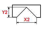
Please indicate the required dimensions in millimeters
X- width of the house
Y- roof height
C- overhang size
B- roof length
Y2- extra height
X2- extra width
Reference
The program is designed to calculate roofing building materials: quantities sheet material(ondulin, nulin, slate or metal tiles), roofing material (glassine, roofing felt), number of sheathing boards and rafters.You can also calculate some useful roof dimensions.
The program works in two modes: a simple gable roof and a roof with two side gables (side roofs), type 1 and type 2.
Attention! If you have a roof with one side gable, then for the calculation use first type 1, then type 2. And from the data obtained, calculate the amount of building materials: rafters, sheathing boards, roofing and sheet materials.
Otherwise there may be an error in the calculation. After all, the program takes into account the cutouts in the main roof for the roofs of the side gables.
In the calculation you will see several numbers: the size or volume of the building material of half the roof and in brackets - the full size or volume.
In the calculation of an additional roof - the full size and volume, and in brackets there are two numbers: the size and volume of one and two additional roofs.
Attention! When calculating sheet roofing material, keep in mind that the program calculates by roof area.
For example, 2.8 rows times 7.7 sheets per row. During actual construction, 3 rows are laid.
To more accurately calculate the number of roofing sheets, you need to reduce the sheet height in the calculation until you get a whole number of rows.
Don't forget to set the amount of overlap more precisely.
When calculating the volume of material for the rafters of the main roof, in mode type 2, the program does not take into account the cutout for the side gable. This is due to some implementation difficulties in the program.
Maybe I'll solve this in the future.
However, the excess rafter material is unlikely to disappear, or make some adjustments to your calculations.
There will also be a separate program for more intelligent calculation of sheet roofing materials.
And don't forget what to buy Construction Materials it is necessary with some reserve for waste.