To repair an iron with your own hands, you need to know how this device is made. Considering the structure of the iron, we can say that it is structurally similar to such devices as a kettle or a heater. The differences lie only in the purpose of the devices and the presence of additional components.
The iron, regardless of the country and manufacturer, has four main components:
- heater;
- plug with cord;
- thermal fuse;
- Temperature regulator.

In order for the iron to start working, voltage must be applied to the tubular heating element located in the sole of the device. Modern models, such as Roventa, use powerful heating elements from 1000 to 2300 W. If you do not interrupt the heating process, the base of the device will become so hot that it will only be suitable for frying scrambled eggs, and not for ironing clothes.
In order to prevent excessive heating, a control device is built into the circuit of the devices. The thermal mode depends on the iron's thermostat, which is selected taking into account the type of fabric: some materials can be ironed at a temperature of 100 C, others require readings of 200 C. In most models, which include Brown irons, the adjustment wheel is located in the upper part of the body under the handle.
An important safety component is the fuse. When the appliance reaches extreme temperatures resulting from a malfunction, the thermal fuse will open its contacts and the iron will turn off.
Before repairing the iron, you need to check the serviceability of the power cord. Most often, it cracks in places of frequent deformation - at the entrance to the case or near the plug. The malfunction may appear gradually when the indicator light flashes during ironing. Such a wink means that there is no normal contact and the terminals may be oxidized.
Another malfunction manifests itself more violently. If the wires rub against each other for a long time, the insulating layer may be damaged and a short circuit may occur. Outwardly, this is manifested by a strong bang, turning off other devices and a specific smell characteristic of burnt wiring.

For women who are especially impressionable, such situations hurt to the core. They perceive the breakdown as a natural disaster and react by calling their husband, the Ministry of Emergency Situations and the house management. The most correct option is the first one, because any man whose hands grow where they should can get the iron to turn on again. Otherwise, you should still contact your stronger half so that he can hand over the item for repair.
The Internet is filled with videos on iron repair. Many stories are devoted to flaws in the supply wire. If the cord is faulty near the plug, there is no need to disassemble the device. In the case where suspicion falls on the part that is hidden by the body, disassembly is indispensable. To carry out, for example, repair of a Philips iron with your own hands, you should remove the back cover. Behind it, the power cord splits into three wires. If the insulation is damaged, it must be restored. If the terminals become oxidized, you need to disconnect the wires and clean the problem areas.
Checking the electric heater
The heating element in modern models is a reliable unit and rarely breaks. When this problem occurs, it is better not to buy a new heater. It's easier to buy a new iron. But first you should make sure that the problem is in the heating element.

In all models, the heater contacts are soldered to the device contacts and connected to an indicator lamp. If the lamp is on, but the iron does not heat up, then the malfunction is related to the heating element.
The most common cause of failure of the heating element is a rupture of the spiral. Another reason may be insufficient contact of the heating element rods with the device terminals at the connection points.
On some models, the thermal fuse is included in one heater circuit, and the regulator is included in another. If the fuse is faulty, then a false “diagnosis” can be made, suspecting a faulty heating element. To accurately determine the cause of the device failure, it should be completely disassembled.
Problems with the thermostat
The temperature control is carried out by a round wheel. It is located in the Azur iron and in other models on the body under the handle. When you turn the wheel to the right, the heating temperature increases, and to the left, it decreases until the heating element is completely turned off.
The wheel acts on the thermostat through a special bushing or steel angle and is attached to the body using latches. In the Scarlet iron and other models, it is enough to pry the adjustment disc with a screwdriver so that it comes off.
The operating principle of the thermostat is based on the various properties of metals. In the manufacture of this unit, two plates made of metals having unequal linear expansion coefficients are soldered together. Thanks to these indicators, the plates each behave differently. Outwardly, it looks like this: under the influence of temperature, the common plate bends, causing the circuit to open, and the iron turns on.
To verify that the temperature regulator is faulty, you will have to completely disassemble the iron.

The handle of the device and the plastic parts of the body are attached to the metal parts with latches or self-tapping screws. Even one manufacturer has many models, and they all have design features. But all species have common points.
To disassemble the iron, you need to examine its sharp part, where there is one attachment point. For example, a Philips iron hides a self-tapping screw under the steam control knob. To unscrew the screw, turn the handle all the way to the left and pull up. After removing the adjusting unit, you can unscrew the screw. In the Brown model, the screw is hidden under the nozzle cover. You can remove the nozzle by slightly pulling it towards you. After its removal, free access to the screw opens. Other screws or latches are located under the back cover of the device.

After the plastic part of the body has been removed, you should consider the iron's thermostat. In cold mode the contacts must be closed. If there is a special device, it is better to ring the node. If you don’t have the device, you can clean the contacts with fine sandpaper and then plug in the iron.
The fuse and other faults are to blame
To fix your iron, you can refer to statistics that say that 50-60% of malfunctions occur due to the fact that the thermal fuse fails. This unit can be disposable or reusable. The fuses of the first group, like a kamikaze, operate only once. The unit is designed so that when the heating element reaches a temperature of 240 C, the circuit breaks. Further operation of the device without additional intervention becomes impossible.

More modern technologies involve the use of bimetallic parts. Such a thermal fuse is capable of turning off the iron in extreme situations, and then turning it on again. If the iron does not work for this reason, the easiest way is to throw away the unit and short-circuit the circuit. This can be done in different ways:
- using soldering;
- by crimping a metal rod;
- switching power wires.
In each case, it is necessary to achieve reliable contact.
Another common problem is a problem with the steam system. Sometimes in a Bosch iron the button that turns on the process is pressed hard, and no steam is supplied. Repairing a Bosch iron should begin by unscrewing the screw at the back and removing the back cover. Then you should carefully pull the two buttons that regulate the steam supply up. They are not secured with screws and are held on the bushings by friction. Next you need to unscrew the screw, after which the plastic handle should come off easily. Under the cover there are two pumps: one supplies water to the sprinkler, the other delivers water to the sole to create steam. The steam pump needs to be removed. There is a ball at the bottom, which sticks to the bottom of the chamber due to scale. To fix the problem, you need to push the ball into the chamber and reassemble the iron in the reverse order.

Whatever iron you have to repair, you need to remember safety and follow certain rules: turn on the device only when necessary; do not try to fix the problem with wet hands; During repairs, the iron must be placed on a stable, non-current and heat-resistant coating.
An iron that fails at the wrong time can ruin all your plans, especially if you are far from hypermarkets and hardware stores. You can try to repair the unit yourself. Not all modern models can be repaired, but there are devices that can be brought back to life. First you need to get to the insides. How to disassemble the Scarlet iron? This, as well as the repair of some other models, will be discussed in our article.
What's happened?
Before you disassemble the Vitek, Scarlet or any other iron, try to figure out what exactly happened. There are different types of problems:
- the iron does not heat up;
- the iron turns off quickly;
- the iron overheats;
- steam comes out;
- steam does not spray out.
In the first case, you must first of all inspect:
- the wire;
- socket;
- fork;
- place where the wire and plug are attached.
Socket and cord
If everything is ok, inspect the outside of the wire:
- There should be no knots, kinks or damage to the insulation on the cord.
- There should be no wire sticking out at the junction of the wire and the plug, and the sheath of the wire should be free of cracks and breaks.
- Do not allow the fork to have cracks or loose screws.

What to do with the cord?
If there is visible damage, it is best to replace the wire; fortunately, in any company store of the company that produced the iron, you will also find components. To do this, of course, you will need to remove it.
But sometimes there is no way to disassemble the iron. Therefore, in the damaged area, you need to connect the broken pieces of wire and wrap it all with electrical tape. Or just wrap it if the outer part is torn. It is quite possible that you will not have to get to the terminal block.
Other damage
If everything is fine with the wire and the electrical network in the house is working normally, most likely the heating element has burned out. When the iron quickly turns off or overheats, there may be problems with both the heating element and the thermostat. These parts cannot be repaired; it is best to replace them.
Important! It is better to buy replacement elements from the same company that produced the unit itself - then there is no risk that the parts will not fit.
What does an iron consist of?
Any electrical appliance consists of many different parts. Modern irons, of course, have fewer small elements than old ones. Individual elements are combined into non-separable units, and it is the group of parts that changes.
Regardless of whether you need to disassemble a Scarlet, Vitek or any other iron, you need to understand what’s inside it. Each iron has:
- sole with built-in heating element;
- water tank;
- thermostat with handle;
- nozzle;
- steam regulator;
- cord;
- fork;
- contact block.
Important! Almost all modern models have holes in the sole. They are designed to release steam. Using a thermostat, the ironing mode is set - it is he who is “responsible” for the temperature to which the sole will heat up. The steam unit includes not only a water tank, but also a sprinkler for the forced release of heated steam, and a supply regulator.

We begin to disassemble the iron
Before disassembling a Vitek or any other iron, prepare the necessary tools and materials. You need:
- Screwdriver Set;
- wide knife;
- multimeter;
- soldering iron;
- solder;
- insulating tape;
- heat shrink tubes;
- sandpaper;
- pliers.
You will need two types of screwdrivers:
- flat;
- crusades;
- with asterisks (rare, but you can find them).
Important! The knife can be successfully replaced with any hard, flat object - for example, a ruler or a bank card that you forgot to throw away. With their help, you will pry off those parts that are attached to the latches.
A multimeter is needed to test the wire and all elements of the electrical circuit that make you suspicious. Sandpaper will come in handy if you need to clean the contacts.

We film what is filmed
Where to start repairing the Scarlet iron? There are not many options - after examining the unit, you will see that there are only a few screws, and besides them, there are removable parts. Therefore, it is better to act in this order:
- Remove the thermostat disc (just pinch it with your fingers and pull it up).
- Remove the steam buttons (in the same way as the disk, and if necessary, press the latches).
- Unscrew the screws on the back cover.
Most of the screws are on the back panel:
- They need to be unscrewed; this is usually not a problem.
- It may very well be that there are additional latches. Use a flat object to pry the cover and remove it from the body.
- Under the cover you will see the terminal block. This is what needs to be checked right away - it is quite possible that the cord has burned out or come loose.
Important! This nuisance can be easily eliminated, and there is no need to further disassemble the Scarlet iron or any other. The burnt wire must be soldered, insulated and ringed with a tester, and then simply screw on the cover.
If the block is ok
If the terminal block is working properly, the iron will have to be disassembled further. It should be taken into account that some models (including Scarlett) may also have fasteners under the cover and on the handle, most often bolts. They also need to be removed. In general, you need to remove all fasteners that are removed.
Important! To keep them from getting lost, place a white sheet of paper on the table and place the screws and bolts on it in the order in which you unscrewed them.
Unscrew the screws until the sole is separated from the body. This is possible for almost all models.
How to ring a block?
For this you need a multimeter:
- Put it in dialing mode.
- Press one probe onto one of the plug contacts.
- With the second probe, touch one wire on the block, and then the other - the device should beep once.
- Repeat the same experiment with another “plug-wire contact” pair. If there is a signal this time, the wire is in perfect order.
Checking the heating element
This is the main part of any heating device.
Important! If the element fails, it is best to buy a new iron - some companies have a very strange marketing policy, when replacing the element is more expensive than a new device.
But first the heating element must be checked. To do this, you need to get close to the sole itself:
- Look at the back of the sole - there should be two outlets for the heating element.
- Measure the resistance with a multimeter; to do this, it must be set to measurement mode up to 1000 Ohms.
- Look at the display - when you see a value of about 250 ohm, leave the heating element alone, it is working properly.
- If you see a value greater than 250 Ohm, run to the service center for a new heating element or to the store for a new iron.
Important! To avoid problems with the heating element, you just need to regularly care for the device. And there is nothing complicated about it. See for yourself by looking at several effective and very simple methods.
If the cause of the breakdown is too serious and purchasing a new part will be very expensive, it is reasonable to purchase a new device. Ours will help you in this matter.

Checking the thermostat
It can be extremely unpleasant if you put the disc on “silk” or “synthetic”, and the unit heats up in a second as if you were going to iron cotton. There's nothing you can do, you'll have to deal with the thermostat.
It is a plate with a pin and many contacts. The pin is needed so that the disk can be put on it - the same one that you removed at the beginning of the process. Then we proceed like this:
- We are looking for two contacts that fit the plate.
- We put multimeter probes on them and ring in two positions,
- If the thermostat is set to the “off” position, there should be no squeaking noise.
- In any other position the device should beep.
There may be several problems:
- If in the “on” position the device does not make sounds, the iron does not heat. This case may turn out to be quite simple - it is possible that carbon deposits have formed. The contacts need to be cleaned with fine sandpaper.
- The regulator behaves the same in all positions. In this case, you can try to separate the burnt contacts, but this is not always possible for everyone. It is best to replace the thermostat.
Important! Sometimes the contacts stick to each other. This happens if the iron falls. The iron heats up - the plate presses on the contacts, but they do not open. In this case, the plates must be forced to move, but bending must not be allowed.
Fuse
This detail can also cause a lot of trouble. It is located approximately in the same place as the thermostat, and is needed to prevent overheating. Typically the fuse is protected by a white tube (but may be of a different color):
- Locate the fuse contacts.
- Set the multimeter to dial mode.
- Check your contacts.
- A squeak is heard if the part is in order.
Important! Theoretically, the fuse can be excluded from the circuit, but this is not necessary. It's better to replace it. You can get out of this situation by soldering a piece of copper wire with a cross-section of 0.5 mm in place of the burnt element and putting a piece of cambric on it.

Steam supply system
Doesn't steam come out even though the tank is full? First, let's check the holes. You can deal with the problem quite quickly by performing simple iron repairs.
Option 1:
- Take a clean frying pan.
- Fill it with water.
- Add vinegar at the rate of 1 tbsp. table vinegar per 1 liter of water.
- Turn off the iron.
- Place it in a frying pan so that the solution covers the entire sole.
Option 2
You can make another solution:
- Pour a glass of boiling water into a frying pan (or other dish with low sides).
- Dissolve 2 teaspoons of citric acid.
- Place the iron in the frying pan.
- Place the entire structure on the stove and bring the solution to a boil.
- Turn off the burner.
- Wait until it all cools down.
- Heat the stove again
- Repeat the procedure until the salts clogging the holes dissolve.
Important! In the same way, you can clean not only the iron, but also the soleplate separately - to do this, the top of it must be sealed with polyethylene and tape, and only then lowered into a container of water.
If water does not come out of the sprinkler
This is a fairly simple breakdown, most often caused by a disconnected tube:
- Disassemble the panel on which the injection buttons are located.
- Put all tubes and wires back in place.

Do-it-yourself repair of the Scarlet iron
The irons of this brand are not much different from other popular modern models, but still have some features. As in all other cases, to work you need:
- screwdrivers;
- flat object;
- nail scissors;
- tester.
Important! The most difficult step will be the first step. Irons of this brand have a decorative cap at the back with an unusually shaped screw. The easiest way to unscrew it is with small scissors, but a screwdriver with a corresponding tip may not be included in the set.
- Open the lid of the hole into which water is poured.
- Remove the screw (a Phillips screwdriver will do).
- Remove the back wall (same as with other iron models).
- Unscrew the remaining screws.
- Remove the thermostat knob.
- Open the unit attached to the sole - there is a heat sink there..
- Check all contacts as described in the previous case.

Iron Vitek
The principle of examining a unit of this brand will be the same as for the Scarlet, but again, there are some subtleties, and the first of them is the screws that secure the back cover. You will see three-pointed stars on the slots, so a Phillips screwdriver will not save you, nor will a star screwdriver.
As you can see, most of the likely problems with household appliances can be fixed with your own hands. But still, if you have no idea about the operation of irons and electrical appliances in general, it is better to contact a service and repair center so as not to aggravate the problem.
However, manufacturers are against unauthorized repairs, and therefore constantly complicate the system so that it is almost impossible for an ordinary person to repair. It is not profitable for all manufacturers to produce eternal things; it is more profitable to constantly purchase necessary household appliances. Still, let's try to study the theory of repairs at home.
Necessary tools
To carry out repairs, we will take care of some tools; they can be done independently without much expense. Here is the list:
- a pair or two of push-ups;
- secret fastener squeezer;
- inexpensive LED flashlight and magnifying glass;
- a long and narrow piece of suede, a nail file, alcohol;
- The last point can be replaced with a slate or ink eraser, or a piece of clean rag; alcohol is required.
Push-up
It is made from the top strong shell of bamboo, its dimensions are approximately equal to the thickness of an ice cream stick, one end is cut into a wedge. Often a non-fixed mount is used; service technicians remove them with special pliers. At home, the lids are pryed off: the latch teeth have a double-sided bevel and leave the grooves without breakage. It is not recommended to remove the cover on tight latches with a table knife or screwdriver, as shown in the figure. Steel deforms the plastic and can render the lid unusable.
Why you need to use bamboo - the bending strength of its top layer is greater than plastic, but the shear strength is less. A bamboo squeezer, if manipulated correctly, will remove the cover; if done incorrectly, it will deform itself, but will not damage the coating. To remove, use a pair of squeezers, prying the lid off both sides.
You can make a squeezer by cutting a plastic coffee stirrer, which is placed in coffee machines, into a wedge. It is thin and suitable even for a thin gap, it will carefully remove the mustaches of the fixed fasteners, will not scratch them and will not break anything inside the device.
Flashlight and magnifying glass
Small, cheap LED flashlights shine harshly, casting harsh shadows. For our repair this is an advantage, since this illumination penetrates even into very small gaps; with the help of a magnifying glass you can see what the part is holding. To carry out this operation, they lift the lid with the problem of dismantling, shine a flashlight there and look through a magnifying glass to see what is holding it in place.
How to remove latches
It is optimal to find a dismantling diagram in the service book, but often they are simply not there. There is no standard disassembly scheme, since each brand comes up with its own secret latches. Moreover, they can vary even in different models of the same TM. The book says in this regard: “The manufacturer reserves the right to make changes to the design that do not affect its performance.” This specifically applies to hidden fasteners; you will have to look for them yourself.
By the way, Western manufacturers are gradually moving away from making structures that, if repaired independently, can only be broken even more. But Asian companies stubbornly follow it. For example, in some Chinese products, the nose locking screw is not located behind the filler cap, but behind the water and steam spray buttons.
We shine and watch. In the picture it is highlighted in green - this is not a latch, but a tenon in a groove. The latch itself is located on the reverse side. To disassemble, remove the buttons:
- press forward button;
- insert a thin squeezer through the back;
- release the latch;
- the clamp is in its original position, we lift the button up as long as it goes, and we will hear a soft click of the tooth, meaning that it has come out of the groove;
- support the button from falling, remove the holder;
- we continue to support, move forward at an angle, turning the tenon out of the groove;
- We repeat all manipulations with the second button.

Shaped fasteners
Fasteners in European models are often used with a regular Phillips screwdriver or hexagon. If you don’t have a suitable hexagon, you don’t need to buy one; you can unscrew such a clamp with a regular flat-head screwdriver with a blade of a suitable size. It is also suitable for screws with a trefoil slot, a favorite of Chinese manufacturers. But you should not clamp the screwdriver too hard, since the side clamp is created significant and the screw can jam in the thread. If the fastener is screwed in very tightly, it is removed with several sharp turns, placing the tool in different pairs of grooves.

Things are worse with the bolt in the picture on the right - a TORXX slot; scissors or tweezers will help here if the fastener is loose in its socket. The easiest way to carry out the operation is with small duckbill pliers or side cutters, but the latter will leave marks on the slot bridge. The fastener itself will not do anything, but the next time you have to contact service, an experienced technician will see that an unqualified person tried to gain access to the inside of the device, and will use this excuse to increase the cost of repairs.
Steam iron device
To make it easier to find all the secret screws, let’s carefully study the structure of the iron with steam supply. Its standard diagram is shown below:

Impact steaming with superheated steam is not installed in all models; it has an effect only if there is a maximum position of the regulator - three points. In expensive models with impact steam, the steam pump is blocked when the regulator pointer is set to lower positions. This is written in the instructions, which few people read. If there is no steam boost, you need to set the regulator to maximum, this may solve the problem.
Innovation in the electronic part - turning off the heating element when changing the position of the sole. When the device is placed vertically on purpose or due to a fall, the heating is turned off by the position protection module. It is this part that ranks second in terms of breakdowns in high-quality models; scale formation comes first, which will be discussed further. Both breakdowns often fall under the category of self-repair.
How the Chinese steam
Having examined the soles of irons from China of different categories, you can see that most models have drip humidification nozzles that are not real. In fact, it turns out that during major heating you can get a burst of steam by holding down the steam button; in the same position of the regulator, soft steam appears from the button with droplets; to get drip humidification, press both at once.
Electrical circuit of the iron
Relay KM and spatial location sensor SK - positional protection. Here you can often find a power indicator, neon, not LED. The protection can be turned off, which will not affect the operation of the iron for the consumer, but the LED indicator will also not work, and this is already inconvenient to use. We disable the protection in parts, maintaining its functionality.
The picture shows numbers with indices - this is the sequence of actions when calling the “hot” and “cold” circuits with a multimeter: one probe with a crocodile is hooked onto the pin with the mains plug, the second is passed through the positions. Both continuities will occur on the contacts of the KM relay. In the normal state, the KM contacts are not closed: if the device is connected to the network, the contacts of the KM thermostat pull, the closed contacts supply current to the heating element. A malfunction of the direct positional protection turns off the heating element according to the principle of redundant safety. For a master without relevant experience, this fact can become a puzzle.
It may happen that when calling back, a lack of contact in the connecting cap is discovered. In such a situation, the only thing that will help is to cut the wires and re-seal them into a new one.

Thermal protection (thermal)
The overheating fuse is activated if the temperature threshold of the sole goes beyond 240 degrees or a current of the specified value passes through the heating element. Select a new fuse according to the current and power of the unit:
- 2200 W - 25 A;
- 1500 W - 16 A;
- 1000 W - 10 A;
- 600 W - 6.3 A.
Thermal protection is selected with a reserve, 220 V is the effective indicator of the voltage in the network, the amplitude is 220 V x 1.4 = 308 V. The half-cycle of the frequency lasts 50 Hz 10 ms, the thermal protection is triggered for 4-5 ms. In a situation where the current jumps to the 245 V threshold, the thermal indicator for the operating current of the heating element in a fully working device may deteriorate.

Fuses are presented in three modifications - one-time, recoverable and self-recoverable. The first one melts in an emergency; in order to avoid damage to other parts, it is placed in a sleeve that is dielectrically resistant to temperatures, most often made of fiberglass. Otherwise, the mains voltage may break through to the sole. In the second case, there is a bimetallic plate with voltage, it clicks and disconnects the contacts. To return everything to working condition, press it through a specially left window and press it with something sharp until it clicks. The third option returns the plate to its original position itself when the equipment cools down. Such thermal heaters are paired with a temperature controller and are always equipped with a current fuse.
Thermostat
The sole temperature regulator is one of the main vital parts and therefore most often breaks down. This is a mechanical trigger device that operates using a bimetallic strip. Neither has anything to do with the temperature controller in the refrigerator. The only similarity is the presence of a trigger, but the design is completely different. It works on this principle:
- The spare part with a moving contact is fixed in a static area by a reversible spring. When the contacts are closed, voltage is applied to the heating element. The spring compression is set using a special knob on the body.
- The reverse side of the contact is combined with a dielectric pusher rod equipped with a bimetallic plate.
- The last part is deformed by heating and acts on the moving contact through the rod; this effect continues until the spring is overpowered.
- The spring throws the contacts and separates them.
- The heating element turns off, the sole reduces the temperature.
- The plate gradually returns to its position when the pressure on the spring decreases, it is thrown back and the regulator returns to the starting position.
The heating element gains temperature, the cycle begins again. In old models and some new ones, the regulator is designed with an unfixed rocker arm - 1 in the figure. 
The structure has significant drawbacks - four burnout contacts and a large temperature fluctuation between operation and the regulator being reset to the starting position. This design is complemented by a calibration screw under the handle; it is tightened when the iron heats up too much or unscrewed if the heat is weak. To remove the calibration screw, remove the temperature control knob. It is friction mounted on an axle and secured in the body with claws on a spacer. To remove it, turn it to the minimum value until it stops and then pull it towards you.
Most models have unified temperature controllers with a double spring system - 2 in the picture. It works with high precision and does not require adjustments. Weak points - as in the case described above, contacts will be discussed below. The ceramic rod marked in blue, in some cases it cracks. Its length is 8 mm; a replacement part is made from an MLT-0.5 W resistor, 2 in the picture. Its leads are cut to 1.5-2 mm, the paint layer is removed with dichloroethane or a surfactant remover, and the conductor layer is removed using sandpaper. When the resistance value is from 620-680 kOhm, it is set so that the paint will burn without smoke or odor. But the sole will pierce and pinch your hand. An even more unpleasant situation is a decrease in resistance if there is an unprotected conductive current on the resistor, and the leakage current will increase by several positions. 
It happens that the washer-insert in the regulator cracks. The replacement is made from fluoroplastic, picture 2b.
Cleaning contacts
Sometimes it is recommended to clean the contacts with sandpaper, but this is not true, a lot of voltage passes through the wires, and cleaning with this method reduces the time before burning. In current models, thin-walled stamped contacts are used; they burn out completely. To clean, take a nail file, wrap it in suede soaked in alcohol, stick it between the contacts and three until no carbon marks remain on the suede. Or cut a narrow wedge from an ink eraser, clean it with it, and then go over it with the same wedge, but from a pencil eraser. At the end of the procedure, we take the same nail file, wrap it in alcohol with a rag and remove the eraser particles with it.
It happens that the iron heats up to its maximum, changing the position of the regulator knob and the calibration screw does not affect the situation. This symptom indicates a soldering of contacts. Only replacement will help.
How to disassemble an iron
Standard disassembly is carried out according to the following scheme:
- dismantle the temperature knob;
- we remove the back cover, sometimes together with the top;
- behind it is a contact block;
- top cover;
- frame;
- temperature regulator housing, if equipped.
Now the inside can be inspected and repaired. Each stage provides nuances during dismantling. Some of them will be considered separately using the example of products from Western companies; now we will describe the general nuances.
Back cover
Only it is fastened with a screw or several. They can be located below in pairs. There are two options here - a single back and top cover or separate ones. The first option provides a straight handle, then the covers are removed by pushing them back with your fingers, fastening is carried out by horizontal axes in longitudinal sockets.
In the case of separate covers, the back cover is secured with one or two screws; here, too, there are two options: a back cover flush with the body or an overlay. If it is flush, then you drag it towards you by the lower part, in its upper part there is a fastening with tenons in the grooves, they will turn out and the lid will come out. The second situation only applies to fastenings with one screw in the middle. If the screw is unscrewed, but the cover does not move or pull, it means that it is secured with double tenons in the grooves - bottom and top. We push it up, release the lower tenons, then pull it down, turning the upper ones out of the grooves.
Block
After dismantling the back cover, a contact block will be revealed; it itself is a source of breakdowns. In models of different prices, it can be the simplest screw; they replace the fused one with propylene. Do not install polyethylene and PVC, as they will not withstand the temperatures.
The most reliable design is with slip-on terminals - 2 in the figure; unscrew 2 screws of the power cord clamp and a couple of screws securing the terminal block directly. We connect the network wires to the sockets of the block related to them; if this does not happen, the block must be replaced or plug-in terminals must be installed on the wires. It will not be possible to rewire the wires into the terminal block.
Top cover
The uneven top-mounted lid is latched but not secured. You can remove it with two squeezers, discussed above, the process starts from the rear edge, if that doesn’t work, we take it from the front.
Positional defense
Most models have a position protection module under the housing. The weak point here is the position sensor. Most often it is a plastic box - indicated by red arrows in the picture; there are always a couple of exits there. The position sensor is securely covered with a lid or covered with a compound on top; it is easily picked off.

It is not difficult to determine the breakdown: the unit does not turn on, but a small chatter will make it work briefly and turn off again. Inside the sensor you can find a couple of contacts and a metal roller in a dense and dirty coating. Initially, it was pure and colorless silicone, but the spark appearing from the relay contributed to the modification. As a result, carbon deposits prevent the roller from making contacts and moving as expected.
Spoiled lubricant is removed with table vinegar; it is not recommended to use the roller without lubricant. During use, the device will heat up randomly, the relay will clap, and the service life of the sensor will be significantly reduced. If there is no silicone, you can use machine oil; this option is even better, since it resists dirt and does not perceive sparks. Before application, wipe the sensor with alcohol, place a syringe needle on the oil can, and carefully apply the oil without staining the walls. After all the manipulations, fix the lid back with any superglue; the fatty walls will not stick together.
Braun and some others send the position sensor signal through a microcircuit where it is processed. In this design, it is better to leave the roller without lubrication.
Another possible malfunction is burnt contacts or a winding on the relay; in such a situation, switching on will not occur at all. To check the module, it is removed and operating voltage of direct or alternating current is applied to the winding; this number is written on the body - a green line. We will hear a click and the tester will detect a short circuit. If this does not happen, the relay needs to be replaced.
If you have doubts about the data written on the relay, measure the resistance. If the winding current at a given voltage is from 80-100mA, do not allow it to pass through the winding. Check the relay from the regulated power supply. Most often the operating voltage is up to 24 V.
Positional defense is not an important element. To fold it back and leave the heating element indication, unsolder the white wire, make a connection to the brown one, or unsolder it and connect the red one. The relay sometimes begins to make clicking and rattling sounds, so we unsolder it too.
Frame
When the back cover and contact block are removed, we will see the tenons fixing the housing in the grooves - at the bottom of the picture. There may be screws there, but we don’t remove them yet, since there may be a couple more screws holding the case in the spout area.
It has already been discussed how the Chinese hide screws; from other manufacturers you need to look for them under the filler cap. When the top cover is removed, the neck will remain in place. To remove the neck, lift the filler flap and remove the cover using a wringer, you will see the screws on the nose - the top part of the picture.

Next, the iron body is dismantled and removed with pumps, we see all the malfunctions leading to a lack of steam, water entering inside, which is why the iron throws sparks, makes noise and breaks. This could be salt deposits in pipes and valves or cracks in pipes. You cannot glue the tubes, as this is ineffective at high temperatures. First, we clean the water supply system from scale. In nipples we do this with a solution of citric acid in a proportion of 1 tsp. per glass. We fold the broken tubes, put on pieces of heat-shrinkable tubing, and heat them with a household hair dryer.
Problems of different brands
Tefal
There are individual nuances. The housing is dismantled with the top cover. The nose screw is under the water dispenser cover (left and center in the picture), it can be seen through the translucent plastic. To access the pumps, remove the top cover on the dismantled housing. The screw is located behind the buttons - the right side of the picture; to remove the cover it is removed.

This brand is a leader in the production of cordless irons. There are three types of products: contacts are located on the platform, the sole accumulates heat, and the cord shoots off. The first and second options can be repaired yourself, the third may falsely appear to be faulty.
The cord is ejected by a pusher operating from a non-system trigger mechanism with an individual bimetallic plate. If it seems that the temperature has already dropped, but the cord cannot be inserted back, it may turn out that the device has simply not cooled down enough. We wait until the temperature drops, try to put it on again, set the regulator to high temperature and wait for shooting. The system is not very convenient, so it is not sold out.
Phillips
A distinctive feature of TM Philips is its double body. The popular Azur model is dismantled according to the standard scheme - And in the picture, the difference in the placement of the back cover latches is a pair of screws in the lower part. Under the decorative layer with pumps we will find an internal protective casing with protection - B in the picture, then there is a massive sole, in fact, the third body, on which there is a thermostat and a thermal thermostat - B in the picture.

They are typical in design and can be disassembled as easily as possible: there is a cover on the back with 1 screw without any tricky fastenings. To dismantle, unscrew the screw and pull back the input hose of the network cord - in the figure, the cover will be removed together with the hinge, then disassembly proceeds as usual.

Brown
The ineradicable sin of these devices is the steam generator tank with thin walls made of galvanized steel and the fastening of the regulator casing with bendable legs made of the same material. It rusts very well, there is no point in repairing it.

Bringing back steam
Expensive and cheap models are susceptible to scale formation. Cleaning it without disassembling the tank is problematic; doing it as shown in the figure is strictly forbidden - the owners boil their iron in a frying pan with vinegar.

Acetic acid will float on the plastic, making it brittle, it will corrode the rough surface of the nickel on the sole, and the Teflon coating will peel off. To carry out proper cleaning, the device is disassembled down to the sole, as in the video.
It was already said above that to remove scale from an iron, it is better to use lemon acid. Before cleaning, the heating element contacts and ceramic bushings are tightly wrapped with high-quality soft insulating tape in 3-4 layers or heat-shrinkable tape.
Scale from the nozzles is cleaned with a toothpick. At the end of the procedure, generously rinse the system with pure water from top to bottom, pouring it into the steam generator tank. Only this procedure will guarantee the service of the iron.
Since then, when people took off animal skins and began to wear woven clothes, the question arose of removing folds and wrinkles from things after washing. Things were pressed down with flat stones, ironed with frying pans filled with hot coals, and everything else housewives could come up with until the American inventor Henry Seely patented an electric iron on June 6, 1882.
And only in 1903, the American entrepreneur Earl Richardson put the invention into practice by producing the first electrically heated iron, which seamstresses really liked.
Operating principle and electrical circuit of the iron
Electrical circuit diagram
If you look at the electrical diagram of a Braun iron, you might think that this is a circuit for an electric heater or electric kettle. And this is not surprising; the electrical circuits of all the listed devices are not much different. The differences lie in the design of these household appliances due to their different purposes.

The 220 V supply voltage is supplied through a flexible heat-resistant cord with a molded plug to the XP connector installed in the iron body. The PE terminal is a grounding terminal, does not take part in the operation and serves to protect a person from electric shock in the event of a breakdown of the insulation on the housing. The PE wire in the cord is usually yellow - green colors.
If the iron is connected to a network without a ground loop, then the PE wire is not used. Terminals L (phase) and N (zero) in the iron are equivalent; which terminal receives zero or phase does not matter.
From terminal L, current is supplied to the Temperature Regulator, and if its contacts are closed, then further to one of the terminals of the heating element. From terminal N, current flows through a thermal fuse to the second terminal of the heating element. A neon light bulb is connected parallel to the heating element terminals through resistor R, which lights up when voltage is applied to the heating element and the iron heats up.
In order for the iron to start heating, it is necessary to apply supply voltage to a tubular electric heater (TEH) pressed into the sole of the iron. To quickly heat the sole, high-power heating elements are used, from 1000 to 2200 W. If such power is constantly supplied, then within a few minutes the sole of the iron will heat up red-hot and it will be impossible to iron things without ruining them. To iron items made of nylon and anide, an iron temperature of 95-110°C is required, and items made of linen require an iron temperature of 210-230°C. Therefore, to set the required temperature when ironing items made from different fabrics, there is a temperature control unit.

The temperature control unit is controlled using a round knob located in the central part under the handle of the iron. When turning the knob clockwise, the heating temperature will increase; when rotating counterclockwise, the heating temperature of the soleplate will be lower.

Rotation from the handle to the thermostat assembly is transmitted through an adapter in the form of a sleeve or a metal angle placed on the threaded rod of the thermostat. The handle on the iron body is held in place by several latches. To remove the handle, just pry it by the edge with a little force using the blade of a screwdriver.
The operation of the thermostat of the Philips iron and any other manufacturer is ensured by installing a bimetallic plate, which is a strip of two metals sintered over the entire surface with different coefficients of linear expansion. When the temperature changes, each metal expands to a different extent and as a result the plate bends.

In the thermostat, the plate is connected through a ceramic rod to a bistable switch. The principle of its operation is based on the fact that, thanks to a flat curved spring, when passing through the equilibrium point, the contacts instantly open or close. Speed of action is necessary to reduce the burning of contacts as a result of the formation of a spark when they open. The switching point of the switch can be changed by rotating the knob on the body of the iron and thus control the heating temperature of the soleplate. When you turn the thermostat switch on and off, a characteristic soft click is heard.
To increase the safety of operating the iron in the event that the thermostat breaks down, for example, the contacts are welded together, modern models (there was no thermal fuse in Soviet irons) install a thermal fuse FUt, designed for an operating temperature of 240°C. When this temperature is exceeded, the thermal fuse breaks the circuit and voltage is no longer supplied to the heating element. In this case, what position the temperature control knob is in does not matter.

There are three types of thermal fuse designs, as in the photo, and they all work on the principle of opening contacts due to bending of the bimetallic plate as a result of heating. In the photo on the left is a thermal fuse for a Philips iron, and at the bottom right is a Braun one. Usually, after the temperature of the sole drops below 240°C, the thermal fuse is restored. It turns out that the thermal fuse works like a thermostat, but maintains a temperature suitable for ironing only linen items.
To indicate the supply voltage to the heating element, a neon lamp HL is connected parallel to its terminals through a current-limiting resistor R. The indicator does not affect the operation of the iron, but allows you to judge its performance. If the light is on, but the iron does not heat up, it means that the heating element winding is broken or there is poor contact at the point where its leads are connected to the circuit.
Wiring diagram
The entire electrical circuit of the iron is mounted on the opposite side of the soleplate, made of high-strength aluminum alloy. This photo shows the wiring diagram of a Philips electric iron. Wiring diagrams of irons from other manufacturers and models of irons differ slightly from those shown in the photo.

The supply voltage of 220 V is supplied from the power cord using plug-in terminals placed on pins 3 and 4. Pin 4 is connected to pin 5 and one of the heating element pins. From pin 3, the supply voltage is supplied to the thermal fuse and then to the iron’s thermostat, and from it via the bus to the second terminal of the heating element. Between pins 1 and 5, a neon light bulb is connected through a current-limiting resistor. Pin 2 is grounding and is riveted directly to the sole of the iron. All current-carrying busbars of the circuit are made of iron, and in this case this is justified, since the heat generated in the busbars is used to heat the iron.
DIY electric iron repair
Attention! Care should be taken when repairing an electric iron. Touching exposed parts of a circuit connected to an electrical outlet may result in electric shock. Don't forget to remove the plug from the socket!
Any home handyman, even one who has no experience in repairing household appliances, can carry out repairs on his own iron. After all, there are few electrical parts in the iron, and you can check them with any indicator or multimeter. It is often more difficult to disassemble an iron than to repair it. Let's look at the disassembly and repair technology using the example of two models from Philips and Braun.
Irons stop working for one of the following reasons, listed by frequency of occurrence: a broken power cord, poor contact of the terminals where the cord is connected to the electrical circuit, oxidation of the contacts in the thermostat, a malfunction of the thermal fuse.
Checking the service cord
Since during ironing the power cord is constantly bent and the greatest bending occurs at the point where the cord enters the body of the iron, the wires in the cord usually fray at this point. This malfunction begins to appear when the iron is still heating up normally, but when ironing, the heating on indicator blinks, without being accompanied by a click of the thermostat switch.
If the insulation of the conductors in the cord frays, a short circuit may occur with an external manifestation in the form of a flash of fire with a loud bang and tripping of the circuit breaker in the panel. In this case, you need to unplug the iron from the socket and begin repairing it yourself. A short circuit in the iron cord is not dangerous for humans, but it is very impressive for housewives.
If the iron stops heating, then first of all you need to check the presence of voltage in the outlet by connecting any other electrical appliance to it, such as a table lamp, or connect the iron to another outlet. Before doing this, do not forget to turn the temperature regulator on the iron clockwise at least to the first circle on the scale. In the extreme left position of the thermostat knob, the iron can be turned off. If the socket is working properly and the iron does not heat up, then with the cord plug inserted into the network, move it at the entrance to the iron body, simultaneously pressing, while observing the power-on indicator. The same operation must be done in the area where the cord enters the power plug. If the indicator lights up even for a moment, it means that there is definitely a wire break in the power cord and you will have to take the iron to a service workshop or repair it yourself.
Using a multimeter or pointer tester
If you have a multimeter or pointer tester, you can check the power cord without connecting it to the network, which is safer by connecting the probes of the device, turned on in resistance measurement mode, to the pins of the power plug. A working iron should have a resistance of about 30 ohms. Even a slight change in the reading of the device when moving the cord will indicate the presence of a broken wire.
If the power cord is frayed at the point where it enters the electrical plug, then there is no need to disassemble the iron, but it will be enough to replace the plug with a new one, cutting it off at the point where the wire is damaged.

If the power cord is frayed at the entrance to the iron or the proposed method does not allow you to determine the faulty cord, you will have to disassemble the iron. Disassembling the iron begins with removing the back cover. Difficulties may arise here due to the lack of a suitable bit for the head of the screws. For example, I don’t have bits for an asterisk slot with a pin in the center, and I unscrew such screws with a flat-head screwdriver with a suitable blade width. After removing the cover from the iron, all the contacts necessary to find the faulty part in the iron will become available. It will be possible, without further disassembling the iron, to check the integrity of the power cord, the serviceability of the heating element and the thermostat.

As you can see in the photo of the Philips iron, three wires come out of the power cord, connected using slip-on terminals to the terminals of the iron in insulation of different colors. The color of the insulation is the marking of the wires.
Although there is no international standard yet, most European and Asian manufacturers of electrical appliances have accepted yellow-green Use the color of the insulation to mark the grounding wire (which is usually denoted in Latin letters P.E.), brown– phase ( L), light blue– neutral wire ( N). The letter designation is usually printed on the iron body next to the corresponding terminal.
Conductor insulation yellow-green color is grounding, serves to ensure safety, and does not affect the operation of the iron. The current-carrying wires are brown And light blue insulation, so they need to be checked.
Using a table lamp
There are many ways to check the power cord of an iron and it all depends on what tools the home technician has at hand. If you don’t have any equipment at hand, then you can use the simplest method.

To do this, you first need to remove the cord plug terminals from the iron terminals. The slip-on terminals on the iron contacts are usually held in place by latches, and in order for them to be easily removed, you need to press the latch with a sharp object, as shown in the photo. At the same time, you need to inspect the contacts for oxidation or burning, and if any are present, clean the contacts from the bottom and top to a shine using fine sandpaper. If the terminals are put on without effort, then you need to tighten them with pliers. Step-by-step instructions for repairing terminal connections in photographs are given in the article “Restoring terminal contact”. After this, you need to put the terminals in place and check the operation of the iron by connecting it to the network. It is quite possible that this was the fault and the iron will work.
If the terminal connections are in order, then you need to remove the terminals attached to the brown and blue wires and connect them to the plug pins of any electrical appliance using insulating tape, a table lamp with an incandescent or LED bulb is best suited for this. The switch in the table lamp must be in the on position. After this, plug in the iron's plug and crumple the iron's wire at the point where it enters the body and at the plug. If the table lamp shines steadily, it means that the iron wire is working properly and you will have to further look for the fault.
Using a phase indicator
Checking a tubular electric heater (TEH)
Heating elements in irons rarely fail, and if the heating element is faulty, then the iron has to be thrown away. To check the heating element, it is enough to remove only the back cover from it. Typically, the terminals of the heating element are connected to the outer terminals and, as a rule, the terminals of the heating on indicator are connected to the same terminals. Therefore, if the indicator lights up but there is no heating, then the reason for this may be a break in the heating element’s spiral or poor contact at the points where the iron leads are welded to the contact rods coming out of the heating element.

There are models of irons, such as the Braun model shown in the photograph, in which the thermostat is connected to the break of one terminal of the heating element, and the thermal fuse is connected to the break of the other. In this case, if the thermal fuse is faulty, then an erroneous conclusion can be made that the heating element is faulty. The final conclusion about the condition of the heating element can only be made after complete disassembly of the iron.

Checking the serviceability of the iron thermostat
In order to get to the thermostat to check, you need to completely disassemble the iron. The handle of the iron and the plastic part of the body are attached to its metal part using screws and latches. There are a huge number of models of irons, even from one manufacturer, and each of them has its own mounting methods, but there are general rules.

One attachment point is usually located near the nose of the iron and the plastic body is fixed with a self-tapping screw, as in this photo of a Philips iron. In this model, the self-tapping screw is located under the steam quantity adjustment knob. To get to the head of the screw, you need to turn the handle counterclockwise until it stops and pull it up. After removing the steam supply adjustment unit, the screw can be unscrewed.

In the Braun iron model that I had to repair, the self-tapping screw was hidden under the decorative cap of the water nozzle. To unscrew the screw, I had to remove the nozzle. It just fit tightly. By the way, it can be removed for cleaning if it becomes clogged.

The second attachment point is usually located in the area where the power cord enters. The plastic body of the iron can be attached either with self-tapping screws or with latches. The Philips iron model shown in the photo uses a threaded mounting method. From the point of view of the repairability of the iron, fastening with self-tapping screws is preferable, since during disassembly the risk of damage to the fastening elements of the plastic case is reduced.

And in the Braun iron model, the plastic part of the body with the handle is secured using two latches hooked onto the eyes. To disassemble, you need to disengage the latches by moving them apart.

This work must be done carefully so as not to break the latches and eyes. The latches are disengaged, and now the body part with the handle can be separated from the iron. It, in turn, is attached to the adapter cover with screws or using flags.

In this photo of a Philips iron, the cover is secured to the soleplate using three screws. Before unscrewing the screws, you need to remove the power indicator, which is held in place using slip-on terminals on the iron's terminals.

And on the Braun iron model, the lid is secured to the sole using four metal flags threaded through slots and turned. To release the cover, use pliers to turn the flags so that they align with the slots. In this iron, two flags at the spout were completely rusted, and I had to bend a special adapter from a steel strip and cut two threads in it for screw fastening.
After removing the cover, the thermostat assembly will become accessible for testing and repair. First of all, you need to inspect the condition of the contacts. The Philips iron also has a thermal fuse in the thermostat assembly. When cold, the contacts must be closed.

If the appearance of the contacts does not cause suspicion, then you need to ring them using a dial tester or multimeter turned on in the minimum resistance measurement mode. The photo on the left shows the continuity diagram of the thermal fuse contacts, and on the right - the thermostat. The multimeter should show zero reading. If the multimeter shows 1, and the dial tester shows infinity, it means that the fault lies in the contacts; they are oxidized and require cleaning.
Checking the contacts of the thermostat assembly can also be checked using an indicator to find the phase according to the method of checking the power cord described above, touching one and the other contacts in succession. If the indicator lights up when you touch one contact and not the other, it means the contacts are oxidized.
You can do without checking by immediately cleaning the contacts of the thermostat and thermal fuse with sandpaper. Then turn on the iron, it should work.
If you don’t have any instruments at hand to check the contacts, you can plug in the iron and use a screwdriver blade with a well-insulated plastic handle to short-circuit the contacts. If the indicator lights up and the iron starts to heat up, it means the contacts are burnt. Extreme caution should not be forgotten.

To clean the contacts, you need to insert a narrow strip of fine sandpaper between the contacts and pull it a dozen times. Next, turn the strip 180° and clean the second contact of the contact pair. It is useful to clean the contacts of the thermostat to extend the life of the iron if, for example, when repairing the steam supply system, the iron had to be disassembled.
Examples of self-repair of irons
Recently I had to repair two faulty irons from the Braun and Philips brands. I will describe the problems that had to be fixed.
Braun electric iron repair
The iron did not heat up, the indicator did not shine in any position of the thermostat adjustment knob. When bending the power cord, there were no signs of the iron working.

After removing the back cover, it was discovered that the supply voltage was supplied through the terminal block. Access to the plug-in terminals was difficult. The wire markings corresponded to the generally accepted color markings. The iron had already been repaired previously, as evidenced by the broken left latch on the terminal block.

The appearance of the removed terminal block is shown in the photograph. It also has a neon light indicating the supply of supply voltage to the heating element.

The input contact busbars for supplying supply voltage were in some places covered with an oxide film of rust. This could not cause the iron to break down, which was confirmed by connecting it after removing traces of rust from the contacts using sandpaper.

After completely disassembling the iron, the thermal fuse and thermostat contacts were tested using a multimeter. The thermal fuse shows a resistance of zero ohms, and the thermostat contacts show infinity.

Inspection showed that the contacts were tightly adjacent to each other, and it became obvious that the reason for the failure lay in the oxidation of their surfaces. After cleaning the contacts with sandpaper, contact was restored. The iron began to heat up normally.
Philips electric iron repair
I received a Philips iron for repair after the owner cleaned the steam generation system. The thermostat did not work, and the iron heated up to the temperature at which the thermal fuse opened.

After completely disassembling the iron, it was discovered that the ceramic pusher, which should be located between the bimetallic plate and the thermostat switch, was missing. As a result, the bimetallic plate bent, but its movement was not transmitted to the switch, so the contacts were constantly closed.

There was no old iron from which the pusher could be removed, there was no opportunity to buy a new one, and I had to think about what to make it from. But before making the pusher with your own hands, you needed to determine its length. The bimetallic plate and the switch had coaxial holes with a diameter of 2 mm, in which the standard pusher was previously fixed. To determine the length of the pusher, take an M2 screw and two nuts. To secure the screw instead of the pusher, I had to lift the thermostat by unscrewing one screw.
Attention! The bimetallic plate is in contact with the soleplate of the iron and has good electrical contact with it. The switch plate is connected to the electrical network. The screw is metal and is a good conductor of electric current. Therefore, touching the soleplate of the iron when making the described adjustment must be done only with the iron plug removed from the socket!

The screw was inserted into the hole of the bimetallic plate from below, as in the photo, and secured with a nut. Thanks to the ability to rotate the second nut clockwise or counterclockwise, it became possible to adjust the height of the pusher simulator in order to configure the thermostat to maintain the temperature set by the temperature control knob.
The length of the pusher at which the heating temperature of the iron corresponds to the one set by the position of the adjustment knob can be selected by doing test ironing. But for this you will have to assemble and disassemble the iron every time. It is much easier to use an electronic thermometer. Many multimeters have the function of measuring temperature using a remote thermocouple.

To measure the temperature of the soleplate, you need to put the handle on the thermostat and set it to the position with the mark one, two or three circles opposite the pointer on the iron body. Next, attach the thermocouple to the soleplate of the iron, fix the soleplate in a vertical position and turn on the iron. When the temperature of the sole stops changing, take readings.
As a result of the experiment, it was determined that a pusher with a length of about 8 mm was required. Since the iron inside the body can heat up to a temperature of 240°C, the pusher had to be made of heat-resistant material. A resistor caught my eye and I remembered that in it a resistive layer is applied to a ceramic tube. The 0.25 W resistor is just the right size, and its shortened copper leads, threaded through the holes, will serve well as clamps.

The resistor will fit any value. Before installing it in the iron, the resistor was heated to red on a gas water heater burner and the burnt layer of paint and resistor coating were removed using sandpaper. Everything was removed down to the ceramics. If you use a resistor with a value of more than 1 MOhm, which you need to be 100% sure of, then you don’t have to remove the paint and the resistive layer.

After preparation, the resistor was installed instead of the spacer ceramic element and the ends of the taps were slightly bent to the sides. The iron was assembled and the operation of the thermostat was rechecked, which confirmed that the temperature was maintained by the thermostat within the limits of the data given in the table.
What is the maximum temperature that a Philips iron can reach?
When calibrating the thermostat, I decided to find out at the same time what the maximum temperature an electric iron can heat up to is.

To do this, the terminals of the thermostat and thermal fuse were short-circuited. As you can see in the photo, the device showed 328°C. When the soleplate was heated to this temperature, the iron had to be turned off for fear that its plastic part might be damaged.
I love puzzles... especially unexpected ones. This unexpected puzzle “fell on my head” today. More precisely, it fell not on my head, but on my shirt, and it didn’t fall, but fell off.
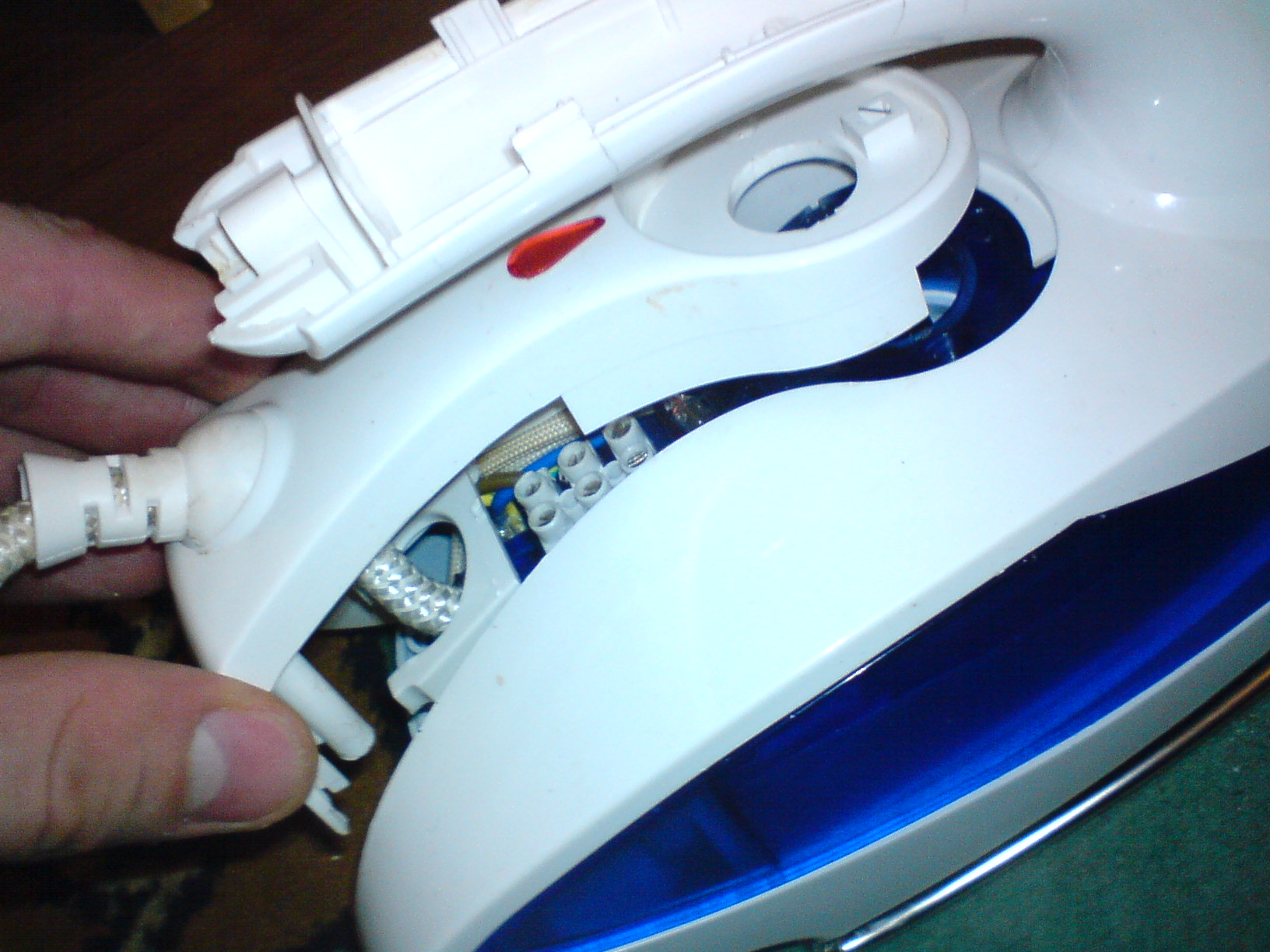
The iron fell apart in my hands while ironing a shirt... I took it just like that and the sole fell off (it remained hanging on the wires). The problem turned out to be one unscrewed screw (the flimsiness of fastening the soleplate of the iron aroused my suspicions from the very beginning), which secured the soleplate to the “nose” of the iron.
In order to screw this screw into place, it was necessary to disassemble the entire iron, which was a puzzle. A quick Google search did not bring a solution and I had to “assault” the iron... So I decided to combine solving the puzzle with a photo shoot. Maybe it will be useful to someone, although the model of the iron is not known... but still..
This is what my iron looked like at the very beginning, with the soles falling off and the top of the iron assembled:

The heel of the sole is attached without screws, with some kind of grip-anchors)) That is. the reliability of the design rests on the same screw on the nose of the iron.

Let me note that I took the photographs after disassembling the iron... so what follows will be a “reconstruction of events.”
So meet the iron itself:

Disassembly should begin with the sneaky hidden screw under the lid of the water tank:

But you need to remove the cover from its closed state by hooking it with a screwdriver and lifting it up.
Unscrew the first screw:


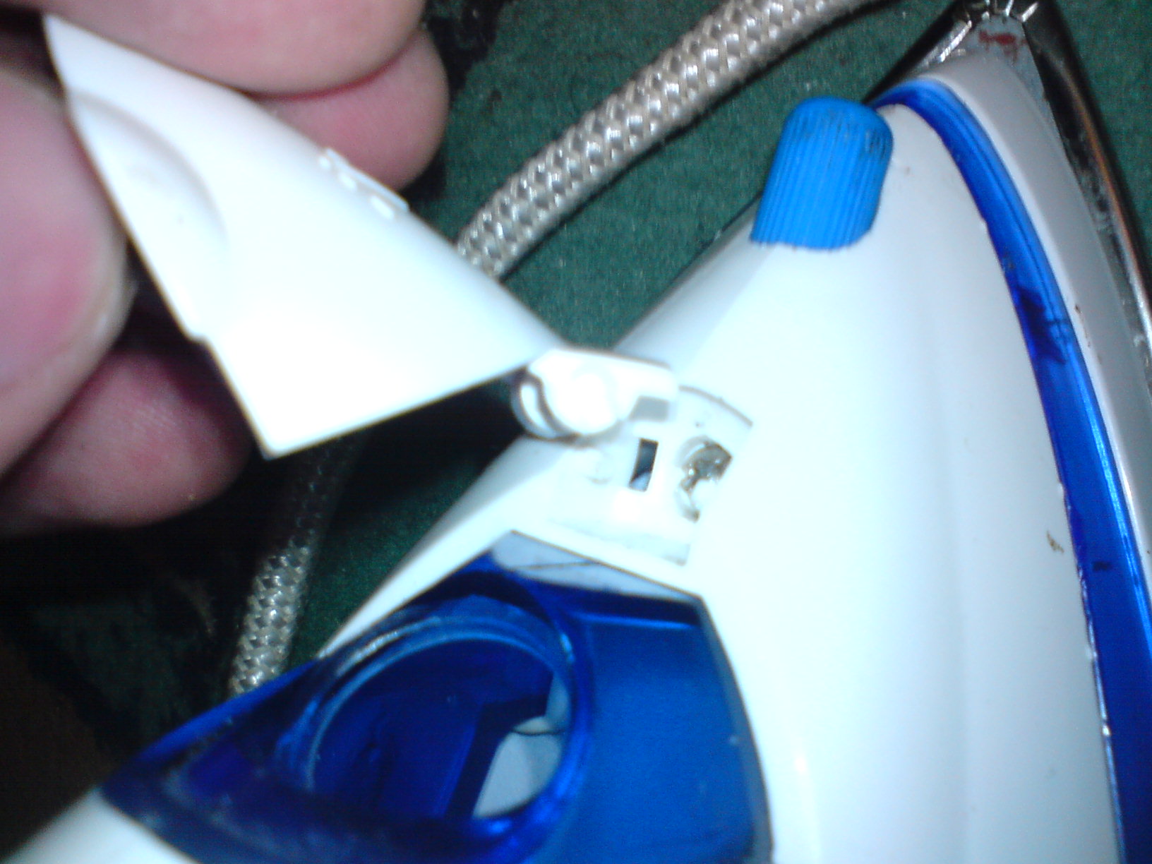
We take out the “horned stuff” from the end of the handle and take out the rotary regulator. To do this, unscrew it counterclockwise until it stops, and then pull it up.

We unscrew this screw, this is the second hidden screw. I found it only when I was assembling the iron... did I break it or was it broken before me (the iron is not mine) will remain a mystery!!! In my case, there is an option to buy super glue or find dichloroethane and glue the plastic together:


The next 2 screws are hidden under the temperature control cover. It will have to be brutally torn out with a screwdriver. (in my case it was easier, I pushed it out from the inside, because the sole was not screwed on yet)

Unscrew the screws here and near the heel of the sole. There will be 4 more screws: two large and two smaller...

Let's remove the detail:


Mesh filters on the bottom of the cylinders...
You also need to be careful not to tear off (as I did) the tube leading to the sprayer on the nose of the iron:

ALL, I finally got access to the ill-fated screw on the nose of the sole. It can be screwed and assembled iron. But I recommend checking the integrity and tightness of all contacts. And in general, carry out maintenance on the iron, it’s already been disassembled...
When assembling, do not forget to put various little things in place so that there are no “extra parts” left after the repair:

two crap things that I almost forgot to put on. These are some kind of gaskets...
That's it, I tighten the ill-fated screw:

And I begin assembly... in the reverse order of disassembly....
The only thing I will note is that in order to correctly assemble the temperature regulator, I unscrewed it all the way clockwise and accordingly knew in what position the regulator cover itself should be put on... this was the position of the maximum temperature:

Look like that's it…. don’t forget about the screws and don’t get nervous when assembling and disassembling))))
This entry was posted on October 5, 2008 at 13:47 and is filed under with tags . You can follow any responses to this entry through the feed. You can, or from your own site.