Very cool and useful thing. Bearing puller. A pipe, an iron plate, a large washer, a bolt, and a nut will come in handy.
First, mark on the pipe the size that needs to be cut. Weld a washer to the resulting segment. Place the nut evenly on the hole and weld it. Let's clean the uneven areas with a grinder.
Measure 1.5 centimeters and make a cut. On the other hand it's the same. Cut two small pieces from the plate. They will be inserted into two slots. The result is a puller.
How does this tool work? We put it on the bearing. We go behind him for two records. Rotate the bolt. It rests on the shaft and pulls the bearing off it. Using this device, you can easily remove it from the generator and electric motor. Outside diameter details should not exceed inner size pipes.
Video AVTO CLASS.
Second idea
Ayrat Valiakhmetov, the host of the youtube channel of the same name, has developed his own original idea. In the store, such tools are not cheap. So I decided to do it myself. I took a metal strip 30 mm wide and 4 mm thick. I cut it into strips. Cooked. Plates. Hooks to grip the bearing. Two cuts are made with a grinder. Two nuts are inserted and welded. I took the worm from an old Soviet clamp. Hardened steel. To make the tool universal, I made 4 holes on each side. Can be installed at any width. If necessary, the paws are pulled out and turned over to the other side. You can pull out the bearing.
When repairing electric motors, in addition to open-end wrenches and a set of heads, you must also have in your arsenal several pullers for tightening bearings.
One universal one simply won’t do. If you have electric motors from 1 kW to 100 kW on your site, then you need to have 2-3.
I have two bearing pullers in my arsenal. There are now on the markets big choice pullers, and you can purchase them. But if there is material, lathe, gas and electric welding and desire, then you can make a puller with your own hands. And I assure you, it will serve you for decades.
You should definitely use three-jaw pullers: they are the most convenient. I will also indicate the dimensions of my pullers, which have long been tested during repairs. Let's start with a small one, with which you can remove bearings from sizes 202 to 308, large - 317 and more. We will need sheet metal 10 mm thick and
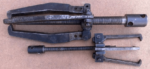
metal round timber with a diameter of 30 mm (for a large one - metal 15 mm and round timber with a diameter of 50 mm).
First of all, we make a drawing (pattern) of the puller legs. We make the length of the legs 200 mm (at the end of the article in PDF format I will post patterns of the legs of the small and large pullers). Next, we apply a drawing on the sheet metal according to the pattern. You need to cut the legs with a gas cutter (propane and oxygen). After cutting, we process the blanks using coarse sandpaper.
Gradually we bring the sizes of the three legs to the same size. There is no need to achieve too ideal dimensions; a difference of 1 mm will not play a negative role in the design. When the legs are made and adjusted, we drill two holes in the upper part (for small expansion possibilities) with a diameter for bolts of 8 or 10 mm (for a large one 12 or 14 mm 3 holes) for attaching the foot to the core of the puller. We do the same with the two remaining legs. We drill holes in them along the first leg, using it as a template. Here we must try to prevent the discrepancy in size from allowing the capture of the bearing to be removed to occur simultaneously. Here's a short description of how to make puller legs.

The next detail is the core. For the core for a small puller, we will need round metal with a diameter of 30 mm and a length of 35 mm (for a large one, 50x45 mm, respectively). In the workpiece, we drill a hole for a 16 mm thread (for a large puller, there is a hole in its workpiece with a diameter of 30 mm) and cut the thread, preferably with a fine pitch. In the prepared part for the core we apply markings, three marks at 120 degrees. And to these places we electric weld two to the marks of the paw holder (the distance between the holders should be as thick as the paw). I think there is no need to describe in detail how to prepare them, since adhere to some strict rules and no sizes needed. After welding, we process this part using coarse sandpaper. Now, having tried on the paw, we drill holes in the holders. The holes must be drilled at a distance from the center, so that the installed foot has good movement to the side to capture larger bearings.
And the third part of our puller is the screw. For the first puller we make it 350 mm long, the thread length is 280 mm, for the second - 500 mm long, for the thread 420 mm. Next, we process the workpieces on a lathe and cut the threads. In the upper part of the screw, where there is no thread, we drill through holes with a slight offset in height and perpendicular to each other. These are holes for mounting or a knob. Diameter is at your discretion. The beginning of the screw can be narrowed in diameter by a small distance. I don't describe the details. Everything can be seen in the photographs.
We made these pullers with a mechanic over 12 years ago. All these years I have had no problems with removing bearings and coupling halves. And most importantly, the quality turned out to be from Soviet times. Like this necessary tool you can easily do it yourself.
When carrying out repairs to the chassis and steering, there is almost always a need to remove ball joints or tie rod ends.
The special feature of these structural elements is that the support finger or tip has a conical shape, with which it fits into the seat.
During operation, the fit density increases so much that the surfaces of this joint practically stick to each other.
Additionally, moisture can get between the finger and the socket, causing pockets of corrosion that further seal the connection.
Therefore, to remove ball joints or tips, special pullers are used that allow you to press out the pin with minimal effort.
Types of pullers
The auto tools market offers wide choose such removable mechanisms, which can be divided into two types:
- Screw;
- Lever.
Screw pullers are considered universal and are suitable for working with almost any car.
The force in them is created by screwing the bolt into the puller body. The housing itself is put on the support eye, and when tightened, the bolt rests against the support pin and presses it out of the socket.
Lever removable mechanisms are no less effective, but they are larger in size, so they may not be suitable for every car.
For example, with such a puller on a VAZ-2107 you can still remove the upper ball joint, but you won’t be able to get to the lower one due to very limited space.
For these purposes, a special puller is used.

The essence of a lever puller comes down to the presence of two levers connected in the middle.
On the one hand, holes are made in them and a coupling bolt is installed.

To press out, one lever is installed between the eye and the support, while the second lever is placed under the finger.
When the bolt is unscrewed, due to the existing connecting axis, the ends of the levers begin to converge and the pin is pushed out.

But it is not necessary to purchase a removable mechanism; it can easily be made at home from improvised materials.
Puller type - WEDGE
The simplest puller is the so-called “wedge”. It does not belong to any type of removable mechanisms, but it is quite effective device for pressing out.
To make it, you only need an angle grinder (“grinder”), you can also use a machine with an abrasive wheel.
The blank will be a metal plate the size of a matchbox.
First, it is necessary to give the workpiece a wedge shape, for which we grind the metal with a grinder or machine so that the profile of the plate looks like a triangle. Then, using the same “grinder”, we make a cut in the middle 2/3 of the length of the workpiece from the side of the apex of the triangle, that is, from the thin side of the wedge. The width of the cut should be slightly larger than the thickness of the support pin, that is, you should get a kind of bracket.

If desired, you can weld a metal rod to the bracket, which will make it easier to work with the wedge in the future.
Pressing out a finger with a wedge is very simple. It is installed in the gap between the eye and the support body. And then the wedge is simply driven in with a hammer, which leads to the finger popping out of the socket.
The disadvantage of the wedge is that the boot will be damaged during the pressing process. Therefore, the wedge can only be used when replacing supports or tips.
If the suspension and steering mechanism are being repaired, which does not involve replacing the ball elements, it is better not to use a wedge.
Screw release mechanism
The second type of removable mechanism, which can be made from improvised means, is a screw release mechanism. It is great for replacing ball joints classic models VAZ.
A special feature of the suspension design of these cars is that the upper and lower supports are located symmetrically to each other and the distance between them is not large.
It can be made at home only if you have drilling machine Or you will have to contact a turning workshop. This puller consists of only two parts.
To make it, you will need a square or hexagonal rod with 17 or 19 key edges, the length of which is 7 cm. Using a drilling machine, we make a hole in this rod and cut a thread for a bolt of 8. Screw in the bolt and that’s it - the puller is ready.

Let's look at how it works using the VAZ-2107 as an example. To press out the upper support, you need to unscrew the lock nut, but not completely, you do not need to remove it. Then we install the manufactured puller between the pins of the supports with the bolt screwed in until it stops.
To squeeze out the finger, we take two keys - with one we hold the manufactured body, and with the second we unscrew the bolt until the finger falls off the socket. After replacing the upper support, we do the same, but with the lower one.
Screw L-shaped
The third type of removable mechanism, which you can make yourself, is also a screw mechanism, but it has shown itself to be excellent and allows you to work on any car.
To make it you will need a round metal rod with a diameter of at least 10 mm and a length of 15-17 cm.
From it you need to make an L-shaped blank with a shoulder length of 5 cm. That is, we take a rod, measure 5 cm on it, clamp it in a vice and use a hammer to bend it 90 degrees.
We cut a thread on the long part of the workpiece and select a nut.
All that remains is to make the thrust bar. It can be made in the likeness of the wedge described above. That is, we take a plate, but 0.5 cm thick. On one side we make a cut for the support pin.
If necessary, you can reduce the thickness of the plate on the cut side by grinding off the metal layer. The main thing is that the plate fits into the gap between the support body and the eye, but it is not too thin, otherwise it will bend during the pressing process.
On the other hand, from the cut we make a hole for the L-shaped workpiece. All that remains is to put the plate on the long part of the rod. If the thread is not long enough to squeeze out the finger, you can place several washers under the nut.

This puller works like this: Unscrew the nut almost completely, install the plate in the gap between the support and the eye, and turn the rod so that the short arm rests against the finger.
Then we simply tighten the nut, while the plate will act as a stop, and the short arm of the rod will squeeze out the finger.


Screw made from angle
Another screw puller can be made from metal corner and welding machine.
To do this, take a corner with sides 7-8 cm and the same length, and a thickness of 0.3-0.5 cm.
We make a cut in one of the sides to secure the mechanism to the eye. From sheet metal 0.3 cm thick, cut out two triangles that will act as braces. They need to be welded on the sides to the corner. This will significantly increase the strength of the structure.
We take a 17 nut and a long bolt for it. We weld the nut itself perpendicular to the cut so that its hole faces the cut.
So that in the future the bolt can be easily positioned on the same axis with the pin, before securing the nut by welding, a spacer must first be welded onto the corner.
All that remains is to screw in the bolt and the puller can be used.


These are the simplest types of removable mechanisms that you can make yourself.
In general, there are a lot of options, and with a little imagination and basic knowledge plumbing, you can easily come up with and make your own puller.
We offer some drawings for viewing.


Tool for unscrewing the support
We will consider another type, which is used not for pressing out the finger, but for removing the support itself.
The fact is that on a number of cars (Peugeot, Citroen) the ball joint is screwed into the lever. With time threaded connection turns sour, and it is quite difficult to unscrew this suspension element without a special tool.
But you can make the necessary puller yourself, rather than spending money on a factory one.
It is made from a thick-walled pipe 2\’\’ 8-9 cm long.

At the end of this pipe it is necessary to make 4 spikes with a width of 5 mm and a height of 7 mm, located at an angle of 90 degrees relative to each other.

That is, you should get 4 protrusions at the end of the pipe, evenly distributed around the circumference. This can be done using a hacksaw and a file, or with a grinder.
An element such as a bearing is used in many components and mechanisms. It can also be found in a car. For example, this or a hub element. In any case, a puller is needed to dismantle it. The bearing is seated very tightly. It is extremely difficult to remove it using improvised means. Therefore, today we will look at what types of bearing pullers there are, their sizes and design features.
Device
The main element in the design of this element is the central bolt. This is what makes the puller work. The bearing is thus squeezed out of the working place or, conversely, pressed in (depending on which direction the central bolt is turned). Some devices are equipped with a hydraulic cylinder (for example, bearings, as in the photo below).
The design also includes grips. They come in two varieties:
- Grips that engage with the object being removed using a special tool. They operate independently of the bolt action.
- Pressing the part due to the force of the bolt or
Material from which the puller is made
The bearing is a part that is quite difficult to remove. Therefore, puller manufacturers use only high-strength alloy materials. The critical nodes in these elements are formed by forging. As for power bolts, they have higher strength than those used in conventional threaded connections.
Kinds
There are several types of these tools. They all differ in the type of grip. He can be:
- Sliding.
- Rotary.
- Conical.
- With separator.
- Universal.
In terms of size, the inner bearing puller can have different diameters. On average - from 28 to 200 millimeters. The height of the foot is from 35 to 60 millimeters. The bolt head size is from 9 to 22 millimeters.
Sliding puller
It is quite easy to remove the bearing with this tool. This puller has two grips that move freely along the beam. In the middle of the latter there is a threaded hole. In the upper part, the bolts can serve as clamps for the grips.

This can be a puller for internal or external bearings. To change its purpose, just rearrange the grips. By the way, their maximum solution ranges from 10 to 80 centimeters. The device has stops for the power bolt. This prevents the bearing from moving. Sliding puller set includes grips different lengths. The tool is also equipped with replaceable tips. Usually they have same sizes(serve as a replacement in case of failure of the first element).
With swivel grips
They have different designs. The grips are locked using bolts. For what vehicles is this bearing puller used? VAZ, MAZ, GAZ, Mercedes - this is an incomplete list of cars on which this tool can be used.

The puller has stops with double-sided grip. There are also three-sided tools. There are 4 mounting points on the body of the device. The paws of the bearing puller are installed on them. The working width of the device is from 5 to 7 centimeters. Used for removing small bearings, including for removing the tip of battery cables. Can be equipped with a striking mechanism.
With conical jaw lock
These tools have 3 jaws and are used in situations where it is necessary to eliminate load asymmetry when dismantling a bearing. This type of hydraulic bearing puller is often sold.

Centering of the grips occurs automatically. The design also has a conical nut, which is manually tightened when installing the tool. On some models it is spring loaded. Has a limited range of uses. It is no longer possible to turn the clamps over here.
With separator
These tools are highly reliable. The element is based on a separator. It is installed under the bearing being removed. Both halves of the cage are bolted together for a more secure grip. After this, the pulling part will be connected to the tool.

Its side nuts are adjustable in accordance with the position of the separator. The power bolt is inserted onto the axis of the part being removed. The tool can be used in combination with a sliding puller. However, when working with two mechanisms, it is necessary to ensure the safety of the bolt threads.
Universal
Universal bearing pullers are most often used. They also extract other mechanisms. The design is based on a power bolt made of alloy steel. By rotating it, the master creates a dismantling force that is applied to the support point. Through the central body of the tool, this force is transmitted to the clamps. Thus, the part is pulled out or pressed into place. Universal pullers are used for both internal and external bearings.
Price
The cost may vary depending on the type, as well as the set of tools included in the package.

The cheapest are two- and three-jaw sliding pullers mechanical type. Their price ranges from 500 to 1 thousand rubles. Hydraulic devices- the most expensive. They are offered on the market at a price of 25 thousand rubles. Cost of universal mechanical solutions is around 10 thousand rubles. The kit includes a set of mandrels.
Options
To choose the right bearing puller, you need to know what parameters it must meet. When purchasing, you should pay attention to the following points:
- Maximum permissible load. This parameter is determined by the strength of the central body of the puller and the power bolt. U mechanical tools this parameter ranges from 1 to 4 tons. Hydraulic pullers have a force of about 20 tons (but they also have a corresponding price). However, to dismantle elements such as the wheel bearing, mechanical tools are sufficient.
- Working progress. It depends on the reach of the power bolt and the length of the grips.
- Dimensions of the puller legs (in particular, the width and height of the stop).
- Minimum and maximum gripper opening.
DIY primitive puller
You can also make this tool yourself. Used as the main element steel pipe. Its diameter should be slightly larger than that of the clip. So, using a grinder, we cut a piece of pipe to the required length. It depends on the size of the screw. Next, using welding, we connect the C-shaped washer to the cut out part of the pipe. On the other side, a nut is welded with internal thread. It must match the parameters of your screw. This type puller is the easiest to manufacture. However, it will only fit a specific bearing diameter.
Making a universal tool
Such a puller will fit different diameters of elements. So, we need to make the legs from a 10mm sheet of steel. It is better to use pre-prepared templates. They can be made on cardboard or paper, then marked on metal sheet and cut with a grinder.

Then you need to select a bolt. We sharpen it to a cone. Six ears with holes are welded to the nut. Our paws will be attached to the latter. The ears are cut out of metal 5 millimeters thick. The ears are welded to the nut in assembled form. Next, the bolts are unscrewed and the connections of the legs are finally welded. At this stage, the assembly of the device is completed. You can begin to fully use the tool.
Conclusion
So, we found out what types of bearing pullers there are. The most common types are universal mechanical solutions. They can be used to remove any bearings and pulleys. A puller is a very useful thing in the household. Especially if you own a car. With this tool you can even perform such a complex operation as replacing a wheel bearing. In the services, the cost of this service starts from 3 thousand rubles.
A must have for every true master. Sometimes there is a need to repair power tools, and specifically to replace bearings that sooner or later wear out. If you remove the bearing using a hammer, screwdrivers, etc. suitable solutions, there is a risk of damaging the axle, threads or individual components on the axle, and this often happens. And sometimes the bearing sits on the axle so firmly that it can be removed far away and not with every puller.
In this instruction you will learn how to make a simple, powerful puller that will always help you out in difficult situation. To assemble it you will need a piece of thick-walled pipe and a thick steel plate. If you wish, you can make yourself several pieces of these pullers for products of various sizes. Let's consider in order how to make such a device.
Materials and tools used
List of materials:
- thick-walled pipe;
- thick steel plate;
- bolt and nut (larger);
- metal rod(a handle is made from it);
- dye.
List of tools:
- ;
- (cutting disc, metal brush, and grinding disc);
- drill with bits big size or drilling machine;
- lathe, cutting machine(not necessary).
Puller manufacturing process:
Step one. Preparing the main part
The main part of the puller is a piece of thick-walled steel pipe; it acts as a frame. If the pipe is not strong enough and the loads are large. It can easily bend. The thickness of the pipe walls must be at least 3 mm.


We cut off the required piece from the pipe; the author uses a cutting machine for this, but everything can be done with a grinder. Now comes the hard part, you need to cut a window in the pipe. This can be done using a grinder; it takes a long time, but is quite doable.
Step two. We make the upper and lower supports
For the upper support, the author decided to use the thickest sheet steel possible. Cutting out a circle required diameter. The author uses a grinder for work, first we cut out the “polygon”, and then using a grinding wheel we bring it to perfection.
Cut out the other circle in the same way. Here the author used slightly thinner steel, but it’s better not to risk this, since the loads on both supports are approximately the same.


Finally, you need to finalize the supports. You need to drill a hole in the top support for the bolt. First we drill a small hole with a drill, and then drill it out to the desired diameter. The author used a lathe for these purposes.
As for the lower support, we also drill a hole in the center; its diameter should be slightly larger than the diameter of the axles from which you are thinking of removing the bearings. Then cut out a triangle shape for this hole. The supports are ready, let's move on!


Step three. Welding work
In this step we need to weld both supports to the body. The welding seam must be good and reliable; we set a higher current so that the metal melts well.


Having welded the supports, you now need to secure the nut. We wrap the bolt in it and insert it into the hole. We weld the nut well, but try not to overheat, as the metal may become soft. The author attaches the nut from above, but I would recommend fastening it from the inside, so it will rest on the support, and the tensile weld may not be very reliable.
Finally, all you have to do is secure the handle; for this, the author used a threaded rod. Using a handle will make it convenient to remove bearings that are not too rigid. Otherwise you can always use wrench.


Step four. Completion and testing
When you're done welding work, needs to be cleaned welds, but this is more a matter of aesthetics; there is little practical benefit here. The author cleans off the slag with a wire brush and cleans the seams grinding disc. The entire body can be polished. Now paint the homemade product so that the metal does not rust.


Finally, sharpen the end of the bolt so that it rests when screwed into the “hole” provided on any axis. Also, be sure to lubricate the threads well so that the puller will work easily and for a long time.