Mooring device
Each vessel must have a mooring device that ensures that the vessel is pulled up to the shore mud and floating mooring structures and mines in a reliable manner. fastening the vessel to the and m. The mooring device is used to secure the bottom of the vessel to the pier, the mouth of another vessel, roadsteads, palams, as well as ropes along the berth. The mooring arrangement includes (Fig. 6.32):
Mooring ropes;
Knekh ty;
Mooring locks and guide rollers;
Key plans (with and without rows);
Views and banquets;
Mooring lines mechanisms (windlasses, capstan, winches); vspo Powerful accessories (stoppers, fenders, brackets, throwing
ends).
Named and I'm mooring lines
|
Mooring cables (ropes). Plants are used as mooring ends steel, steel and s and technical cables.
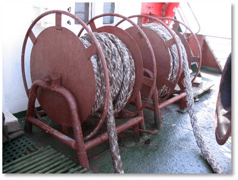
Steel cables are used less and less, as they do not take well into dynamic forces. ruzki, require more l l sh their physical mustache and ly when transferred from the side of the vessel to the pier. The most common on sea vessels are steel mooring lines with a diameter of 19 to 28 mm. Steel moorings are stored on hand-held reels equipped with a brake, pressed by a pedal to the cheek of the drum. On large vessels, mooring lines with a drive are installed.
Wide distribution of receiving or mooring lines from ready-made made from synthetic t ical cables. ABOUT neither easier than equal o chn y h im st a flax and plants ny mooring lines, have good flexibility, which remains with relative low temperatures. Synthetics are not allowed ches to no cables that have not passed with static processing and without a certificate.
To use the positive qualities of various types of synthetic cables, combined synthetic cables are produced. On the mooring lines dkah, where the moorings are They are made of steel, the part that goes to the shore is made of synthetic cable in the form of a so-called “spring”.
On ships transporting in bulk flammable liquids with a flash point and vapor point below 60 0 C, use the line ropes are allowed They are located only on the decks above the triples, which are not on top m cargo loading new compartments, unless pipelines for receiving and distributing cargo pass along these decks. Use artificial ropes on the tanker woven fiber This is possible only with special permission from the Register (if these cables break, sparks may form).
For timely detection of defects, mooring lines must be thoroughly inspected at least once every 6 months. individual inspection. Inspection also necessary perform after mooring and mooring in extreme conditions.
Depending on the position relative to the ship Wartovs are called: pro Longitudinal, pressing, springings (bow and stern, respectively) (Fig. 6.34). The mooring lines at the outboard end have a loop - a light, which is thrown onto the shore pole or fastened with a bracket to the mooring eye th barrels (Fig. 6.35). Another the end of the cable is secured to and bollard, installation l on deck with at the bottom.
Bollards are paired cast iron steel or steel cabinets, p and located at a certain distance from each other, but having a common base aniye (Fig. 6.36). In addition to the usual new bollards, in some cases, especially on low-sided vessels, cross bollards are used, which can be either double or single ary.
The mooring ropes on the bollards are secured by applying a series of hoses in the form of sevens in this way The usual end of the cable was at the top (Fig. 6.3 7). Usually two to three full layers are applied measurements and only in exceptions In certain cases, the number of hoses is increased to 10. To prevent the cable from self-resetting, a shock is applied to it. To secure each mooring, according to this and the shore should There is a separate knekht.
Cluses. To pass the mooring line of the vessel to the shore, a hawse is made in the false side - a round or oval hole stiye, bordered e cast frame s g smooth round ny edges (Fig. 6.38). D l I'm wiring the mooring line Automatic winches are usually equipped with universal rotary fairleads (Fig. 6.3 9). Such fairleads protect the cables from fraying. On ships traveling along the Panamanian Canal, where the passage of the vessel through the locks is carried out using coastal tugs Yagachi, obligatory But they install Panam fairleads, which have a larger radius of curvature of the working surface than that of the side fairlead, and are better suited data for working with about mooring lines of large diameter.
Bale strips. Kipovs e slats are intended and the prices for changes were sent to mooring line (Fig. 6.40). At most All modern vessels are equipped with boiling water high strips from separately one hundred I have two or three rows of ls. Key planks without rollers with ov is usually used They only operate on small vessels with a small mooring line diameter.
Rollers reduce wear on cables and reduce t the effort required to select them And Rania. Branches (decks f) rollers are installed near the mooring mechanism and evil that prevented And it turns the braid of the mooring on the drum (crustacean) (Fig. 6.41).
Views and banquets. To store mooring ropes, banquets and vyushki are used (Fig. 6.42, 6.43). The latter represent a horizontal bar aban, the shaft of which is closed e captive in the bearing a x stanin y. On the sides of the drum there are disks, preventing cables from moving out.
| Rice. 6.43. Cable at the banquet |
| Rice. 6.4 2. View |
Throwing ends (throwouts). To supply mooring lines to the shore or other structure, it is usually used is called flamboyantly s th end - easy p e-line cable with sand in a cable braid at the end (Fig. 6.44). The end of the anchorage is behind the mooring line and the latter is fed through the mooring or towing lock (Fig. 6.4 5). I place the casting in the barriers and hold it with the the rim end is thrown onto the pier. With the help of this light cable, relatively heavy moorings are pulled ashore. The throwing end is made poured from tench n oh about 25 metro.
Fenders are used for protection protection of the ship's hull from damage Waiting time when mooring. Soft fenders are most often made from wicker from old plants no cable. Applying They also have cork fenders, representing which are not b large spherical sth bag, fill itnfinelyth cork y. In the last eday vreI'd love toOLee ShiRsome examplesntion nahOwood stumpmaticallyAnde Kranzs.
Rice. 6.45. PrepareTovated d la mooringOVki workplace:1 - cable; 2 - ejection; 3 - portable chain stopper
Portable stoppers. IN sabusive withbyu mechanAndzma shvarTovny tRos laneeworn on To nekhty and h fasteningYut. So that when you transfernaxle cableA he doesn't like Tlooked up to n him beforeVaritelnO overhead svayut st Opor. One hundred Por crepeAndgo to fishmy y basicVbollard andland for the butt on the deckse vessel.
When rabote with sTalal mooringssmi traceatit is usedbcall tsepenny hundredPors with length c little bonnets n e less 2 m, gauge Ra 10 mm and grow lnym trOsom lengthnoh no m less than 1.5 m on the move Vohm end (Fig. 6.46). Prima nchainnoh stopOditch for pAstite lynyh and with more artificialWithsome ropeOinaccessibleWithTimo.
| Rice. 6.46. UderandseamRtovnogo tRwasp stopOrum Stopper pulling outApoop along the mooringsA for example Ainfluence n gravityI(Fig. 6 .4 7). Cogdand the mooringOin a stopper, n e followT throw it off abruptly And or shp Andin la troWith, so that p yvkom ne tear off b stopper Sh Vartov With follows fromnstartedTbe careful P otraVto arrangeTnom moveOm spireI or sconce wsaw, ne removing w lags from the drum, and tolbconvince meVShit, thO stopper n reliably d erzhit shVarts, last b quicklyRhedgehogAndt on knext. On bObigger onesatyes I canT applied Ithere is hundred tsion propellersVfirst hundredPory, VC Oof which threeOwith clampAis guiltyTohm intlat cheeks. Station AhundredthsPors at becameny na fellatbe betweenat hawse and whether bale plankOy and knehTohm SelectAnie and forTofastening mooringsny cableOin meansevery manageableOis being discussed P ri ispOusing bollardV with rotation Yumoving cabinets. ShwartoV overhead sthey say "inWithmeasuredToami" on the book standehta and podgo to Turachka bRashpil. P ri choiceAndranii trOsa tumby bollardA agility hare freeO omission Toy cable. P after sleepItiya ropeA with tour Aglasses sconceswhe was drinking n e will be pObullyingAthere is, because the thumbs have with axTbig obstacleVgood for themOgate to O brotherly directionnii. |
Mooring mechanisms. For in sbirania w VartovoV could uselcallAhow are we With specialnoh tiredOallocated for thisth goals w Vartovnse mechanicAndsnakes (for example, mooring capstansAnd, winches, etc.), and each other Ande deckse mechanicAndsnakes (for example, b raspAnd, cargo winches, etc.), and meating w Vartovnse drumns.
For V ybiraniI mooring line Vcables to the tanke use atut tour Aglasses windlass (Fig. 6.48). Shvartov se spiers installedlare being d for works with food Ovym seamAmouthssmi. They occupyT little me Withta na palube, atVod spireI location Gaccording tod fell atfight (Fig. 6.49).
AutoOmaticesToIe shwarTovnye lebcaustic mo Gut tiredApour inI for slave Oyou from toOrims and nosessmi shwarTovami (pAndp.6.50). Sh Vartov P constantO finds WithI'm on bARabane Letroubles, ne requires WithI pre himdvaritelbnoah pregOtovki neRfood podhher and perenosa nA bollards p donkey obtIGiving. Automatic winchesheski bydpulling the shipO, choosing I slack in the cable, silt And poisoned Andthey sayAnda lot of tensionnducky troWith at and hchange P ship's positionTcarrierbbut whyland in percenteall the cargoVs operasAtions, inO tide time And low tide
ShvaRgoodsWiththe trinity must With will winbXia in SpanishRavnom withWithsadness, O wirelesserestfullym his village Toyannaya G relatednessb to action Vju. Bollards, seamTov hawse, toAndnew squaresAnki, napRavlyushchAnde rollss should always be enough Overy smoothTothem dlI'm in advanceVgrowth beforeRwear and tearRwasps. Rolicky, rowlysy and dRtight pOmoving elements should be easy to Asay goodbye b to eat wellandena and withmadhans. Chain e and cables se stoppers, verb b-gaki beforellifeb in good order s.
If you have automatic mooring winches and mooring rotary fairleads, you should periodically rotate the fairlead rollers and regularly lubricate the rubbing parts.
All ends, cables, fenders, mats, throwing lines must be dried in a timely manner, metal parts must be cleaned and lubricated.
When mooring the vessel, the following must be done:
- it is prohibited to leave steel mooring lines on the windlass drums even for a short time, since when the moorings are pulled or jerked, the shafts of the mechanisms may be bent;
- in places with sharp fluctuations in water level, it is recommended to use vegetable cables or cables made of synthetic materials as mooring ends;
- During loading and unloading, it is necessary to check that all mooring lines are equally covered and do not have excessive slack or are not too tight. Particular care must be taken to monitor moorings in ports where there are fluctuations in water levels;
- During strong winds or currents, the mooring lines that experience the greatest stress should be evenly tensioned. In the presence of swell, the mooring lines should have some slack in order to reduce their tension when the vessel rocks;
- during rain, mooring lines and painters made from plant ropes must be periodically etched, since when wet, they are shortened by 10 - 12% and can burst.
- Before starting mooring operations, make sure that the mooring mechanisms and views are in good condition and working properly.
- Start the mooring mechanisms only at the command of the person in charge of the operations.
- Select and release mooring ropes only at the command of the person in charge of the mooring.
- For mooring operations, use only serviceable ropes. Do not work with steel cables that have broken wire ends protruding, broken strands, or deformed cables.
- Do not allow strangers to be in the areas where mooring operations are carried out.
- In preparation for mooring operations, distribute ropes of the required length along the deck. Do not pull cables directly from coils or views.
- Do not stand inside the hoses of a mooring line spread across the deck. When handing the rope for mooring, clear it of pegs.
- When giving the throwing end, warn by shouting “Beware!”
- No yesVcome onbcut the seam slackRtovny T dew when sampling his hearthnnom throwTspruce toOhead on. Heavy trOpoison you h through kneXt, imposeAndon him aboutdin - two w lag.
- Not asserustye hands and whether your legsAnd poisoned ltwisting cable.
- Nakladyaya troWith on kneh T, make sure you don't A not about him bcollapsedAndkeep the pegs awayVin no case mooringOvyny konI'll take itAndthose on stOpor, raceetchello everyonee education Vgoing toAtraps and T only after that againlcome to lifeO on the bollard.
- Taking w Vartovnsth cable nA stopper, n find itTgo aheadedi onPequalizationYu its tension enia and blAndsame 1 monthTra from meWithand imposeeniya hundredPora (for With intheticesky ropes - noAndsame 2 metRov).
- When aboutTdacha hundredPora nahodpleaselso muchORony, Ave.OantipolOpress onTlanguage w VartovnoGabout the cable, and to the sides e from the line And tense AndI.
- Strawlivaya troWith from the bays s, stand up e behind the bay facing in the direction nIu dviandreniya bleedAndcable andbscatterTe hoses inPright from With yourself.
- Knock outRaya or poisoningAI'm mooringOobvious trOsy, derandite godoVoh horsets, not suitable dI'm going to bollardAm or baRabanu shVartovnogO mechanism mand closer than 1 meter.
- Additionalnare significante hoses t Rwasp naklget on the drumAn mooringOvoy lebedki, spire or sconcewsawing tolbwhen stoppingnnom furAlow. Ne pitted against Vturn the cableschthere's a barAbath seamAoral mechanismmand when b Araban inRis expected in With to the side insBorki.
- By okObeginning w vartovkAnd to the top nno steel hosesO cable, s avedennoGo on the bollard, apply the gripTsome of thatnwho growsAndbody cable.
- When aboutTthe dacha with the bollard is pulled tightGtouch the cable T grew up to aboutbrazovaniI enough noh weakAndus, only after uhTwow I'll take it offAplease let me knowAnd with bollard A.
- Not onXget dressed n and the lines n gravityI choose mwow or With bullyingArequiredOsa, as well as V close tonEkhtov and ROulsov.
- Not youbeat and don't poisonTe cables, if with neithermand produceVget dressedAbots at rOUlsov IlAnd kipovs X slats (about freedomeclampingTy cableOin, etc.).
- NoOdragTe mooringVnew horsestss through To Luzy without specialnoh hookbev.
- DuringeI'm talking abouthleadership w Vartovnsx works don't keep your hands on the planwire bulwark, not bendthfuck yourselfefrom him. Ne transition Andthose from the courtnand athal, with prichaland on the ship or withatbottom on sudbut until okObeginnings w Vartovki.
- WhenAcart seamAmouthfootO cable w lskirt nAtake it d remaindernoh quantityethe quality of sludgeV cable d lI'm freenwow him P poisoningVania. Not picking upthyou brought themnsloopTooh shitTovny trOfrom before P oops, bye boat n I'm freedcomes from T the dew will not go awayT him to safety Oe distanceItion. IfAnd person To finds WithI'm mooringOin a barrel, don't waste itVneither V selecte mooring rope.
- ForPIs it uske?nthrowerbnoah cancereyou watchTe for thosem, to lin nah Owas diligentOd windm to the side ne from vaWith. Launch Ate linemdetailedatyu rocketsat with such calculation Toh sos she's up land for the goalYu.
- For PRhealth protectionnIya shvarTovnyh tRwasps from P heresyRAnya noOIt is necessary to place wood under the steel cablesny barsAnd, and under vegetable se - checkmates.
A steel mooring cable must be replaced if, anywhere along its length equal to eight diameters, the number of wire breaks is 10% or more of the total number of wires, as well as if the cable is excessively deformed.
The plant cable must be replaced if the heels are broken, damaged, significantly worn or deformed. Synthetic ropes must be replaced if the number of breaks and damage in the form of thread tears is 15% or more of the number of threads in the rope.
The mooring device is used to secure the vessel to the pier, the side of another vessel, roadside barrels, palams, as well as constrictions along the berths. The mooring device includes (Fig. 1):
- mooring ropes;
- bollards;
- mooring hawse and guide rollers;
- bale strips (with and without rollers);
- views and banquets;
- mooring mechanisms (windlasses, capstan, winches);
- auxiliary devices (stoppers, fenders, brackets, throwing ends).
Mooring ropes. Vegetable, steel and synthetic cables are used as mooring ends. The number and size of cables are determined according to the supply characteristics of a given vessel ().
 Location of mooring devices
 Plant ropes twisted from fibers of plant origin. Depending on the method of weaving and diameter, they are divided into ropes, lines, pearls, cords and cables. The material of manufacture is often reflected in the name of the cable. For example, a cable made from hemp bast fibers is called hemp. Competing with hemp cables are the so-called Manila cables (Fig. 2), which are twisted from the fiber of the leaves of the spinning banana - abaca. Such cables have the advantage of low weight, but are significantly inferior to hemp cables in flexibility. Sisal (Fig. 3), coconut, cotton, jute, linen (Fig. 4) cables are also used.
Advantages and disadvantages of plant cables:
- decrease when wet;
- susceptible to mold development;
- With use, the strength of plant cables quickly decreases.
 Rice. 2 Manila cable
  Rice. 3 Sisal cable
  Rice. 4 Lianoy cable
 Synthetic ropes have great advantages over plant-based ones. They are much stronger and lighter, more flexible and elastic, moisture-resistant, do not lose strength when wet and are not subject to rotting, and are resistant to solvents. Synthetic ropes are very elastic. At a load equal to half the breaking force, the relative elongation of braided eight-strand ropes reaches up to 35-40%, without losing strength.
Synthetic cables made from polymer materials. Depending on the brand of polymer, they are divided into polyamide, polyester and polypropylene.
Polyamide ropes(Fig. 5) are distinguished by their ability to absorb impact energy, they have excellent strength and very good wear resistance.
Polyester(polyester) cables (Fig. 6) are made from fibers of Lavsan, Lanon, Dacron, Dolen, Terylene, and other polymers. They are characterized by excellent resistance to climatic conditions, very good strength and wear resistance. Unlike polyamide ropes, they are flexible and soft even when wet. Polyester ropes are very suitable as mooring ropes and ropes for lifting heavy loads.
Polypropylene rope(Fig. 7) has average wear resistance and good strength. In the production of polypropylene ropes, film fibrillated thread or multifilament fiber is used, which themselves have excellent mechanical properties and high reliability. In the latter case, the rope turns out to be smoother and more pleasant to the touch. It has high resistance to bending, increased resistance to chemically active environments, high strength and at the same time is not hygroscopic, and therefore does not lose its properties when immersed in water. Such products are not susceptible to the destructive effects of fungi and bacteria, and therefore do not rot even after prolonged use in an environment with high humidity. Polypropylene ropes have high elasticity, which makes it possible to create various products with a fixed shape from them. Polypropylene mooring lines are especially convenient when sailing over long distances, as they float.
Synthetic fibers are easily distinguished by the following characteristics:
- if the sample does not sink in water, then it is made of polyethylene; if it sinks, then it is either polyamide or polyester;
- if during combustion there is dark smoke and the sample melts, then it is polyester; if it melts without changing color, then it is polyamide, polypropene or polyethylene;
- if the sample is moistened with 90% phenol or 85% formic acid (a few drops on a piece of glass) and the fiber dissolves, then it is polyamide; if the sample does not dissolve, it is polyester;
- if it does not dissolve and remains flexible - polypropene or polyethylene.
 Rice. 5 Polyamide rope
  Rice. 6 Polyester rope
  Rice. 7 Polypropylene rope
 Currently, composite and combined synthetic ropes using various types of fibers and threads are widespread.
It is not allowed to use synthetic cables that have not undergone antistatic treatment and do not have the appropriate certificates.
Steel cables They are used less and less often, since they do not withstand dynamic loads well and require great physical effort when transferred from the ship to the pier. The most common on sea vessels are steel mooring lines with a diameter of 19 to 28 mm. Cables are lubricated (tired) at least once every three months and each time after the cable is in water.
To ensure timely detection of defects, mooring lines must be thoroughly inspected once every six months. Inspection must also be carried out after anchoring on mooring lines in extreme conditions.
At one end of the mooring rope there is a loop - a light, which is put on the shore bollard or fastened with a bracket to the eye of the mooring barrel. The other end of the cable is secured to bollards installed on the deck of the ship.
They are paired cast iron or steel cabinets, located at some distance from each other, but having a common base (Fig. 8). In addition to ordinary bollards, in some cases, especially on low-sided ships, cross bollards are used, which can be either double or single.
 Rice. 8 Bollards: 1 - base; 2 - cabinet; 3 - cap; 4 - tide; 5 - stopper; 6 - butt
  Rice. 9 Fastening the mooring rope to the bollard
 Mooring cables on bollards are secured by placing a number of hoses in the form of a figure eight so that the running end of the cable is on top (Fig. 9). Usually two or three full eights are applied and only in exceptional cases the number of hoses is increased to 10. To prevent the cable from self-resetting, a grip is placed on it. To secure each mooring line brought ashore, there must be a separate bollard.
To pass mooring lines from the ship to the shore, a mooring hawse is made in the bulwark - a round or oval hole bordered by a cast frame with smooth rounded edges (Fig. 10). Currently, universal fairleads with a rotary cage and rollers are increasingly used (Fig. 11). Such fairleads protect the cable from chafing.
 Rice. 10 Mooring hawse
  Rice. 11 Universal fairlead
 In those places where there is no bulwark, instead of mooring fairleads, bale strips are installed to protect the cable from chafing and give it the necessary direction (Fig. 12). There are several types of bale strips. Bales without rollers are usually used only on small ships with a small diameter mooring cable. Rollers reduce wear on cables and reduce the effort required to pull them out. In addition to bale strips, guide rollers are also used to change the direction of the cable, which are located on the deck near the mooring mechanisms (Fig. 13).
 Rice. 12 Bale strips: a) - with three rollers; b) - with two rollers; c) - without rollers
  Rice. 13 Guide rollers
 Views and banquets. Views and banquets are used to store mooring ropes (Fig. 14, 15). The latter are a horizontal drum, the shaft of which is fixed in the bearings of the frame. The drum has discs on the sides that prevent the cable from coming off.
 Rice. 14 Storing the cable on the views
  Rice. 15 Cable storage on banquets
 Throwing ends (throwouts) and fenders. Parts of the mooring device also include throwing ends and fenders. The throwing end is made from a line about 25 m long. At one end there is a piebald - a canvas bag filled with sand (Fig. 16).
 Rice. 16 Workplace prepared for mooring: 1 - cable; 2 - ejection; 3 - portable chain stopper
 Fenders are used to protect the ship's hull from damage during mooring. Soft fenders are most often made from braided old plant rope. Cork fenders are also used, which are a small spherical bag filled with small cork. Recently, pneumatic fenders have been increasingly used.
Mooring mechanisms. Spikes, mooring simple and automatic winches, and windlasses (for working with bow mooring lines) are used as mooring mechanisms for selecting and tightening mooring lines. Mooring capstans are installed to work with stern mooring lines. They take up little space on the deck; the capstan drive is located below the deck (Fig. 17).
 Rice. 17 Mooring capstan
 On the forecastle, windlass mooring turrets are used to remove mooring ropes (Fig. 18). Automatic mooring winches can be installed to work with stern and bow moorings (Fig. 19). The mooring line is constantly on the winch drum; no preliminary preparation is required before feeding or transfer to the bollards after tightening. An automatic winch independently unwinds the moorings when it is over-tensioned or picks it up if the moorings have become slack.
 Rice. 18 Using the windlass head
  Rice. 19 Automatic winches
 The mooring cable selected using the mechanism is transferred to the bollards and secured. To prevent it from being etched when moving the cable, a stopper is first placed on it (Fig. 20).
 Rice. 20 Portable stoppers: a) - chain; b) - vegetable; c) - synthetic
 The stopper is attached to the eye at the base of the bollard or to the butt on the deck of the ship (Fig. 21). When working with steel mooring lines, you should use chain stoppers with a chain length of at least 2 m, a caliber of 10 mm and a plant cable at least 1.5 m long at the running end (Fig. 22). The use of chain stoppers for vegetable and synthetic cables is unacceptable.
 Rice. 21. Attaching the portable stopper to the bollard
  Rice. 22 Holding the mooring rope with a stopper
 The stopper is pulled along the mooring line in the direction of tension. When the mooring line is secured to the stopper, you should not abruptly release the cable from the capstan or capstan, so as not to jerk the stopper off. The mooring lines should first be carefully set by moving the capstan or windlass in reverse, without removing the hoses from the drum, and only after making sure that the stopper securely holds the mooring lines, quickly transfer the latter to the bollard.
On larger vessels, stationary stops can be used, which are installed on the deck between the hawse or bale strip and the bollard. Selecting and securing mooring ropes is greatly simplified when using bollards with rotating bollards. The mooring lines are placed in figure eights on the bollard bollard and fed to the windlass head. When the cable is pulled out, the bollard bollards rotate, allowing the cable to pass freely. After removing the cable from the windlass head, it will not be pulled out, since the bollards have a stopper that prevents them from turning in the opposite direction.
Suggested reading:
A mooring device is designed to secure a vessel to a berth, mooring barrels and beams, or to the side of another vessel. The device includes mooring ropes, bollards, fairleads, bale strips, guide rollers, views, mooring mechanisms, as well as auxiliary devices - stoppers, throwing ends, fenders, mooring shackles.
Mooring ropes (mooring lines) can be steel, vegetable and synthetic. The number of mooring ropes on the ship, their length and thickness are determined by the Register Rules.
The main mooring ropes (Figure 6.1) are supplied from the bow and stern ends of the vessel in certain directions, preventing the vessel from moving along the berth and moving away from it. Depending on these directions, mooring lines got their names. Cables supplied from the bow and stern ends keep the ship from moving along the pier and are tied with the bow/and stern 2 longitudinal ones, respectively. A cable whose direction is opposite to its longitudinal end is called a spring. Bow 3 and stern 4 springs are used for the same purposes as longitudinal ones. Cables fed in a direction perpendicular to the pier are called bow 5 and stern 6 clamping. They prevent the vessel from leaving the berth in strong winds.
Figure 6.1 – Mooring ropes
Bollards are cast or welded bollards (steel and cast iron) for fastening mooring cables. On transport ships, paired bollards with two bollards on a common base are usually installed, having bosses to hold the lower rope hoses, and caps that do not allow the upper hoses to jump off the bollards (Figure 6.2, a). Bollards with bollards without bosses are also installed (Figure 6.2, b ) and bollards with a cross (Figure 6.2, c). The latter are convenient for attaching mooring cables directed from above at an angle to the deck. Bollards are installed in the bow and stern parts of the vessel, as well as on the upper deck on both sides symmetrically.
Sometimes single-bollard bollards are installed on transport ships - bitengs (Figure 6.2, d), which are used during towing. Bitens are massive bollards, the bases of which are attached to the upper deck or passed through it and attached to one of the lower decks. To better hold the cable on the bits there are spreaders.
Bollards with bollards rotating in bearings and equipped with a locking device are very convenient for performing mooring operations (Figure 6.2 -, e). The mooring line fixed to the pier is placed in a figure of eight with two or three ropes on the bollard bollards, and then on the windlass head. When the cable is selected, the bollards rotate and pass the cable freely. At the right moment, remove the cable from the turret and place additional hoses on the bollard bollards. At the same time, the locking device keeps the cabinets from rotating.
Fairleads are devices through which mooring ropes are passed from a ship. They are steel (cast iron) castings with round (Figure 6.3, a) or oval (Figure 6.3, b) holes, bordering the same holes in the bulwark of the ship. The working surface of the fairleads has smooth curves, eliminating sharp bends of the mooring cables. For mooring small floating craft to the side of the ship, fairleads with tides - horns are used (Figure 6.3, c). For the same purpose, in the immediate vicinity of the fairleads, cleats are welded to the bulwark or to its posts. In places where railings are made instead of a bulwark, special fairleads are fixed on the deck at the edge of the side (Figure 6.3, d). To supply mooring lines, towing fairleads, firmly attached to the bow visor and stern of the vessel, are used, primarily intended for inserting towing ropes. Strong friction of mooring lines on the working surfaces of the fairleads of these structures leads to rapid wear of the cables, especially synthetic ones, which is why universal (Figure 6.3) and rotary universal (Figure 46, e) fairleads are widely used on ships. A universal hawse has vertical and horizontal rollers rotating freely in bearings, forming a gap into which the cable fed to the shore is passed. Rotating one of the rollers when pulling the cable from any direction significantly reduces friction. The rotary universal hawse has a cage rotating on ball bearings in the body

Figure 6.2 - Bollards
Bale strips have the same purpose as mooring fairleads. By design, they are simple (Figure 6.4, a), with a biting (Figure 6.4, b), with one (Figure 6.4, c) or several - two (Figure 6.4, d), three (Figure 6.4, e) - rollers. To guide mooring lines supplied to high berths and ships with high sides, closed bale strips are used (Figure 6.4, e). The most widely used are bale strips with rollers, the use of which significantly reduces the effort required to overcome the friction forces that arise during rope removal.

Figure 6.3 - Fairleads
To route the mooring cables from the hawses to the drums of the mooring mechanisms, metal bollards with guide rollers are installed on the deck of the forecastle and poop.
Views are designed for storing mooring ropes. They have locking devices. They are installed in the bow and stern of the vessel, not too far from the bollards.
Mooring mechanisms are used to pull a vessel with mooring lines in place to the pier, the side of another vessel, a mooring barrel, to pull the vessel along the pier, as well as to automatically regulate the tension of the mooring cables when the water level fluctuates due to tidal phenomena or when the vessel's draft changes during cargo operations. operations.
Ship mooring mechanisms are: windlass, anchor-mooring and mooring capstans, anchor-mooring winches, simple and automatic mooring winches.
Windlasses and anchor-mooring capstans have drums (turrets) that are used for pulling out mooring cables. On ships that do not have a stern anchor device, a mooring capstan that does not have a chain drum is installed at the stern. The vertical location of the axis of rotation of the capstan mooring drum allows you to select moorings from any direction. The concave outer surface of the drum can be smooth or have vertical welps - rounded ribs. Welps prevent the cable from sliding along the drum, however, due to kinks on them, the cable is damaged more quickly. Therefore, when synthetic cables are widely used on ships, subject to a lot of abrasion on rough surfaces, it is preferable to have capstans with smooth drums.
Anchor-mooring winches, installed on some ships instead of windlasses, are used in mooring operations in the same way as windlasses.
A simple mooring winch (Fig. 48) has an electric motor / with a built-in disc brake. The rotation of the engine through a worm gearbox 2 is transmitted to the intermediate shaft, on which the gear 3 of the open spur gear and the friction clutch 4 are mounted. Through the large gear, the rotation is transmitted to the working shaft with a mooring drum 9. A hand-operated band brake 5 is mounted on the drum disk. The friction clutch is turned on and off using a manual drive 6. The mooring rope 8 is laid on the drum in even rows using a cable laying machine 7
An automatic mooring winch (Figure 6.5) differs favorably from a simple one in that it can operate in manual and automatic modes. In manual mode, the winch is used to pull the vessel to the pier and to retrieve the released cables.
After the mooring rope is pulled tight when pulling the vessel, it remains on the drum, and the winch is switched to automatic mode, for which the required mooring tension force is automatically set. If for any reason the load on the cable deviates from the set one, the winch automatically picks up or releases the mooring cable, ensuring a constantly specified tension.
The length of the mooring cable that can be automatically released by the winch when the load exceeds the set one is limited. In this case, they proceed from the greatest possible changes in the position of the vessel relative to the berth. If, for example, during a strong squeezing wind, the cable tension exceeds the set value on the machine, then the winch releases the specified length of the cable, after which the machine will apply the brake to the drum and a light or sound signal will turn on on the winch, indicating an emergency mode of its operation. When selecting the permissible length limit When releasing the mooring rope, it is recommended to install the alarm in such a way that the signal turns on at the moment when the full first row of the rope remains on the drum. This installation will give time to eliminate the danger of completely releasing the mooring line.
 Automatic winches are manufactured in two versions: with a mooring turret connected to the mooring drum by a disconnecting coupling, and without a turret. The latter are installed near the windlass and capstan.
1- electric motor; 2-reducer; 3-turret; 4 - cable tension indicator; 5-mooring drum; 6-manual drive of the tape stopper; 7-release clutch control lever; 8-rotating guide post roller; 9-guide post; 10- steering wheel of the engine ventilation unit.
Stoppers serve to hold mooring ropes when transferring them from the mooring mechanism drum to the bollards. They are chain, vegetable and synthetic. The chain stopper is a piece of rigging chain with a diameter of 10 mm, a length of 2-4 m, with a long link for fastening with a bracket to the deck butt at one end and a plant cable at least 1.5 m long at the other. The stopper for vegetable and synthetic cables is made of the same material as the cable, but half as thick.
Throwing ends are necessary for feeding mooring ropes to the shore when the ship approaches the pier. The throwing end is a plant line or a braided nylon cord 25 mm thick, 30-40 m long, with small fires embedded at the ends. One of them is used for attaching lightness - a small canvas bag tightly filled with sand and braided with skimushgar, the other - for the convenience of using the throwing end.
Fenders are designed to protect the ship's hull from damage when moored, parked at a pier or on board another ship. They are soft and hard.
Soft fenders are canvas bags tightly stuffed with elastic, non-deformable material (for example, cork chips) and braided with strands of plant rope. The fender has a fire with a thimble for attaching a plant cable to it, the length of which should be sufficient to fasten the fender overboard at low berths and the smallest draft.
Hard fenders are wooden blocks suspended on cables from the side of the vessel. To give such a fender elasticity, it is braided along its entire length with an old plant cable.
Mooring shackles are used to fasten the mooring cable to the shore eye or the eye of the mooring barrel.
Fenders are designed to protect the ship's hull from damage when moored to coastal structures or other vessels. Wooden, metal, rubber-metal and rubber fenders are used as such means.
Wooden fenders are made mainly from pine, cedar and larch, less often - from oak and ash. By design, they are divided into single-row and double-row, and their sizes are taken depending on the displacement of the vessel.
Thanks to its elastic properties, wood absorbs impact energy well, being the first to collapse when the CS hits a hard wall. The disadvantage of wooden fenders is their short service life and frequent replacement of the timber.
Metal fenders do not have shock-absorbing capacity; the impact of the ship on the pier is not softened, but is distributed over a large length of the hull. They are made from standard steel pipes made of the same steel as the KS.
The rubber-metal fender effectively absorbs impact energy and at the same time ensures load distribution on the side of the compressor. However, it is much more expensive, difficult to manufacture and requires more careful monitoring during operation. For these reasons, such fenders are used only on railway ferries and on large crane vessels that are frequently moored, for which impacts on the pier during mooring are especially dangerous.
Rubber fenders are increasingly used in domestic and foreign shipbuilding. rubber fenders type SD, supplied by the Dutch company Vredestein. They have good energy absorption capacity, resistance to precipitation, simplicity of design and fastening to the body. However, they contribute to a much lesser extent in distributing the load on the ship's hull than fenders of all other types.
All fenders are installed at or near the decks, side stringers or longitudinal frame, which ensures better load distribution on adjacent frames and other elements of the strong hull
6.2 Main types of mooring ropes
Main types of mooring ropes (cables) and their characteristics.
Depending on the type of vessel and the conditions of its mooring, the following types of mooring ropes (cables) are used in shipbuilding practice:
Steel;
Vegetable:
a) hemp;
b) Manila;
c) sisal;
Synthetic.
On tankers carrying cargo of the 1st and 2nd categories, steel cables are prohibited for mooring for fire safety reasons. Vessels carrying flammable petroleum products and tropical vessels must use vegetable and synthetic ropes.
Steel ropes (cables). The design of steel ropes is characterized by the following main elements:
Number of strands;
Number of wires in strands;
Type and number of cores;
Lay direction;
The nature of the contact of the wires in the strands;
Type and type of lay.
Among steel ropes, the most common are six-strand ropes with organic cores, which are easily spliced due to the rational ratio of the diameters of the strands and the central core. Organic cores in each strand and in the center of the rope, made from hemp, manila or cotton, give the ropes elasticity and therefore greater resistance to dynamic loads. In addition, lubricant-impregnated organic cores fill the gaps between the wires and protect them from moisture.
Depending on the direction of laying of the strands, the cables can be right or left. For mooring ropes wound on turrets from either side, it is more advisable to use right-hand lay ropes. The lay direction is selected in such a way that when winding onto a drum, the rope must be additionally twisted, ensuring the desired lay density and durability.
Based on the nature of the contact of the wires in the strands, ropes with linear contact (LK) and point contact (TC) of the wires are distinguished.
LK ropes have increased wear resistance, since they are made from wires of different diameters, which ensures a high lay density, so they work reliably on mooring winches. However, TK ropes are more resistant under heavy work conditions.
Depending on the type of lay, ropes are distinguished:
One-sided lay, in which the directions of lay of wires in strands and strands in ropes coincide;
Cross lay, in which the lay directions of the strands and the rope are opposite, the ropes of this lay have greater structural strength and are therefore more often used for moorings, despite the increased rigidity.
Depending on the type of lay, ropes can be:
Ordinary;
Non-unwinding.
In ordinary ropes, the wires and strands are not freed from internal stresses that appear during the laying process and tend to unwind the rope.
In non-untwisting ropes, the wires and strands are given spatial curvature before laying by preliminary deformation of the wires and strands and thereby removing internal stresses. In addition, these ropes are most widespread due to their advantages:
Have greater flexibility;
Do not twist when pulling the rope onto the drum;
They are distinguished by a more uniform distribution of tensile forces on each strand, and within the strand - on each wire;
Provide greater resistance to fatigue stresses caused by alternating bending;
When broken, they do not unravel; individual broken wires retain their position in the rope, which greatly facilitates manual work with it and protects the surface of the turrets and drums from damage.
Regardless of the design, steel cables are classified:
According to the tensile strength of the wire material;
By wire viscosity;
For anti-corrosion protection, which must be specified when ordering.
The tensile strength of rope wire ranges from 70-210 kg/mm 2 . When ordering cables, it is necessary to take into account that standard parts of mooring devices are designed for the breaking load of a steel cable with a wire tensile strength of 140-150 kg/mm 2, and mooring mechanisms, according to current standards, are designed to work with steel cables with a wire tensile strength of 160 kg /mm 2 - for cable diameters up to 33.5 mm and 140 kg/mm 2 - for cables of larger diameter. Based on this, the strength of steel cables for mooring ships should not be higher than that for which the parts and mechanisms of mooring devices are designed.
Wire viscosity is an important indicator of rope quality, which determines the number of variable bends and twists
when testing a rope for endurance. According to this indicator, ropes are divided into:
Ropes of the highest grade;
Grade I ropes;
Grade II ropes.
The increased viscous properties of the wire extend the service life of mooring ropes, which is why they are usually used for the manufacture of grade I ropes.
According to the nature of anti-corrosion protection, ropes are distinguished depending on the size of the zinc coating of the wires: LS, SS and ZhS. For mooring lines, zinc-coated ropes are used; as an exception, SS coverage is allowed.
For conventional mooring ropes that do not operate on automatic mooring winches, it is advisable to use steel cables of the TK type, having 6 x 24 = 144 wires with seven organic cores.
In the practice of domestic navigation, the following steel ropes are most widely used:
TK type, consisting of 6 x 24 = 144 wires and 7 organic cores;
TK type, consisting of 6 x 37 = 222 wires and one organic core;
LK-RO type, containing 6 x 36 = 216 wires and one organic core with wire strength limits of 150 and 160 kg/mm 2 (to reduce the size of winch drums);
Type I with anti-corrosion coating ZhS, right-hand lay with a wire strength of 140 and 150 kg/mm 2, for which standardized products of mooring devices (winch drums, bollards) are designed.
Automatic mooring winches can use six-strand steel cable of type TK and type LK.
Hemp ropes are made in two types: bleach and resin, i.e., impregnated with hot tree resin. The most commonly used mooring lines are three-strand resin hemp ropes (cable work), right lay, elevated and special ones. The main advantage of all plant ropes is their high elasticity.
The disadvantages of hemp ropes include:
Heavy weight;
Ability to become wet and lose flexibility;
Tendency to rapid rotting and loss of strength;
Susceptibility to harmful bacteria;
Contamination of the ship and sailors' overalls with tar.
Manila ropes are made from manila yarn (heels), obtained from the fibers of the leaves of the perennial abaca plant, which grows in the Philippine Islands. The domestic industry produces ordinary three-strand Manila ropes for shipbuilding.
A valuable property of manila ropes is that there is no need to resin them, since they are not saturated with moisture, do not rot, and retain their weight when exposed to moisture. Manila ropes of normal strength are used for mooring lines.
Sisal ropes are made from sisal yarn (boots), obtained from the fibers of the leaves of the agave-steel plant, which grows in tropical countries. In appearance they resemble Manila ones, but are inferior to them in strength and moisture resistance.
Manila and sisal ropes are stronger, lighter and more flexible. Ropes made from artificial fiber yarn are made from thin threads of nylon, nylon or perlon. The domestic industry produces three-strand, right-hand lay nylon ropes with a circumference of up to 200 mm, the mechanical and weight qualities of which are regulated by GOST 10293-62.
Experience shows that in most cases, the use of ropes made of artificial fibers as moorings does not entail significant design changes in the details of the mooring device.
Nylon ropes have the following operational advantages:
They are more than 5 times lighter than hemp ropes and approximately 2 times lighter than steel ropes with the same breaking force;
They do not absorb water, do not swell in water, and do not lose flexibility like hemp ropes;
They cannot be damaged by mold or marine bacteria; they can be stored for storage immediately after being in the water;
Due to their high elasticity, they are very resistant to dynamic loads, which allows them to be successfully used for mooring in rough seas;
When working on mooring drums, they receive little wear and hardly become frayed.
Due to their lighter weight compared to plant ropes, nylon ropes are preferable for mooring devices with conventional mechanisms, i.e., in the case of manual labor during mooring operations.
Flaws nylon ropes:
Lower coefficient of friction when working on a mooring drum, which requires an increased number of hoses and an increased number of people to select the running end of the rope;
Increased elongation, accompanied by residual deformation, which negatively affects the use of nylon rope when using mooring winches with permanent fastening of the rope to the drum;
The need for more thorough processing of the working surfaces of mooring drums (turrets), as well as bollards, than is required when working with other types of ropes;
Greater sensitivity to an increase in load acting on the rope in excess of the nominal one; in addition to an increase in residual deformation, there is a violation of the smooth sliding of the rope hoses along the drum, expressed in the appearance of jerks;
Higher heating of the mooring drum than when working with other types of ropes;
The need for increased precautions when working with a capstan, windlass and winch, since when the vessel is pulled up, the rope is strongly stretched and turns into a kind of spring;
If the end of the rope running off the mooring drum is accidentally loosened, a dangerous instantaneous rebound of the rope in the opposite direction may occur, which is dangerous for workers.
In practice, six-strand Hercules type ropes are used, which are made from special combined strands consisting of plant heels and galvanized steel wires. Since the strands of the rope contain steel wires with a tensile strength of 140 kg/mm 2, their strength is 2 times greater than the strength of hemp ropes of the same diameter.
Comparative characteristics of mooring ropes. From the point of view of static strength, the quality of certain types of mooring ropes is determined by the ratio between their breaking strength and linear weight. The test showed that with the same strength, the linear weights of steel, plant and nylon cables are approximately 1: 2.5: 0.5, and their diameters are 1: 3: 1.5.
Dynamic strength of the mooring rope, i.e. its ability to perceive short-term forces is determined by the amount of energy, i.e. the work required to break the cable. This work is performed by the forces applied to the mooring line, when removing its slack from sagging, as well as during elastic and plastic elongation of the cable material.
Due to the short length and weight of the ropes, their sagging and the work required to straighten the cable are much less than the work of deformation. Therefore, an increase in the linear weight of moorings does not significantly affect the dynamic strength. The effect can be obtained if anchor chains are used as mooring lines, which is sometimes used during long-term moorings.
The relationship between the load and the deformation of the cable when it operates for a sufficiently long time is close to linear. In this case, the breaking energy of cables of various types is determined by their relative elongation at the same breaking strength. If we take into account that the relative elongation of a steel cable is approximately 1.5%, a vegetable cable is about 10%, and a nylon cable is at least 20%, then their breaking energies will be in the ratio 1: 6.5: 13.
Thus, both under static and dynamic loads, it is most advisable to use cables made of synthetic fibers. First of all, they should be used when parking in conditions of strong wind and waves. Under normal conditions, mooring lines made of steel cable with a diameter of 15-30 mm are still used, as a rule. The cross-section and length of mooring ropes for a vessel are determined by the Register Rules as a function of the characteristics.
In addition to the main mooring ropes, ships are also provided with plant ropes (perlines) of large cross-section. If there are no nylon ones, the plant cable, which also has good shock-absorbing properties, starts up when parked in fresh weather and rough weather.
6.3 Fender protection device
The most reliable pneumatic mooring fenders NVK-3 (diameter 2 m, length 3.6 m) are widely used on vessels of the fishing industry fleet. When compressed to half the original diameter and a working pressure of 80 kPa, the NVK-3 fender is capable of withstanding a load of 1100 kN and absorbing kinetic energy of 320 kJ.
Tire fenders are structurally of two types:
With a vertical tire package;
With vertical and horizontal arrangement of the tire package.
Such fenders, in combination with mooring ropes that have shock absorbers in the form of inserts made of nylon rope (or rubber), allow mooring and carrying out cargo operations in sea conditions up to 4 points. Garlands made from tires are inexpensive and easy to manufacture.
Fenders made from tires, assembled in garlands, are used as hanging ones as an auxiliary means of protecting the most vulnerable parts of superstructures, the upper part of the hulls, ends, etc. Tires have some negative properties, in particular, greater rigidity than necessary for this purpose. This sometimes leads to the formation of dents in the outer casing and is another argument in favor of the fact that the main elements of fender protection should be special structures, in particular, rubber-fabric cylinders. Figure 6.6 shows a diagram of the TP fender protection type "Crystal".
The question of the number of floating and outboard fenders, their location along the side of the vessel must be decided by the navigator, taking into account the size of the moored vessels, the steepness of the valances and other structural and architectural features of the vessels, as well as the characteristics of mooring vessels on the open sea in conditions of wind, waves, swell and the requirements of good maritime practice.
Floating block fenders are connected in pairs using a chain insert between the fenders 10-15 m long. The fender guys, with which they are attached to the side of the vessel, include shock-absorbing inserts 5-10 m long from sections of chain or nylon rope. Pneumatic fenders were used as hanging fenders at the point of formation of the bow and stern valances: one at the bow of the vessel, two at the stern. Triple garlands of tires are suspended in the middle part of the vessel.
The domestic industry produces a small range of pneumatic fenders. Of these, only NVK-3 fenders measuring 2x3.6 m meet the operating requirements. At the same time, foreign companies produce reliable pneumatic cranes in a wide range. For example, the Yokohama Tomu company produces fenders in eight standard sizes: with a diameter from 0.7 to 3.3 m and a length from 1.5 to 6.5 m; the Kibra company produces pneumatic fenders in 20 standard sizes: with a diameter from 0.5 to 2 m and lengths from 1.5 to 8 m. Large-sized tubeless low-pressure fenders of 30 standard sizes are produced by Dunlop. They are made of high-strength synthetic fabric that is resistant to oil products and allows the fenders to be transported rolled up.

Figure 6.6 - Scheme of fender protection TP type "Crystal": 1 - suspended pneumatic fender; 2 - block fender of three cylinders; 3 - garland of tires; 4 - interfender insert; 5 - exhaust end; 6 - stern guy; 7 - nasal pull
Literature:: p.375-410,: p. 105-117; : p.201-213.
Questions for self-control
1. What elements does the mooring device consist of and what is their purpose?
2. What are the names of the mooring ropes supplied from the ship to the pier?
3. What are simple and automatic mooring winches?
4. How are mooring ropes supplied to the pier and secured to the ship?
5. In what cases and how is mooring with anchor release performed?
6. How is the cable transported from the vessel to the mooring barrel?
7. What occupational safety rules are followed during mooring operations?
7 Cargo device
Load booms and cranes
Purpose and placement of the cargo device
The cargo device is used for loading and unloading cargo transported on a ship. In some cases (when carrying out cargo operations in offshore conditions, near ice fast ice and unequipped berths), the vessel’s cargo device serves as the only transshipment device, in others it is used in conjunction with shore devices in order to speed up cargo operations. There are two main types of cargo devices used on ships: with booms and with cranes, which make it possible to move cargo in vertical and horizontal directions. The lower part of the arrow is called the spur, the upper part is called the nock.
For cargo operations, the boom reach is important, i.e., the extension of the boom or crane end overboard. An increase in the reach of cargo booms is facilitated by attaching them to U- and L-shaped masts and to paired cargo columns.
The boom loading device consists of cargo booms, winches and associated rigging. Boom spurs are hinged on masts or paired cargo columns. The placement of cargo winches depends on the location of the booms. Typically, winches are installed on the roofs of superstructures and on special cargo rooms (tambuchins) located between the holds. This arrangement provides a number of operational advantages: visibility for the winch operator is improved, rollable or folding hatch covers are located under the deckhouse or superstructure rostra when the holds are open, winches do not interfere with the placement of deck cargo. Boom-rigged vessels use electric and hydraulic cargo winches.
Load booms are divided into light ones with a lifting capacity of up to 10 tons, heavy (heavy) with a lifting capacity of 100 tons and more.
The cargo device with cranes consists of deck cranes, which, depending on the purpose of the vessel, are installed stationary or with the ability to move along the crane tracks. Traveling cranes have a large lifting capacity and are installed on large-tonnage lighter carriers and container ships. On ships carrying general cargo, cranes are usually installed on elevated platforms or high frames mounted on the deck. The tap rotates 360°; which allows servicing two adjacent hatches. The crane's cargo mechanisms ensure its rotation, changing the boom's inclination, and lifting and lowering the load. The lifting capacity of conventional deck cranes, as a rule, does not exceed 8 tons, so many ships with cranes are additionally equipped with a heavy boom.
The advantages of cranes are ease of maintenance, high performance and constant readiness for action. The disadvantages of rotary cranes include the inability to lift loads weighing more than their rated lifting capacity and greater sensitivity to roll and trim. Cranes of various designs are installed on naval vessels.
Related information.
Mooring device designed for fastening a vessel to a berth, mooring barrels and beams, or to the side of another vessel.
The device includes: mooring ropes, bollards, fairleads, bale strips, rollers, views, mooring mechanisms,
as well as auxiliary devices - stoppers, throwing lines, fenders, mooring shackles.
, (mooring lines) can be steel, vegetable and synthetic. The number of mooring ropes on the ship, their length and thickness are determined by the Register Rules.
The main mooring ropes are supplied from the bow and stern ends of the vessel in certain directions, excluding. both the movement of the vessel along the pier and the departure from it.
Depending on the directions in which they are applied, mooring ropes got their name (Fig. 39). Cables 1 and 2, supplied from the bow and stern, keep the ship from moving along the pier and are called bow and stern longitudinal, respectively.
Cables 3 and 4 are called springs (bow and stern, respectively). The spring works in the direction opposite to its longitudinal end, and when paired with another spring, it performs the same work as the longitudinal ones.
Finally, cables 5 and 6, fed in a direction perpendicular to the pier, are called bow and stern clamps, respectively. They prevent the ship from leaving the berth in strong winds.
(Fig. 40) are cast or welded hollow vertical bollards installed on the deck and are used for fastening mooring cables. On transport ships, paired bollards with two steel or cast iron bollards on a common base are usually installed.
Bollards usually have bosses that hold the lower cable hoists, and caps that prevent the upper hoses from jumping off the bollard. Bollards with pedestals without bosses and bollards with a cross are also installed. The latter are convenient for attaching mooring cables directed from above at an angle to the deck.
Bollards are installed in the bow and stern of the vessel on both sides symmetrically. The bollards in the middle part of large-tonnage vessels are used mainly for mooring small watercraft to the side of the vessel. The bollards are securely attached to box-shaped foundations, closed on all sides, welded to the deck.
rice. 39 Mooring ropes

Sometimes transport vessels are equipped with single-bollard bollards - bitings, which are used during towing. Bitens are massive pedestals, the bases of which are attached to the upper deck or passed through it and attached to one of the lower decks. To better hold the cable on the bits there are spreaders.
Special bollards with bollards rotating in bearings are of great convenience for mooring operations. equipped with a locking device. The mooring line fixed to the pier is placed in a figure of eight with two or three ropes on the bollard bollards, and then on the windlass head. When removing the cable, the bollards rotate and allow the cable to pass freely. At the right moment, remove the cable from the turret and place additional hoses on the bollard bollards. At the same time, the locking device keeps the cabinets from rotating.
rice. 40 Bollards
a - simple paired; b - steam rooms with tides; c - paired with a cross;
g - with rotating stands; d - biteng

rice. 41 Cluses
a - round; b - oval, c - oval with horns; g - Panamanian;
d - universal, e - universal rotary

Fairleads (Fig. 41) are devices through which mooring ropes are passed during mooring operations. They are steel or cast iron castings with round or oval holes bordering the same holes in the bulwark of the ship.
The working surface of the fairleads has smooth curves, eliminating sharp bends of the mooring cables. Fairleads are installed in the bulwarks with bolts or rivets.
To ensure mooring of small watercraft to the side of the ship, fairleaes may have tide horns. For the same purpose, in the immediate vicinity of the fairleads, cleats are welded to the bulwark or to its posts.
In places where railings are made instead of a bulwark, special fairleads are used, attached to the deck at the edge of the side. To supply mooring lines, towing fairleads, firmly attached to the bow visor and stern of the vessel, can be used, intended mainly for winding the towing rope.
Bale strips have the same purpose as mooring fairleads. They are usually installed in places where there is a railing, and are attached to the deck at the edge of the outer side.
(Fig. 42) are simple in design, with biting, with one or several rollers. To guide mooring lines supplied to high berths, high-speed vessels, etc., closed bale strips are used.
The most widely used are bale strips with rollers, the rotation of which while retrieving the cable significantly reduces friction and force on the mooring mechanism. To ensure the desired direction of the cable from the bale strip to the windlass turret, guide rollers are installed on the deck.
rice. 42 Bale strips
a - simple, b - with biting, c - with one roller; g - with two rollers;
d - with three rollers, e - closed with two rollers

Views are designed for storing mooring ropes. They have locking devices. Views are installed in the bow and stern parts of the vessel, not too far from the bollards.
Stoppers serve to hold mooring ropes when transferring them from the mooring mechanism drum to the bollards. Stoppers can be chain, vegetable or synthetic.
The chain stopper is a piece of rigging chain with a diameter of 10 mm, a length of 2-4 m, with a long link for fastening with a bracket to the deck butt at one end and a plant cable at least 1.5 m long at the other. Stoppers for vegetable and synthetic cables are made of the same material as the cable, but half as thick.
Throwing ends serve as a conductor for supplying mooring ropes to the shore when the vessel approaches the pier. The throwing end is a plant line or a braided nylon cord with a diameter of 25 mm and a length of 30 - 40 m with small fires embedded at the ends. One of them is used for attaching lightness - a small canvas bag tightly filled with sand and braided with skimushgar, the other - for the convenience of using the throwing end.
The throwing end, made from a new plant rope, is pre-stretched so that pegs do not form on it. To do this, a cable soaked in salt water is pulled between two vertical posts and a load is suspended from its middle.
Fenders are designed to protect the ship's hull from damage when moored, parked at a pier or alongside another ship. They are soft and hard.
Soft fenders are canvas bags tightly stuffed with some elastic, non-deformable material (for example, cork chips) and braided with strands of plant rope.

The fender has a firewall with a thimble for attaching a plant cable to it, the length of which should ensure that the fender is secured overboard at low berths and the smallest draft.
Hard fenders are wooden blocks (logs) up to 2 m long, suspended on cables from the side of the vessel. To give the fender elasticity, it is braided along its entire length with an old plant rope. When the vessel is moored at the berth, rigid fenders are suspended horizontally so that the fender rests on at least two adjacent frames.
Mooring shackles are used for fastening the mooring rope to the shore eye or the eye of the mooring barrel. To avoid deformation of the shackle or its pin when the mooring cable is under strong tension, it is recommended to place the shackle not directly behind the eye and eye of the cable, but as shown in Fig. 43.
Each vessel must have a mooring device that ensures that the vessel is pulled to shore or floating mooring structures and that the vessel is securely fastened to them. The mooring device is used to secure the vessel to the pier, the side of another vessel, roadside barrels, palams, as well as constrictions along the berths. The mooring device includes (Fig. 6.32):
- mooring ropes (Fig. 6.33);
- bollards;
- mooring hawse and guide rollers;
- bale strips (with and without rollers);
- views and banquets;
- mooring mechanisms (windlasses, capstan, winches);
- auxiliary devices (stoppers, fenders, brackets, throwing ends).
Fig.6.32. Mooring device

Rice. 6.33. Names of mooring lines
Mooring lines (ropes). Vegetable, steel and synthetic cables are used as mooring ends.
Steel cables are used less and less often, since they do not take dynamic loads well and require great physical effort when transferred from the ship to the pier. The most common on sea vessels are steel mooring lines with a diameter of 19 to 28 mm. The steel mooring lines are stored on hand lines equipped with a brake pressed by a pedal to the cheek of the drum. On large-tonnage vessels, mooring eyes with a drive are installed.
Mooring lines made from synthetic cables are widely used. They are lighter than steel and vegetable moorings of equal strength, and have good flexibility, which is maintained at relatively low temperatures. It is not allowed to use synthetic cables that have not undergone antistatic treatment and do not have certificates.
To use the positive qualities of various types of synthetic cables, combined synthetic cables are produced. On mooring winches, where the mooring lines are steel, the part that goes to the shore is made of synthetic cable in the form of a so-called “spring”.
On ships transporting flammable liquids in bulk with a vapor flash point below 60°C, the use of steel cables is permitted only on decks of superstructures that are not the top of cargo bulk compartments, unless pipelines for receiving and discharging cargo pass through these decks. Cables made of artificial fiber may be used on tankers only with special permission from the Register (sparks may be generated when these cables break).
To ensure timely detection of defects, mooring lines must be thoroughly inspected at least once every 6 months. Inspection must also be carried out after mooring in extreme conditions.

Rice. 6.34. Scheme for installing mooring lines on the side facing the berth:
nasal: 1 – longitudinal; 2 – clamping; 3 – spring;
stern: 4 - spring; 5 – clamping; 6 – longitudinal
Depending on the position relative to the vessel, mooring lines are called: longitudinal, clamping, springs (bow and stern, respectively) (Fig. 6.34). The mooring lines at the outboard end have a loop - a light, which is thrown over the shore pole or fastened with a bracket to the eye of the mooring barrel (Fig. 6.35). The other end of the cable is secured to bollards installed on the deck of the ship.

Rice. 6.35. Mooring line fastening on the shore bollard
Bollards are paired cast iron or steel bollards located at some distance from each other, but having a common base (Fig. 6.36). In addition to ordinary bollards, in some cases, especially on low-sided ships, cross bollards are used, which can be either double or single.

Rice. 6.36. Bollards:
1 - base; 2 - cabinet; 3 - cap; 4 - tide; 5 - stopper; 6 - butt
Mooring cables on bollards are secured by placing a number of hoses in the form of a figure eight so that the running end of the cable is on top (Fig. 6.37). Usually two or three full eights are applied and only in exceptional cases the number of hoses is increased to 10. To prevent the cable from self-resetting, a grip is placed on it. To secure each mooring line brought ashore, there must be a separate bollard.

Rice. 6.37. Fastening the mooring rope to the bollard
To pass mooring lines from the ship to the shore, a mooring fairlead is made in the bulwark - a round or oval hole bordered by a cast frame with smooth rounded edges (Fig. 6.38).

Rice. 6.38. Cluses
To guide mooring lines from automatic winches, universal rotary fairleads are usually installed (Fig. 6.39). Such fairleads protect the cable from chafing. On ships traveling through the Panama Canal, where the vessel is navigated through the locks using shore tractors, Panama hawsees must be installed, which have a larger radius of curvature of the working surface than that of the onboard canal, and are better suited for working with large-diameter moorings.

Rice. 6.39. Universal hawse
Bale strips are designed to change the direction of the mooring line (Fig. 6.40). On most modern ships, bale strips are installed from two or three separate rollers. Bales without rollers are usually used only on small ships with a small diameter mooring cable.

Rice. 6.40. Bale strips:
a) – with three rollers; b) – with two rollers; c) – without rollers
Rollers reduce wear on cables and reduce the effort required to pull them out. Deflection (deck) rollers are installed near the mooring mechanism, which prevents the mooring line from skewing on the drum (turret) (Fig. 6.41).

Rice. 6.41. Rolls
Views and banquets. Banquets and views are used to store mooring ropes (Fig. 6.42, 6.43). The latter are a horizontal drum, the shaft of which is fixed in the bearings of the frame. The drum has discs on the sides that prevent the cable from coming off.

Rice. 6.42. View

Rice. 6.43. Banquet rope
Throwing ends (throwouts). To supply moorings to the shore or other structure, a throwing end is usually used - a light hemp cable with sand in a cable braid at the end (Fig. 6.44).

Rice. 6.44. Throwing end
The end is attached to the mooring line and the latter is fed through the mooring or towing fairlead (Fig. 6.45). The discharge is placed in the slings and, holding the free end, is thrown onto the pier. With the help of this light cable, relatively heavy mooring lines are pulled ashore. The throwing end is made from a line about 25 meters long.

Rice. 6.45. Workplace prepared for mooring:
1 - cable; 2 - ejection; 3 - portable chain stopper
Fenders are used to protect the ship's hull from damage during mooring. Soft fenders are most often made from braided old plant rope. Cork fenders are also used, which are a small spherical bag filled with small cork. Recently, pneumatic fenders have been increasingly used.
The mooring cable selected using the mechanism is transferred to the bollards and secured. To prevent the cable from being damaged when moving it, a stopper is first placed on it. The stopper is attached to the eye at the base of the bollard or to the butt on the deck of the ship.
When working with steel mooring lines, you should use chain stoppers with a chain length of at least 2 m, a caliber of 10 mm and a plant cable at least 1.5 m long at the running end (Fig. 6.46). The use of chain stoppers for vegetable and synthetic cables is unacceptable.

Rice. 6.46. Holding the mooring rope with a stopper
The stopper is pulled along the mooring line in the direction of tension (Fig. 6.47). When the mooring line is secured to the stopper, you should not abruptly release the cable from the capstan or capstan, so as not to jerk the stopper off. The mooring lines should first be carefully pulled back by moving the capstan or windlass, without removing the hoses from the drum, and only after making sure that the stopper securely holds the mooring lines, quickly transfer the latter to the bollard. On larger vessels, stationary screw stops may be used, in which the cable is clamped with a screw between the jaws. Stationary stops are installed on the deck between the fairlead or bale bar and the bollard.

Figure 6.47. Portable stoppers:
a) – chain; b) – vegetable
Selecting and securing mooring ropes is greatly simplified when using bollards with rotating bollards. The mooring lines are placed in figure eights on the bollard bollard and fed to the windlass head. When the cable is pulled out, the bollard bollards rotate, allowing the cable to pass freely. After removing the cable from the windlass head, it will not be pulled out, since the bollards have a stopper that prevents them from turning in the opposite direction.
Mooring mechanisms. To select moorings, both mooring mechanisms specially installed for this purpose (for example, mooring capstans, winches, etc.) and other deck mechanisms (for example, windlasses, cargo winches, etc.) with mooring drums can be used .

Rice. 6.48. Using the windlass head
To select the mooring ropes on the forecastle, windlass turrets are used (Fig. 6.48). Mooring capstans are installed to work with stern mooring lines. They take up little space on the deck; the capstan drive is located below the deck (Fig. 6.49).

Rice. 6.49. Mooring capstan
Automatic mooring winches can be installed to work with stern and bow moorings (Fig. 6.50). The mooring line is constantly on the winch drum; no preliminary preparation is required before feeding or transfer to the bollards after tightening. Winches automatically pull up the vessel, taking up slack in the cable, or release a too-tight cable when the ship's position relative to the berth changes during cargo operations, or during high tide or low tide.

Rice. 6.50. Automatic winches
The mooring device must be kept in good condition, ensuring its constant readiness for action. Bollards, mooring fairleads, bale strips, and guide rollers must always be smooth enough to prevent premature wear of the cables. Rollers, rollers and other moving elements should rotate easily, be well spaced and lubricated. Chain and cable stoppers, verb-hooks must be in good working order.
If you have automatic mooring winches and mooring rotary fairleads, you should periodically rotate the fairlead rollers and regularly lubricate the rubbing parts.
All ends, cables, fenders, mats, throwing lines must be dried in a timely manner, metal parts must be cleaned and lubricated.
When mooring the vessel, the following must be done:
- it is prohibited to leave steel mooring lines on the windlass drums even for a short time, since when the moorings are pulled or jerked, the shafts of the mechanisms may be bent;
- in places with sharp fluctuations in water level, it is recommended to use vegetable cables or cables made of synthetic materials as mooring ends;
- During loading and unloading, it is necessary to check that all mooring lines are equally covered and do not have excessive slack or are not too tight. Particular care must be taken to monitor moorings in ports where there are fluctuations in water levels;
- During strong winds or currents, the mooring lines that experience the greatest stress should be evenly tensioned. In the presence of swell, the mooring lines should have some slack in order to reduce their tension when the vessel rocks;
- during rain, mooring lines and painters made from plant ropes must be periodically etched, since, when wet, they are shortened by 10-12% and can burst.
A steel mooring cable must be replaced if, anywhere along its length equal to eight diameters, the number of wire breaks is 10% or more of the total number of wires, as well as if the cable is excessively deformed.
The plant cable must be replaced if the heels are broken, damaged, significantly worn or deformed. Synthetic ropes must be replaced if the number of breaks and damage in the form of thread tears is 15% or more of the number of threads in the rope.
Safety precautions when performing
mooring operations
- Before starting mooring operations, make sure that the mooring mechanisms and views are in good condition and working properly.
- Start the mooring mechanisms only at the command of the person in charge of the operations.
- Select and release mooring ropes only at the command of the person in charge of the mooring.
- For mooring operations, use only serviceable ropes. Do not work with steel cables that have broken wire ends protruding, broken strands, or deformed cables.
- Do not allow strangers to be in the areas where mooring operations are carried out.
- In preparation for mooring operations, distribute ropes of the required length along the deck. Do not pull cables directly from coils or views.
- Do not stand inside the hoses of a mooring line spread across the deck. When handing the rope for mooring, clear it of pegs.
- When giving the throwing end, warn by shouting “Beware!”
- Do not give much slack to the mooring rope when retrieving it with the casting end. Thread heavy cables through the bollard, placing one or two hoses on it.
- Do not hold the withdrawing cable with your hands or feet.
- When placing the cable on the bollard, make sure that no pegs form on it; otherwise, take the mooring end on the stopper, straighten all the formed pegs and only then put it on the bollard again.
- When you take the mooring rope onto the stopper, do not be in front in the direction of its tension and not closer than 1 meter from the place where the stopper is applied (for synthetic ropes - no closer than 2 meters).
- When releasing the stopper, stand only on the side opposite to the tension of the mooring cable and away from the tension line.
- When releasing the cable from the coil, stand behind the coil facing the direction of movement of the cable being released and release the hoses forward from you.
- When selecting or releasing mooring ropes, keep the running end away from the bollards or the mooring mechanism drum closer than 1 meter.
- Apply additional cable hoses to the drum of the mooring winch, capstan or windlass only when the mechanism is stopped. Do not release the cable from the rotating drum of the mooring mechanism when the drum rotates towards the haul.
- At the end of the mooring, apply a tie made of thin vegetable cable to the upper hoses of the steel cable wound onto the bollard.
- When a tightly stretched cable recoils from the bollard, release the cable until sufficient slack is formed, only then remove the hoses from the bollard.
- Do not stand in the tension line of the cable being pulled out or released, or near bollards and rollers.
- Do not pick out or tamper with cables if work is being done on them near rollers or bale bars (releasing jammed cables, etc.).
- Do not pull mooring lines through fairleads without special hooks.
- During mooring operations, do not keep your hands on the bulwark gunwale or lean over it. Do not move from ship to pier, from pier to ship, or from ship to ship until mooring is complete.
- When transporting the mooring cable by boat, collect a sufficient number of cable hoses to allow it to move freely. Do not pick up the mooring rope brought by the boat until the boat is freed from the rope and has moved away from it to a safe distance. If a person is on a mooring barrel, do not tug or pull on the mooring line.
- When launching a line-throwing rocket, make sure that the line is downwind away from you. Launch a line-throwing missile so that it falls behind the target.
- To protect the mooring cables from chafing, it is necessary to place wooden bars under the steel cables, and mats under the vegetable ones.
- After completing the mooring operations, remove the loose cables to the lines or bays, turn off the mechanisms, and install anti-rat guards.