Sizes per construction drawings applied according to GOST 2.307-68* taking into account the requirements of GOST 21.101-97.
The basis for determining the size of the depicted product and its elements are the dimensional numbers printed on the drawings.
Let us dwell on the main features of applying dimensions on construction drawings:
1. The dimension line at its intersection with extension, contour or center lines is limited not by arrows, but by serifs in the form of segments of main lines 2-4 mm long, drawn at an angle of 45 (sloping to the right) to the dimension line (Fig. 46).
Figure 46 - Layout:
a) – serifs on dimension lines; b) – gaze direction arrow
2. Not only the extension lines should protrude beyond the dimension lines by 1-5mm, but also the dimension lines should protrude beyond the outer extension lines by 1-3mm (Fig. 47).
3. It is allowed to intersect a dimension line with an extension line and other dimension lines.
4. On construction drawings, it is allowed to repeat the dimensions of the same element, as well as to apply dimensions in the form of a closed chain. Let us recall here that the distance from the outer contour of the image to the first dimension line must be at least 10 mm, and between parallel dimension lines at least 7 mm (Fig. 47). When placed outside the plan dimensions various elements building, the distance from the first dimension line to the outline of the plan can be increased to 20 mm or more.

Figure 47 – Dimensions in construction drawings
On facades, sections and sections, elevation marks of levels (height, depth) of a building element or structure from any design level taken as “zero” are applied. Marks are placed on extension lines or contour lines and are indicated by a sign that represents an arrow with a shelf. The arrow is shown as right angle, resting its apex on the extension line and having sides drawn by the main lines (0.7-0.8 mm) at an angle of 45° to the extension line or contour line (Fig. 48). The vertical segment, shelf and extension line are made with a thin solid line (0.2-0.3 mm). Markings characterizing the height of levels are indicated in meters with three decimal places. The plane from which subsequent levels take their starting point is called the zero level and is designated by an unsigned mark - “0.000”. Marks above zero level, which is taken to be the clean floor of the first floor, is designated with a plus sign (for example, +2.500), and the levels below are designated with a minus sign (for example, - 0.800). If near one of the images there are several level marks located one above the other, then it is recommended to place the vertical lines of marks with arrows on the same vertical, and make the shelves the same length. In the images, level marks are placed, if possible, in one column. Marks may be accompanied by explanatory notes, for example: Ur.ch.p.– finished floor level, Ur.z.– ground level (Fig. 48). On plan drawings, it is allowed to mark the elevations of buildings in rectangular or on a shelf leader lines.

Figure 48 – Drawing level marks on facades, sections, sections:
a) – dimensions of the level mark;
b) – examples of the location and design of signs in the images;
c) – examples of level signs with explanatory inscriptions.
4. On construction drawings there is often a need to indicate the slope value (tangent of the slope angle - the ratio of the elevation to the foundation). The slope itself on the drawings (except for plans) is indicated conventional sign“Р”, the acute angle of which should be directed towards the slope and which is applied directly above the contour line or on the shelf of the leader line (Fig. 49). The magnitude of the slope is indicated by a dimensional number in the form of a simple fraction or decimal accurate to the third decimal place. In some cases, the slope of an element (rod) is designated by a right triangle with vertical and horizontal legs, the hypotenuse of which coincides with the axis or outer contour line of the depicted element. The absolute or relative value of their values is indicated above the legs, for example, 50 and 125.

Figure 49 – Examples of drawing the slope value
The basis for determining the size of the product and its elements are the dimensional numbers printed on the drawing. Dimensions are always true, regardless of the scale and with what accuracy the image is made. Dimensions must be assigned and applied so that they can be used to produce a part without resorting to calculations.
There should be a minimum number of sizes, but sufficient for the manufacture and control of the product. The absence of at least one of the dimensions makes the drawing practically unusable. Dimensions must be marked in such a way that no ambiguities or questions arise when reading them. It should be remembered that the drawing is read in the absence of the author.
According to GOST 2.307-2011 - “Applying dimensions and maximum deviations” linear dimensions in the drawing they are given in millimeters, without indicating the unit of measurement. Angular dimensions indicated in degrees, minutes, seconds with the designation of the unit of measurement. Each dimension is indicated on the drawing, in the main inscription, only once; it is unacceptable to repeat it.
When indicating the dimensions of straight segments, dimension lines are drawn parallel to these segments at a distance of at least 10 mm from the contour line and 7 mm from each other, and extension lines are drawn perpendicular to the dimension lines. Extension lines should extend beyond the ends of the arrows of the dimension line by 1...5 mm. The arrow of the dimension line must have a length of at least 2.5 mm and an apex angle of about 20° (Figure 3.1). The dimensions and shape of the arrows must be the same throughout the drawing.
3.2. Applying dimensions
In the drawings of parts, dimensions are indicated based on the manufacturing technology of the part and the surfaces on which the part comes into contact with other parts of the assembly unit.
This affects the choice of design base.
Based is called giving the workpiece the required position relative to the selected coordinate system.
Base called a surface or combination of surfaces, an axis or a point belonging to a product or workpiece and used for reference.
Design base— a base used to determine the position of a part or assembly unit in a product.
The basic rule for applying dimensions- grouping of sizes related to one geometric element in one image, in the one in which this element is most clearly represented. It is not always possible to achieve this, but we always strive for this.
When specifying the size of an angle, the dimension line is drawn in the form of an arc with the center at its vertex, and the extension lines are drawn radially (Figure 3.2).
Figure 3.3
As you can see, smaller dimensions should be placed closer to the contour of the part; the number of intersections of dimension and extension lines will be reduced, which will make the drawing easier to read.
The dimension line is drawn with a break if it is not possible to draw an extension line on one side of the image, for example, in the case of combining a view and a section (Figure 3.4, A), and also if the view or section of a symmetrical object is depicted only up to the axis or with a break (Figure 3.4, b). The break of the dimension line is made further than the axis or break line of the object.
 |
|
| A | b |
Figure 3.4
Dimension lines may be drawn with breaks in the following cases:
- when indicating the size of the circle diameter; in this case, the break of the dimension line is made further than the center of the circle (Figure 3.5);
- when drawing dimensions from a base not shown in this drawing (Figure 3.6).
 |
|
| Figure 3.5 | Figure 3.6 |
The main line must be broken if it intersects with the arrow (Figure 3.5).
When depicting a product with a gap, the dimension line is not interrupted (Figure 3.7). The dimensional number must correspond to the full length of the part.

Figure 3.7
If it is not possible to place size numbers and arrows between closely spaced solid main or thin lines, they are applied externally (Figure 3.8). Do the same when applying the radius size if the arrow does not fit between the curve and the center of the radius (Figure 3.9).
 |
|
| Figure 3.8 | Figure 3.9 |
It is allowed to replace arrows with dots or serifs, applied at an angle of 45° to the dimension lines, if it is impossible to place an arrow between the extension lines (Figure 3.10).

Figure 3.10
Dimensional numbers must not be divided or crossed by any drawing lines. At the place where the dimension number is applied, the axial, center lines or hatch lines are interrupted (Figure 3.11).

Figure 3.11
Dimension numbers should be placed above the dimension line, as close to its middle as possible (Figure 3.12).

Figure 3.12
Dimensional numbers of linear dimensions with different slopes of dimension lines are placed as shown in Figure 3.13.
If it is necessary to apply dimensions to the shaded area, the corresponding dimensional number is applied on the shelf of the line - leader.

Figure 3.13
Angular dimensions are applied as shown in Figure 3.14.

Figure 3.14
In the area located above the horizontal center line, dimensional numbers are placed above the dimension lines on the side of their convexity, in the area located below the horizontal center line - on the concavity side of the dimension line.
Dimension numbers above parallel dimension lines should be placed in a checkerboard pattern (Figure 3.15).

Figure 3.15
When indicating the diameter size, in all cases the Ø sign is placed before the size number. Before the dimensional number of the diameter (radius) of the sphere, the sign “O” Ø (R) is also applied without the inscription “Sphere” (Figure 3.16).

Figure 3.16
If it is difficult to distinguish a sphere from other surfaces in the drawing, it is allowed to write the word “Sphere” or the sign “O”, for example, “Sphere Ø 18, OR12”. The diameter of the sphere sign is equal to the height of the dimensional numbers in the drawing.
The dimensions of the square are applied as shown in the drawing (Figure 3.17).

Figure 3.17
The height of the sign must be equal to the height of the dimensional numbers in the drawing.
When applying the radius size, place a capital letter in front of the size number R. With a larger radius, the center can be brought closer to the arc; in this case, the radius dimension line is shown with a bend at an angle of 90° (Figure 3.18). If it is not necessary to indicate the dimensions that determine the position of the center of the circular arc, then the radius dimension line may not be brought to the center and may be shifted relative to the center (Figure 3.19).
 |
|
| Figure 3.18 | Figure 3.19 |
Rounding radii, the size of which on the drawing scale is 1 mm or less, are not shown in the drawing and their dimensions are indicated as shown in Figure 3.20.
When applying the size of a circular arc, the dimension line is drawn concentrically to the arc, and the extension lines are parallel to the bisector of the angle, and the sign “” is placed above the dimension number (Figure 3.21).
 |
|
| Figure 3.20 | Figure 3.21 |
The dimensions of the 45° chamfers are applied as shown in Figure 3.22, A. A chamfer at an angle of 45° is allowed, the size of which in the drawing scale is 1 mm or less, not to be depicted and its dimensions indicated on the shelf of the leader line, as shown in Figure 3.22, b.
The dimensions of chamfers with other angles are applied according to general rules– two linear dimensions or linear and angular dimensions (Figure 3.23).
The question of what dimensions should be plotted on the drawing is decided taking into account the manufacturing technology of the parts and manufacturing control.
As a rule, the dimensions of complete circles are given by the diameter, and of partial circles by the radius.
When you need to set the distances between circles, for example, representing holes, set the distances between the centers of the circles and the distance from the center of any circle to one of the surfaces of the part.
 |
|
| A | b |
Figure 3.22

Figure 3.23
The surfaces from which the dimensions of other elements of the part are set are called base surfaces or bases.
There are several ways to apply dimensions:
- from common base(Figure 3.24); The left surface of the strip is selected as the base surface, from which the dimensions of all holes are assigned.
Such a system has an advantage, but the dimensions are independent of each other, the error of one of them does not affect the others.
- from several bases (Figure 3.25);
- chain (Figure 3.26).

Figure 3.24

Figure 3.25

Figure 3.26
When applying dimensions that determine the distance between evenly spaced identical elements of a product (for example, holes), it is recommended, instead of dimensional chains, to apply the size between adjacent elements and the size between extreme elements in the form of the product of the number of spaces between the elements and the size of the space (Figure 3.27).
At large quantities dimensions applied from a common base, it is allowed to apply linear and angular dimensions, as shown in Figure 3.28, a general dimension line is drawn from the “0” mark and dimension numbers are applied in the direction of the extension lines at their ends.

Figure 3.27

Figure 3.28
It is allowed not to indicate on the drawing the dimensions of the conjugation radius of parallel lines (Figure 3.29).

Figure 3.29
External and internal contours parts are measured separately during production and control, so their dimensions should be plotted separately on the drawing (Figure 3.30).

Figure 3.30
It is recommended to group dimensions related to the same structural element (groove, protrusion, hole, etc.) in one place, placing them on the image in which geometric shape of this element is shown most fully (Figure 3.31).

Figure 3.31
If a part has roundings, the dimensions of the parts of the part are applied without taking into account the roundings, indicating the radii of the roundings (Figure 3.32).

Figure 3.32
The dimensions of symmetrically located elements of the product (except for holes) are applied once without indicating their number, grouping, as a rule, all dimensions in one place (Figure 3.33).

Figure 3.33
Identical elements located in different parts products (for example, holes) are considered as one element if there is no gap between them (Figure 3.34, A) or, if these elements are connected by thin solid lines (Figure 3.34, b). In the absence of these conditions, indicate the full number of elements (Figure 3.34, V).
 |
||
| A | b | V |
Figure 3.34 The dimensions of several identical elements of the product, as a rule, are applied once, with a line indicating the number of these elements on the shelf (Figure 3.35).

Figure 3.35
When applying dimensions of elements evenly spaced around the circumference (for example, holes), instead of angular dimensions that define mutual arrangement elements, indicate only their number (Figure 3.36 - 3.38).
 |
||
| Figure 3.36 | Figure 3.37 | Figure 3.38 |
When depicting a part in one projection, the size of its thickness or length is applied, as shown in Figure 3.39.

Figure 3.39
Dimensions on the drawing are not allowed to be shown in the form closed circuit, except when one of the sizes is specified as reference.
Reference sizes– dimensions that cannot be made according to this drawing and are indicated for greater ease of use of the drawing.
Reference dimensions in the drawing are marked with a “*” sign, and in technical requirements write down “* Dimensions for reference.” If all the dimensions in the drawing are for reference, they are not marked with the “*” sign, and “Dimensions for reference” are written in the technical requirements.
TO reference sizes The following sizes apply:
- one of the sizes of a closed dimensional chain (Figure 3.40);
- dimensions transferred from drawings - blanks (Figure 3.41);
- dimensions that determine the position of part elements to be processed on another part (Figure 3.42);

Figure 3.40

Figure 3.41

Figure 3.42
- dimensions on the assembly drawing, which determine the limit positions individual elements structures, e.g. piston stroke, engine valve stroke internal combustion and so on.;
- dimensions on the assembly drawing, parts transferred from the drawing and used as installation and connecting parts;
- dimensions on the assembly drawing, transferred from the drawings of parts or being the sum of the dimensions of several parts;
- dimensions of parts (elements) made of long, shaped, sheet and other rolled products, if they are fully determined by the designation of the material given in the corresponding column of the main inscription (Figure 3.43).

Figure 3.43
Notes:
- Installation and connecting dimensions are dimensions that determine the dimensions of the elements by which this product is installed at the installation site or connected to another product.
- Dimensions are dimensions that determine the maximum external (or internal) contours of the product.
| Ra5 | Ra10 | Ra20 | Ra40 | Ra5 | Ra10 | Ra20 | Ra40 | Ra5 | Ra10 | Ra20 | Ra40 |
|---|---|---|---|---|---|---|---|---|---|---|---|
| 0,100 | 0,100 | 0,100 | 0,100 | 1,0 | 1,0 | 1,0 | 1,0 | 10 | 10 | 10 | 10 |
| 0,10 5 | 1,05 | 10,5 | |||||||||
| 0,110 | 0,110 | 1,1 | 1,1 | 11 | 11 | ||||||
| 0,115 | 1,15 | 11,5 | |||||||||
| 0,120 | 0,120 | 0,120 | 1,2 | 1,2 | 1,2 | 12 | 12 | 12 | |||
| 0,130 | 1,3 | 13 | |||||||||
| 0,140 | 0,140 | 1,4 | 1,4 | 14 | 14 | ||||||
| 0,150 | 1,5 | 15 | |||||||||
| 0,160 | 0,160 | 0,160 | 0,160 | 1,6 | 1 ,6 | 1,6 | 1,6 | 16 | 16 | 16 | 16 |
| 0,170 | 1,7 | 17 | |||||||||
| 0,1 80 | 0,180 | 1,8 | 1,8 | 18 | 18 | ||||||
| 0,190 | 1,9 | 19 | |||||||||
| 0,200 | 0,200 | 0,200 | 2,0 | 2,0 | 2,0 | 20 | 20 | 20 | |||
| 0,210 | 2,1 | 21 | |||||||||
| 0,220 | 0 ,220 | 2,2 | 2,2 | 22 | 22 | ||||||
| 0,240 | 2,4 | 24 | |||||||||
| 0,250 | 0,250 | 0,2 50 | 0,250 | 2,5 | 2,5 | 2,5 | 2,5 | 25 | 25 | 25 | 25 |
| 0,260 | 2,6 | 26 | |||||||||
| 0,280 | 0,280 | 2,8 | 2,8 | 28 | 28 | ||||||
| 0,300 | 3,0 | 30 | |||||||||
| 0,320 | 0,320 | 0,320 | 3,2 | 3,2 | 3,2 | 32 | 32 | 32 | |||
| 0,340 | 3,4 | 34 | |||||||||
| 0,360 | 0,360 | 3,6 | 3,6 | 36 | 36 | ||||||
| 0,380 | 3,8 | 38 | |||||||||
| 0,400 | 0,400 | 0,400 | 0,400 | 4,0 | 4,0 | 4,0 | 4,0 | 40 | 40 | 40 | 40 |
| 0,420 | 4,2 | 42 | |||||||||
| 0,450 | 0,450 | 4, 5 | 4,5 | 45 | 4 5 | ||||||
| 0,480 | 4,8 | 48 | |||||||||
| 0,500 | 0,500 | 0,500 | 5,0 | 5,0 | 5,0 | 50 | 50 | 50 | |||
| 0,530 | 5,3 | 53 | |||||||||
| 0,560 | 0,560 | 5,6 | 5,6 | 56 | 56 | ||||||
| 0,600 | 6,0 | 60 | |||||||||
| 0,630 | 0,630 | 0,630 | 0,630 | 6,3 | 6,3 | 6,3 | 6,3 | 63 | 63 | 63 | 63 |
| 0,670 | 6,7 | 67 | |||||||||
| 0,710 | 0,710 | 7,1 | 7,1 | 71 | 71 | ||||||
| 0,750 | 7, 8 | 75 | |||||||||
| 0,800 | 0,800 | 0,800 | 8,0 | 8,0 | 8,0 | 80 | 80 | 80 | |||
| 0,850 | 8,5 | 85 | |||||||||
| 0,900 | 0,900 | 9,0 | 9,0 | 90 | 90 | ||||||
| 0,950 | 9,5 | 95 | |||||||||
| 100 | 100 | 100 | 100 | 160 | 160 | 160 | 160 | 250 | 250 | 250 | 250 |
| 105 | 170 | 260 | |||||||||
| 110 | 110 | 180 | 280 | 280 | |||||||
| 120 | 190 | 300 | |||||||||
| 125 | 125 | 125 | 200 | 200 | 200 | 320 | 320 | 320 | |||
| 130 | 210 | 340 | |||||||||
| 140 | 140 | 220 | 220 | 360 | 360 | ||||||
| 150 | 240 | 380 |
- There are GOST working (executive) sizes, each of which is used in the manufacture of the product and its acceptance (control), and reference sizes, indicated only for greater ease of use of the drawing. Reference dimensions are marked with a “*” sign, and in the technical requirements located above the main inscription, the following is written: “* Size for reference”
- It is not allowed to repeat the dimensions of the same element in different images
- Linear dimensions in the drawings are indicated in millimeters, without indicating a unit of measurement, angular dimensions - in degrees, minutes and seconds, for example: 4°; 10°30’24”.
- To apply dimensions in drawings, dimension lines are used, delimited at one or both ends by arrows or serifs. Dimension lines are drawn parallel to the object whose size is indicated.
Extension lines are drawn perpendicular to the dimensional ones, except for cases when they, together with the measured segment, form a parallelogram. Contour, axial and extension lines cannot be used as dimension lines.
5. The minimum distance between parallel dimension lines is 7 mm, and between the dimension and contour line – 10 mm. It is necessary to avoid intersection of dimension lines with each other and extension lines. Extension lines should extend beyond the ends of the arrows or ticks by 1...5 mm.

6. Dimensional arrows in the drawing should be approximately the same.
7. Dimensional numbers are applied above the dimension line, as close as possible to its middle. When applying a diameter size inside a circle, the dimensional numbers are shifted relative to the middle of the dimensional lines.
8. If there are a large number of parallel or concentric dimension lines, the numbers are shifted relative to the middle in a checkerboard pattern.

9. Dimensional numbers of linear dimensions with different inclinations of dimension lines are placed as shown above. If it is necessary to indicate the size in the shaded area, then the size number is applied on the shelf of the line - leader.
For educational drawings, the height of the dimension numbers is recommended to be 3.5 mm or 5 mm, the distance between the numbers and the dimension line is 0.5...1 mm.
10. If there is not enough space for arrows on dimension lines located in a chain, the arrows are replaced with serifs applied at an angle of 45 degrees to the dimension lines or with dots, but arrows are placed on the outside.
11. If there is not enough space for the arrow due to a closely located contour line, the latter can be interrupted.

12. Angular dimensions are applied as shown above. For corners of small sizes, dimensional numbers are placed on the shelves of lines - callouts in any zone.
13. If it is necessary to show the coordinates of the vertex of the rounded corner or the center of the rounding arc, then extension lines are drawn from the point of intersection of the sides of the rounded corner or from the center of the rounding arc.
14. If a view or section of a symmetrical object or individual, symmetrically located elements is depicted only up to the axis of symmetry with a break, then the dimension lines related to these elements are drawn with a break, and the break of the dimension line is made further than the axis or break of the object, and the size is indicated full.


15. Dimension lines can be drawn with a break even when indicating the size of the diameters of a circle, regardless of whether the circle is depicted completely or partially, while the break of the dimension line is made further than the center of the circle.
16. When depicting a product with a gap, the dimension line is not interrupted.
17. Dimensional numbers cannot be divided or crossed by any drawing lines. Axial, center lines and hatching lines at the place where the dimension number is applied may be interrupted.


18. Place the capital letter R in front of the radius dimensional number. It cannot be separated from the number by any line in the drawing.
19. The dimensions of the radii of external and internal roundings are applied as shown below. The method of application is determined by the situation. The fillets for which the size is specified must be depicted. Roundings with a radius size (in the drawing) less than 1 mm are not shown.

20. In cases where it is difficult to distinguish a sphere from other surfaces in the drawing, put the word “Sphere” or the sign ○1420. Sphere sign diameter ○ equal to size dimensional numbers in the drawing.
21. The size of the square is applied as shown below. The height of the sign is equal to the height of the dimensional numbers in the drawing.

22. If the drawing contains one image of a part, then the size of its thickness or length is applied as shown above.
23. Product dimensions are always given as actual, regardless of the scale of the image.
24. It is preferable to apply dimension lines outside the outline of the image, placing internal and external dimensions on opposite sides of the image if possible. However, dimensions can be placed within the outline of the image if the clarity of the drawing is not affected.
25. When plotting the diameter of a circle, the Ø sign is additional means to explain the shape of an object or its elements, representing a surface of rotation. This sign is placed before the diameter size number in all cases.
In some cases, using this sign you can avoid unnecessary images. Thus, the use of the Ø sign allowed the detail to be limited to one image.

Sequence of sizing:
- Elemental dimensions are the dimensions of each surface included in a given part. These dimensions are placed on the image where this surface is best read.
- Coordinating dimensions are the dimensions of linking the centers of one element to another, interaxial, intercenter.
- Overall dimensions – total height, length and width of products. These dimensions are located furthest from the outline of the part.
To determine the dimensions of the depicted product (structural element, unit, building, structure) and its parts, use the dimensional numbers printed on the drawing. Dimensions on construction drawings are applied in accordance with GOST 2.307-68*, taking into account the requirements of GOST 21.501-93. Dimension and extension lines are drawn as a solid thin line with a thickness from s/2 to s/3.
The dimension line at its intersection with extension, contour or axial lines should be limited by serifs, 2-4 mm long, thick S, with a slope of 45°, from the extension line in the clockwise direction. Dimension lines should protrude beyond the outer extensions by 1-3 mm, extension lines beyond the dimensional ones by 1-4 mm.
Minimum distance there should be at least 8 mm between parallel lines, and at least 10 mm between the first dimensional and contour lines.
Dimensional numbers on drawings should be placed above the dimension line, possibly closer to the middle.
The slope of the surface on the sections is indicated by the sign “ Ð ", and is applied before the size number. The sharp point of the sign should be directed towards the slope (see Fig. 4). On the plans, the direction of the slope of the planes is indicated by an arrow, above which, if necessary, the magnitude of the slope is indicated (see Fig. 5).

Fig.4 Fig. 5
Level marks are indicated in meters with an accuracy of three decimal places, without indicating the unit of measurement. Level marks (heights, depths) of structural elements are indicated by a conventional sign (see Fig. 6). 10-20
 |
| |
| |
| |
 |
| |
| |
| |
| |
| |
| |
| |
Labels related directly to the image may contain no more than two lines located above and below the leader line shelf. The leader line, drawn from the lines of the visible and invisible contour, ends with an arrow. Leader lines should not intersect each other, if possible, not intersect the dimension line, and should not be parallel to the hatching.
When designating a node, the corresponding place is marked on the plan, section or section with a closed solid thin line - a circle, an oval, etc. with the node designated by an Arabic numeral on the shelf of the leader line. If the node is placed on another sheet, then the sheet number is indicated under the shelf of the leader line, or on the shelf next to the node number in brackets (see Fig. 11)
 |
|||||
 |  |
||||
The node designation is shown where the node is drawn (see Fig. 12).
 If the node is shown If the node is shown
on the same sheet on another sheet
Node number
12-15 Sheet on which the node is marked
The text part placed on the drawing field is placed above the main inscription. It is not allowed to place images or tables between the text part and the main inscription. Tables are placed on free space drawing margins to the right of the image or below it.
Coordination axes
Each individual building and structure is assigned independent system designations of coordination axes.
Coordination axes are mutually perpendicular lines that determine the position on the plan of a building, structure, main and enclosing structures. Coordination axes are applied to the image with thin dashed dotted lines, with long strokes, thickness S/3, designated Arabic numerals and in capital letters of the Russian alphabet (with the exception of the letters: Ё, З, И, О, Х, Ц, Ш, Шч, Ъ, И, ь) in circles with a diameter of 6-12 mm.
Gaps in digital and alphabetic (except for those indicated) designations of coordination axes are not allowed.
The numbers indicate the coordination axes on the side of the building and structure with a large number of axes.
Sequence of digital and letter designations coordination axes are taken according to the plan from left to right and from bottom to top (see Fig. 13).
The designation of coordination axes is usually applied along the left and bottom sides plan of the building and structure. If the coordination axes of opposite sides of the plan do not coincide, the designations of the indicated axes at their locations are additionally applied on the top and right sides.

The font size for indicating coordination axes and positions should be one or two numbers larger than the font size adopted for dimensional numbers in the same drawing.
On plans of residential buildings composed of block sections, the designations of the extreme coordination axes of the sections are indicated without an index in accordance with Fig. 14.
 Type 1 Type 2 Type 3
Basic Concepts
On architectural and construction drawings, views and sections have the following definitions:
a) floor plan - a horizontal section made at 1/3 of the floor height or at window level;
b) facade - front, rear, side view, defining a visual image of a building or structure;
c) cross section - a vertical section made across the building;
G) lengthwise cut– a vertical section made along the building.
Coordination of all sizes of buildings and their structures is associated with modular system coordinates This system is a set of rules for mutual coordination of the dimensions of space-planning and structural elements buildings and structures, construction products and equipment based on the module.
A module is a conventional unit of measurement used to coordinate dimensions in a building and structure, their elements, parts and construction products. The module is conventionally designated M and is equal to 100 mm. In addition to the main module, there are enlarged and fractional modules. The enlarged module is larger than the main one by an integer number of times - 3M, 6M, 12M, 15M, 30M, 60M, 72M, 84M, 90M. The fractional module is smaller than the main one - 1/2M, 1/5M, 1/10M, 1/20M, 1/50M, 1/100M.
Buildings are constructed on the basis of enlarged modules and linked to the terrain using coordination axes.
The modular step between the longitudinal axes is called the span.
The modular pitch between the transverse axes is called pitch.
Modular height is the distance from the finished floor of a given floor to the finished floor of the overlying floor - the height of the floor.
Depending on their purpose, building elements are divided into following designs:
a) designs zero cycle– foundations, basement walls;
b) enclosing structures - load-bearing walls (receiving loads from overlying structures and their own weight) and self-supporting walls (receiving only their own weight);
c) floor and roof structures – floor and roof slabs, monolithic areas, floors, coverings;
G) internal structures– walls, partitions, stairs.
Depending on the material, purpose, and construction site, the walls have a certain thickness.
External brick walls - (B) 510, 640, 770, 900, 1030, 1160.
Internal brick walls - (B) 380, 250. Foundations are made under all walls, coordination axes pass through them.
Brick partitions - (B) 120, 65. Special concrete pads are used under the partitions.
Depending on the purpose and bearing capacity, the walls are tied to the coordination axes (see Fig. 15).
 |
|||
Modular Zero reference
Binding
| |
For outdoor load-bearing walls For outdoor

Central snap
For internal load-bearing walls
Coordination axes are not marked on partitions.
 Thickness brick walls consists of the size of the brick (250x120x65) and the thickness of the mortar (10). Then the size of the piers and openings from brick walls will be presented as shown in Fig. 16.

C – width of the window opening, h – height of the window opening, are given in Table 6, H – floor height – 2800, 3000, 3300, 3600, E – width of the doorway, h – height of the doorway – Table 7, B – horizontal brick ratio , D – vertical brick multiplicity – in table 8.
Table 6
| Coordination dimensions according to GOST, dm | Structural dimensions hxC, mm. | ||
| Residential and public buildings | |||
| 6 –9 | 610 x 910 | 15 – 9 | 1510 x 910 |
| 6 –12 | 610 x 1210 | 15 - 12 | 1510 x 1210 |
| 9 – 9 | 910 x 910 | 15 – 13.5 | 1510 x 1360 |
| 9 – 12 | 910 x 1210 | 15 – 15 | 1510 x 1510 |
| 9 – 13.5 | 910 x 1360 | 15 – 18 | 1510 x 1810 |
| 12 – 7.5 | 1210 x 760 | 15 – 21 | 1510 x 2110 |
| 12 – 9 | 1210 x 910 | 18 – 7.5 | 1810 x 760 |
| 12 – 12 | 1210 x 1210 | 18 – 9 | 1810 x 910 |
| 12 – 13.5 | 1210 x1360 | 18 – 12 | 1810 x 1210 |
| 12 – 15 | 1210 x 1510 | 18 – 13.5 | 1810 x 1360 |
| 15 – 6 | 1510 x 610 | 18 – 15 | 1810 x 1510 |
| 15 – 7.5 | 1510 x 760 | 18 – 18 | 1810 x 1810 |
| Public buildings(additionally) | |||
| 12 – 18 | 1210 x 1810 | 21 – 9 | 2110 x 910 |
| 12 – 21 | 1210 x 2110 | 21 – 12 | 2110 x 1210 |
| 12 – 24 | 1210 x 2410 | 21 – 15 | 2110 x 1510 |
| 12 – 27 | 1210 x 2710 | 21 – 18 | 2110 x 1810 |
| 18 – 21 | 1810 x 2110 | 21 –21 | 2110 x 2110 |
| 18 – 24 | 1810 x 2410 | 21 – 24 | 2110 x 2410 |
| 18 – 27 | 1810 x 2710 | 21 – 27 | 2110 x 2710 |
Table 7
| Coordination dimensions according to GOST 24698 - 81, dm | Coordination dimensions according to GOST 6629 - 88, dm | Structural dimensions hxE, mm. | |
| External doors | Internal doors | ||
| 21 - 9 | 2070 x 910 | 21 – 7 | 2070 x 710 |
| 21 -10 | 2070 x 1010 | 21 – 8 | 2070 x 810 |
| 21 – 13 | 2070 x 1310 | 21 – 9 | 2070 x 910 |
| 21 – 15 | 2070 x 1510 | 21 – 10 | 2070 x 1010 |
| 21 – 19 | 2070 x 1910 | 21 – 12 | 2070 x 1210 |
| 24 – 10 | 2370 x 1010 | 21 – 13 | 2070 x 1310 |
| 24 –13 | 2370 x 1310 | 24 – 8 | 2370 x 810 |
| 24 – 15 | 2370 x 1510 | 24 – 9 | 2370 x 910 |
| 24 -19 | 2370 x 1910 | 24 – 10 | 2370 x 1010 |
| Service doors | 24 – 12 | 2370 x 1210 | |
| 16 – 9 | 1570 x 910 | 24 – 15 | 2370 x 1510 |
| 19 –9 | 1870 x 9110 | 24 – 19 | 2370 x 1910 |
| 21 -13 | 2070 x 1310 |
Table 8
| B – horizontal magnification | D – vertical magnification | ||||||
2. COMPLETING THE TASK “RESIDENTIAL HOUSE”
Composition of the task for the AR brand
1. Building plan
2. Architectural section
4. Roof plan
5. Units, filling out specifications
Composition of the task for the OB brand
1. Building plan with wiring
4. Wiring diagram
Building plan
The floor plan (of a building) gives an idea of the space-planning composition of the building, the location of walls, columns and other enclosing and load-bearing structures, their binding to the grid of coordination axes, the location of all rooms on the floor, their purpose, size, shape, the location of stairs, windows, doors, technical openings and their sizes, the location of equipment, rail tracks, sanitary equipment.
The floor plan is designated: Plan at elevation. 0.000 or at elev. +3.000, First or second floor plan, Typical floor plan, Basement plan, Plan technical floor and are performed on a scale of M 1: 100, M 1: 200.
The floor plans are marked with:
1) coordination axes of the building;
2) dimensions that determine the distance between the coordination axes and openings, the thickness of walls and partitions, other necessary dimensions, marks of areas located at different levels;
3) cut lines, they are usually drawn in such a way that the openings of windows, external gates and doors fall into the cut;
4) positions (marks) of building (structure) elements, filling of gate and door openings, lintels, stairs, etc. It is allowed to indicate positional designations of gate and door openings in circles with a diameter of 5 mm;
5) designation of nodes and fragments of plans;
6) name of the premises, their area, explosion and fire category fire danger(except residential buildings). The areas are marked in the lower right corner of the room and underlined, if necessary, the type and area of apartments are indicated on the plans. In this case, the area is indicated in the form of a fraction, the numerator of which indicates the living space, and the denominator indicates the useful space. It is allowed to give the names of the premises in explication (form 1). In this case, on the plans, their numbers are put in place of the names.
Explication of premises
For residential buildings, explication of premises, as a rule, is not carried out;
7) boundaries of the movement zones of technological cranes (if necessary).
Platforms, mezzanines and other structures located above the cutting plane are depicted schematically with a thin dash-dotted line with two dots.
For floor plans:
1) list of jumpers according to form 2
2) specifications for filling elements of window, door, and other openings, panel partitions, lintels, marked on plans, sections and facades - according to form 3.
List of jumpers
15 60 65 10 15 20
Note: in the “Pos” column indicate the positions (brands) of structural elements and installations; in the “Designation” column – designation of the main documents for structural elements, equipment and products or standards recorded in the specification ( technical specifications) on them; in the “Name” column - names of structural elements, equipment, products and their brands; in the column “Quantity.” - amount of elements; in the “Mass” column – mass in kilograms. It is allowed to indicate the quantity in other units; in the “Note” column – additional information.
Sequence of drawing a building plan (Fig. 17):
1. Drawing a grid of coordination axes;
2. Linking external and internal walls;
3. Drawing details;
4. Applying dimensions and inscriptions;
5. Design. (The staircase is drawn after developing the section).
Coordination axes, references and wall thickness are selected according to the assignment. The building plan is drawn in the lower left corner of the sheet (A1 format). The designation of coordination axes is adopted in accordance with clause 1.6. At the design stage, a solid thick main line shows the elements falling into the section plane. Filling window and door openings, sanitary and built-in equipment - with a continuous thin line.
|

|
2.1.1 Sequence of placing dimensions on the building plan.
1. Outside the dimensions of the floor plan, three to four chains are placed:
· 1st, 2nd chains: binding of piers and outer edges of walls to coordination axes, dimensions of piers and openings. For openings with quarters, dimensions are shown according to lowest value opening;
· 3rd chain: the distance between all coordination axes, binding of the axes of the outermost columns;
· 4th chain: overall dimensions of the building or dimensions between the extreme coordination axes.
The dimension line of the first dimension chain is drawn at a sufficient distance from the outline of the plan so that there is space left for applying explanatory inscriptions and marks and does not make the plan difficult to read.
2. Dimensions are placed inside the floor plan:
· linking walls and partitions to coordination axes;
· thickness of walls and partitions;
· dimensions of the premises (width and length);
dimensions of openings in interior walls and stationary partitions;
· linking openings to coordination axes or characteristic nodes of walls.
Architectural section
Depending on the brand of drawings, sections can be architectural or structural. Architectural– contain data on the general volumetric composition solution. They contain simplified images of the elements of the ground part of the building without detailing the structures of walls, ceilings, and coverings. Constructive– in addition to the space-planning solution, they contain images of structures, markings of components and structural elements, all necessary dimensions and elevations. Sections are drawn on a scale M 1:100; M 1: 200.
The contour lines of structural elements in section are depicted as a solid thick main line, visible lines contours that do not fall into the section plane are marked with a solid thin line.
Apply on the incision:
1) coordination axes of the building (structure), passing in characteristic places of the section (extreme, at expansion joints, load-bearing structures, in places of height difference, etc.), with dimensions determining the distance between them and the total distance between the extreme axes;
2) marks characterizing the location of elements of load-bearing and enclosing structures in height;
3) dimensions and height references of openings, holes, niches and slots in walls and partitions;
4) positions (marks) of building (structure) elements not indicated on the plans;
5) designation of nodes and fragments.
Sequence of making the cut (Fig. 18):
1. Layout of the drawing and construction of a vertical coordination grid.
2. Drawing the main contours.
3. Drawing the staircase and details (Fig. 19).
4. Dimensions and graphic design of the section.
When drawing elements, it should be taken into account that the floor on the ground is depicted as one solid thick line, the floor on the ceiling and the roof - as one continuous thin line, regardless of the number of layers in their structure.
The composition and thickness of the floor and roof words are indicated in the extension inscription.
|

Stage 1 Stage 2
Stage 3 Stage 4 1 - 1
The secant planes along which the cuts are made are designated by Arabic numerals; they may be designated in capital letters of the Russian alphabet. The numbering of sections must be continuous for a given brand of drawings.
2.2.1 Drawing the staircase.
Staircase consists of flights of stairs, platforms and fences. Flights of stairs are installed with a slope of 1:2, 1:1.75, 1:1.5.
Staircase landings at the level of each floor are called floor landings, and between floors are called intermediate landings. Each march is for one of landings will be ascending, for another descending. The ascending march begins with the lower frieze step, which serves as a transition to the platform, the descending march begins with the upper frieze step. Frieze steps have a special shape, different from the other steps of the flight of stairs (see Fig. 19).

|
|
|
| |
|||||||||
 |
|||||||||
| Finished floor marks are placed on staircase landings. After preliminary calculation the number of steps, depending on the height of the floor and the width of the landings, draw coordination axes, draw the walls, mark the levels of the landings (storey and intermediate) with horizontal lines. Then the width of the staircase landings along with frieze steps and the length of the flight of stairs are laid out on any horizontal cutting line (only treads 300 in length are taken into account). Next, the length of the march is divided into thin vertical lines with a distance of 300. The height from the floor platform to the intermediate one is divided into horizontal lines, at intervals of 150 (155). We get the grid on which we build flights of stairs. The march falling into the section is outlined with a solid thick main one, and the one located in the imaginary plane is outlined with a solid thin line. All sites are outlined with a solid thick line. The plane of the cut along the stairs is always drawn along the flights closest to the observer. Drawing the facade The facades of the building give an idea of appearance of the designed structure and its architectural composition. Above the facade there is a corresponding inscription of the type “Facade 1 – 5”, or “Facade A – C” in accordance with the extreme axes. Facades are made on a scale of M 1:100, M 1:200. Facades can be made in linear, black and white or color graphics, with the construction of shadows. The following is applied to the facades: 1) extreme coordination axes without indicating the size between them; 2) marks of ground level, entrance areas, top of walls, bottom window openings, entrance canopies, balcony slabs; 3) types of filling of window openings, if they are not part of the elements of prefabricated wall structures (not shown in training assignments); 5) type of finishing material for individual sections of walls that differ from the main (predominant) ones; 6) external fire and evacuation staircases, adjoining galleries. The source documents for the layout and drawing of the facade are the plan and section of the building. All preliminary constructions are carried out using thin lines. The construction sequence is as follows (Fig. 21): 1. general layout - according to the plan and section, the dimensions of the overall rectangle of the facade are determined, a grid of window and doorways; 2. drawing the main contours and details - a detailed display of the filling of window and door openings, elements of entrance canopies, fencing of balconies and loggias, ventilation and chimneys, parapet slabs. Lines for cutting walls into blocks and panels; 3. applying marks and stamps for filling window openings (not shown in training assignments); 4. graphic design of the facade drawing - constructing shadows, performing washing or graphic presentation, outlining the image. Stroke line thickness S – 0.8-1 for pencil, S – 0.4-0.6 for ink. The ground level line has a thickness of 2S. View finishing materials shown by symbols.
2.4 Drawing a roof plan The following is applied to the roof plan: 1) coordination axes; extreme, at expansion joints, along the edges of roof sections with various designs and other features with dimensional references of such areas; 2) designation of roof slopes; 3) marks or schematic cross-section of the roof (roof); 4) positions of elements and devices of the roof (roof). On the roof plan (roof) indicate expansion joints two thin lines, parapet slabs and other elements of the roof (roof) fencing, funnels, deflectors, ventilation shafts, fire escapes, drainage funnels. The cross profile of the roof is shown with a thick line indicating the slope. For an example of a roof plan, see Fig. 22.
©2015-2019 site |


Based on the images of an object in the drawing, one judges its size and the size of its individual parts. The basis for this are dimensional numbers, regardless of what scale and with what accuracy
Rice. 7

Rice. 8

Rice. 9

Rice. 10

Rice. eleven

Rice. 12

Rice. 13
images are completed. The rules for applying dimensions on drawings are established by GOST 2.307-68.
Dimensions in the drawing are indicated by dimensional numbers, dimension and extension lines. Dimensional numbers on drawings are usually indicated in millimeters without indicating units of measurement. In cases where it is necessary to use other length units, they are shown after the dimension number.
Dimensional numbers are applied above the dimension line, possibly closer to its middle. The gap between the size number and the size line should be about 1.0 mm. The height of the dimensional numbers is taken to be at least 3.5 mm (Fig. 7).
The dimension line is drawn parallel to the segment whose size is applied above it. It is carried out between extension lines drawn perpendicular to the dimensional lines. It is allowed to draw dimension lines directly to the lines of the visible contour, axial and center. In some cases, the dimension line may not be drawn perpendicular to the extension (Fig. 8). Dimension lines are limited by arrows (Fig. 9). In some cases, they are not carried out completely, but with the arrow broken on one side (Fig. 10). The size of the arrow is chosen based on the thickness of the solid thick main line adopted in the drawing. Within one drawing, the size of the arrows should be the same as possible. It is not recommended to use contour, axial, center and extension lines as dimension lines.
If the length of the dimension line is small to accommodate the arrows, then the dimension line is extended beyond the extension lines, and the dimensions are applied as shown in Fig. eleven.
Extension lines are drawn from the boundaries of measurements; they are auxiliary and serve to place dimension lines between them. If possible, extension lines should be placed outside the image contour, perpendicular to a straight line segment, the size of which must be specified. The extension lines should extend beyond the ends of the arrows of the dimension lines by 1...5 mm (Fig. 12).
The minimum distance from the dimension line to a line parallel to it should be 10 mm, and between parallel dimension lines - 7 mm.
Angular dimensions in drawings are indicated in degrees, minutes and seconds, indicating units of measurement. The size of the angle is applied above the dimension line, which is drawn in the form of an arc with the center at its apex. In this case, extension lines are drawn radially (Fig. 13).
With different inclinations of dimension lines, the dimensional numbers of linear dimensions are arranged as shown in Fig. 14, a, and the angular dimensions are as shown in Fig. 14, b. If the dimension line is located in an area that is shaded in the drawing, dimension numbers are applied on the shelves of leader lines (Fig. 15).
If there is not enough space above the dimension line to write the dimension number or this space is occupied by other image elements and

Rice. 14

Rice. 15

Rice. 16

Rice. 17
It is impossible to enter a dimensional number into it; the dimensional number is applied according to one of the options shown in Fig. 16.
In order to simplify a number of images and make the drawing easier to read, the standard provides for the use symbols in the form of letters of the Latin alphabet and graphic signs that are placed in front of the dimensional numbers. Used in drawings

Rice. 18

Rice. 19

Rice. 20

Rice. 21

Rice. 22

Rice. 23

Rice. 24
signs and letters to indicate diameter and radius, arc and square length, slope and taper, sphere, thickness and length of the part.
The sign 0 is applied before the diameter size number (Fig. 17). Moreover, there are no gaps between the sign and the number. For circles of small diameter, the arrow dimension lines and the dimension itself are drawn according to one of the options shown in Fig. 18.
Before the dimensional number of the arc radius there is always a sign in the form of a capital Latin letter R. In this case, the dimension line is drawn towards the center of the arc and is limited to only one arrow, resting on the arc or its extension (Fig. 19). If the radius in the drawing is less than 6 mm, it is recommended to place the arrow

Rice. 25
lay on the outside of the arc. If it is necessary to specify the position of the center of the arc, it is marked by the intersection of center or extension lines (Fig. 20). In cases where the drawing shows an arc of large radius, for which the center need not be marked, the dimension line is cut off without reaching the center (Fig. 21). If in this case the center needs to be marked, it is allowed to bring it closer to the arc (Fig. 22). The dimension line in this case is shown with a 90° bend, and both sections of the dimension line are drawn parallel. Dimension lines that extend from the same center and are intended to indicate dimensional arcs should not be placed on the same straight line. It is recommended to use radii to denote arcs up to 180°; arcs whose magnitude is more than 180° are designated by diameter.
The arc sign is applied above the dimension number (Fig. 23). The arc length is specified in linear units, and the dimension number indicating the arc is applied above the dimension line in accordance with the usual requirements.
To set the dimensions of a square, use the corresponding sign D, the height of which is equal to 7/10 of the height of the dimension number (Fig. 24, A). If the square is positioned differently, the dimensions of its sides are indicated (Fig. 24, b). It should be noted that the square sign is applied only on the image on which it is projected into a line.
The surface taper sign is applied on the shelf of a leader line located parallel to the cone axis or on the cone axis (Fig. 25, A). The cone sign is positioned so that its acute angle is directed towards the apex of the cone. The amount of taper is determined by the ratio of the difference in diameters of two cross sections of the cone to the distance between these sections, i.e. k= D- dll, Where D- diameter of large section; d- diameter of smaller section; / - distance between sections. Taper is indicated as a simple fractional number (Fig. 25, b).
The straight slope sign is indicated on the shelf of the leader line. Slope i represents the tangent of the angle between a given line and a horizontal or vertical line (Fig. 26, a). The slope sign is located
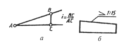
Rice. 26

Rice. 27

Rice. 28
so that its acute angle is directed towards the slope of the straight line (Fig. 26, b). The slope, like the taper, is specified in the drawing as a simple fraction, as a percentage or in ppm.
To designate a sphere in a drawing, use the sign of diameter or radius. In cases where it is difficult to distinguish a sphere from other surfaces in a drawing, the word “Sphere” may be added before the sign of the radius or diameter. The inscription on the drawing is made according to the type “Sphere diameter 17” or “Sphere R 10" (Fig. 27).
Simple flat parts are depicted in a single projection. In these cases, its thickness is indicated by a lowercase letter s and the inscription on the drawing is made according to the type s2 and is located on the shelf of the leader line (Fig. 28, a). The length of the object is indicated by the letter / (Fig. 28, b).
Chamfers in the drawings are applied in two linear dimensions (Fig. 29, A) or one linear and one angular (Fig. 29, b). In case if

Rice. 29
the angle of inclination of the cone generatrix is 45°, a simplified chamfer designation is used when the dimension line is drawn parallel to the axis of the cone, and the inscription is made as “2 x 45” (Fig. 29, c).
SELF-TEST QUESTIONS
1. What classification groups of ESKD standards exist?
2. How many sheets of A4 format are contained in A1 format?
3. What are the rules for placing the title block on the format?
5. What scale do you know?
6. How are scales designated?
7. What is the thickness of center, center, extension and dimension lines?
8. What lines are used to outline the outline?
9. What determines font size?
10. How is the height of lowercase letters determined?
11. What signs are used when applying dimensions?
12. At what distance from each other and from the contour line are the dimension lines drawn?
13. When is the diameter sign 0, and when is the radius sign R?
14. Where on the drawing is the size of the number applied relative to the dimension line?
15. How does the scale of the image affect the size of the dimensions applied in the drawing?
16. What is a slope, as is it indicated on the drawing?
17. What is taper, how is it indicated in the drawing?
18. How are conical chamfers indicated in the drawing?
Part three.