GOST PVC windows (plastic windows), aluminum, wooden window blocks, double-glazed windows
GOST PVC windows (plastic windows), aluminum, wooden window blocks, double-glazed windows
This section presents only current GOSTs for windows and double-glazed windows. Previously, other standards were in force, which were replaced by the standards listed below. You can download these documents for free.
Under each GOST for window units there is information about the date of introduction. The previous numbers of standards for windows that were in force before the entry into force of the updated standards are also indicated.
Regulatory framework plastic windows in our country has been formed by almost two dozen GOSTs, most of which are the reception of German and/or European standards, SNiPs and industry specifications, although it should be recognized that the package regulatory documents has not yet become sufficient, but only conditionally necessary to regulate all issues arising during the development, assembly, installation and operation of translucent structures based on PVC profile systems. The fundamental documents for the development of glazing structures for apartments, private houses, buildings, including premises specific for their purpose (attics, balconies, loggias, bay windows, verandas) are SNiP 02/23/2003 Thermal protection of buildings, MGSN 2.04-97 Acceptable levels noise, vibration and sound insulation requirements in residential and public buildings, GOST 30674-99 Window blocks made of polyvinyl chloride profiles and general GOST 23166-99 Window blocks. General technical conditions.
Here you need to understand that GOST 23166-99, which regulates the general provisions for windows made of wood, PVC, steel, aluminum, and the profile GOST 30674-99, in the development of which KVE specialists from the Profine GmbH production group were involved, despite being put into effect in one year have differences, although not contradictions, and therefore the basic document for plastic windows today is GOST 30674-99 Window blocks made of polyvinyl chloride profiles, as well as the accompanying GOST 30673-99 PVC profiles for window and door blocks. At the same time, GOST 30673-99, as well as SNiP 23-02-2003 in force today, are already morally outdated and many manufacturers of profile systems for the status of branded products have long gone beyond the norms of domestic acts, of course, in the direction of improving the mechanical and thermophysical characteristics of the profiles they produce . Some companies and production groups work according to their own standards and/or specifications, the stringency of the requirements for the quality characteristics of profile systems significantly exceeds the standards established in GOST 30673-99, which in general, when using appropriate double-glazed windows, makes it possible to reach the European level of thermal protection standards for translucent glass structures made of rigid PVC.
Similarly obsolete today are GOST 30778-2001 Sealing gaskets made of elastomeric materials for window and door units, GOST 10174-90 Sealing polyurethane foam gaskets for windows and doors and, even more so, GOST 19177-81 Rubber porous sealing gaskets, which do not cover the full range of modern seals for the contours of the ledges of plastic windows, as well as seals of sliding systems, which are mostly patented by manufacturers in last years and are effectively used by assembly companies or welded onto the profile during its manufacturing process.
GOST 30777-2001 Rotary, tilting and tilt-and-turn devices for window and balcony door units and GOST 5087-80 Handles for windows and doors became no less problematic in terms of information content and standardization, since well-known hardware manufacturers literally every year offer innovative design solutions for hardware fitting systems , integrating modern electronic control systems into them, adapted to new security systems for homes and buildings. Moreover, even mechanical sliding fittings for plastic structures for balconies, loggias, as well as parallel-exposed fitting complexes for plastic windows are not regulated at all by domestic GOSTs and so far the State Construction Committee is not carrying out work in this direction.
The regulatory framework for glass and double-glazed windows is in a slightly better position, the basis of which is GOST 111-2001 Flat glass, GOST 30698-2000 Tempered building glass, GOST 2486689 Glued double-glazed windows, as well as GOST 30733-2000 Glass with low-emission hard coating and GOST R 51136-98 Multilayer protective glass, although there are still no domestic regulations regulating selective glass, self-cleaning glass, curved glass, etc. as well as double-glazed windows with inert gas and vacuum, which are already sold in the USA and Japan, although in limited sizes. A GOST 30779-2001 Double-glazed windows for construction purposes. The method for determining weather resistance and assessing durability does not at all form an integrated approach to testing modern double-glazed windows in all their diversity and differences in thermophysical and mechanical characteristics.
Methods for assessing the performance characteristics of window structures, including those made from PVC profile systems, are set out quite fully and almost in accordance with European standards in GOST 26602.5-2001 Window and door units. Methods for determining resistance to wind loads, GOST 26602.4-99 Window and door blocks. Method for determining the total light transmittance, GOST 26602.3-99 Window and door blocks. Method for determining sound insulation, GOST 26602.2-99 Window and door blocks. Methods for determining air and water permeability, GOST 26602.1-99 Window and door blocks. Methods for determining heat transfer resistance. Many of these standards are copied from German DIN and this makes them conditionally relevant, although probably not for long.
The most recent standard of Gostroy today is GOST R 52749-2007 Window installation seams with vapor-permeable self-expanding tapes, in fact, duplicating GOST 30971-2002 Assembly seams of junctions of window blocks to wall openings, which was never implemented at the time due to recommendations, and not the binding nature of the normative provisions set out in it. At the same time, the vast majority of domestic companies, freelance installers and teams of shabashniks install plastic windows the old fashioned way with training to blow out the installation gaps construction foam, and control over the implementation of the current GOST R 52749-2007 is traditionally declarative for our country, but not real.
GOOD line (Z)
Characteristics
GOST for plastic windows. Basic guidelines for installing plastic windows.
Plastic windows are installed, most often, without prior consultation with the customer, because the cost of the window is reduced if a simple, cheap format is used. However, good quality windows must always be installed strictly in compliance with the standards of GOST 30971-2002, as well as GOST 23166-99, GOST 30674-99, GOST 24866-99 and GOST 30971-02.
GOST 23166-99 General windows
This standard defines the scope of application, general information about window blocks, basic terms and their classification. It is used when installing wooden, plastic and metal window and balcony blocks.
The standard is fundamental for a set of standards standards designed for certain types designs of window blocks and details of their configuration. When installing plastic windows, compliance with the rules of this standard is mandatory. In addition, this GOST is used for product certification. All window units must comply with the norms and requirements of this standard; their production must take into account the design and technological documentation approved in the prescribed manner.
Plastic window products manufactured in accordance with GOST 23166-99 must consist of certain frame elements, such as frames, sashes, leaves, vents, transoms. The corner joints of these elements of window frames are connected using glue and tenons, mechanical connections, welding or other methods. The standards provide design solutions that are mandatory for use in production corner connections for certain types of window products.
Constructive solutions for window units in mandatory must provide for ventilation of the premises using sashes, vents, transoms or ventilation valves. Experts recommend using devices in product designs to regulate humidity and temperature conditions: self-ventilation systems and climate valves.

The design of the product must provide for the possibility of installing and using several circuits of sealing gaskets located in the recesses for window units intended for use in poorly heated rooms. The designs of window products must take into account the possibility of replacing glass, sealing gaskets, various window devices and double-glazed windows without compromising the integrity of the product.
GOST 30674-99 PVC windows
This GOST defines the areas of application, classification of windows and their functions. This standard also defines the technical requirements for plastic windows. This standard is intended for control during the manufacture and installation of window and balcony door units made of polyvinyl chloride profiles in accordance with GOST 30673, their design is single, they are used in buildings and structures of various types.
In addition, the requirements of the standards apply to products that are glazed with sheet glass and are intended for use in unheated buildings. Specific product brands can be used depending on the existing operating conditions, taking into account SNiP and regulatory requirements GOST 23166.
Compliance with the requirements of this standard is mandatory.
Products are classified according to GOST 23166; their design options and type of surface finishing may vary for PVC profiles.
As you know, window blocks are divided into 1-4-chamber ones depending on the design of the PVC profile. Products are also divided depending on the type of finish; they are white, body-dyed, laminated and have a co-extruded front covering.
When placing an order for the supply or production of individual window products, you should indicate options for a design solution in accordance with GOST, include a description of profile structures and double-glazed windows, drawings indicating opening patterns, describe the types of window devices, and determine the requirements for appearance windows and other requirements. The installation of plastic windows must be carried out taking into account the requirements of GOST. in agreement with the manufacturer.
Technical requirements
Window profiles must comply with all the norms and requirements of these standards, GOST 23166, and be produced taking into account the design documentation, which is valid and approved in the prescribed manner. It is necessary to take into account the design of products consisting of frame elements that are welded from PVC profiles and reinforced with steel liners. IN window profiles imposts are fixed in frame elements using welding or mechanical connections. The design of products, with the exception of unheated rooms according to GOST, includes two or more rows of sealing gaskets in the recesses.
Among the main GOST standards used when installing plastic windows are GOST 24866-99 double-glazed windows and GOST 30971-02 installation seams.
They contain information about the scope of use of double-glazed windows, their list and classification, as well as basic parameters. GOST defines technical requirements and necessary recommendations for installation and installation of windows. GOST 30971-02 is used when installing window blocks and determines the classification of designs of various installation joints, regulatory technical requirements for the materials used, dimensions and surface preparation.
Instructions
Most likely, no one will argue with the fact that if installed incorrectly, even expensive windows are unlikely to work well. For this reason, if you plan to install your new windows yourself (at the same time taking upon yourself the entire burden of responsibility for the quality of installation), then in this case it will be useful for you to pay attention to the subtleties and a number of possible difficulties, which are rarely mentioned.
So: the biggest problem is correctly determining the size of your future windows. This is quite difficult, since an old wooden window is installed in the opening, which makes it very difficult to determine all the necessary measurements. It is for this reason that already at this stage a time bomb can be laid, which can turn any editing into a search for a feverish solution to the problem of breaking out of their deadlock. Therefore:
1. Rule No. 1:
The worker who takes measurements must have excellent spatial imagination and an analytical mind; he must be well acquainted with the design of future windows, and also possess personal experience installation Believe me, the combination of all these qualities may not occur very often. They are also not so easy to raise, so most often you have to make do with fewer requirements, hoping for chance, and problems that often arise have to be solved on the fly (over several years). What does a surveyor need to take into account so that the entire enterprise does not simply go down the drain, and installers do not spend the night on site?
2. Rule No. 2:
Measurements of your future window must be taken from both sides of the opening: inside (from the room), and also outside. Both of these parameters are needed in order to more accurately determine the depth of the window opening. Obviously, the window must be no smaller in size than the outer dimensions of the opening so that it does not fall out. But how much more this depends on a large number of difficult to predict factors, which we will discuss below.
3. Rule No. 3:
You should never forget to check whether the outline of the existing opening will be preserved on the outside for your next visit. After all, they can remove it from it old plaster, sew clapboard, lay an additional row of bricks, or a team of builders will generally expand it to incredible sizes without any prior notice.
4. Rule No. 4:
It is also necessary to take into account the fact that the window opening may be very skewed (this is especially true for panel houses). All this can lead to an increase in window sizes just by the amount of skew. That is, in order to prevent the formation of through gaps between the edge of the window opening and the window frame, the size of your window must be larger than outer size the window opening is approximately 35-40 mm in width and 12-18 mm in height. There are several ways to do this: you can increase overall dimensions window boxes or you can expand your window using additional profiles that snap onto the box.
5. Rule No. 5:
You need to make sure that your tastes and the taste of the customer completely coincide regarding the appearance of the windows from the street side. After all, some people like almost the entire window frame to be embedded in the wall and not be visible from the outside at all. Others prefer to show the window in all its glory. It's difficult to determine who is right here. If the first option is more preferable, then you should not forget about all sorts of distortions in the window opening, so as not to overdo it at all, when not only the window frame, but even part of the double-glazed window will be hidden inside the wall. The second option is more preferable, since there are fewer opportunities to make mistakes, as well as fewer consequences.
Contents ConstructionPortal. Ru WINDOW TECHNOLOGIES: INSTALLATION OF GLASS UNIT; HOW TO INSTALL AND ASSEMBLE GLASS UNIT Video - installation of plastic windows Installation of double glazed windows Plastic windows StroikaPortal. Ru How to install plastic windows in a wooden...
Contents Montage PVC windows according to GOST instructions Installation of PVC windows according to GOST instructions About the installation of KBE windows World of windows in St. Petersburg Installation of PVC windows according to GOST instructions installation of PVC windows...
Contents Installation in accordance with GOST GOST installation of window sills What does the installation of plastic windows mean in accordance with GOST GOST 30971 Installation of a window sill - technical process! Installation in accordance with GOST Installation in accordance with GOST Installation stages...
page 1

page 2

page 3

page 4

page 5

page 6

page 7

page 8

page 9

page 10

page 11

page 12

page 13

page 14

page 15

page 16

page 17

page 18

page 19

page 20

page 21

page 22

page 23

page 24

page 25

page 26

page 27

page 28

page 29

page 30
The permissible ratio of the height and width of the opening elements of specific brands of products, taking into account the opening pattern, types of profiles and window devices used, the moment of inertia of the reinforcing liners and the weight of the sash elements, is established in the technical documentation.
5.1.5 Products must be safe to use and maintain. The safety conditions for using products of various designs are established in the design documentation (for example, window units with suspended opening of the sashes are not recommended for use in children's institutions). Products must be designed for operating loads, including wind loads, in accordance with current building codes.
5.1.6 Products (or materials for their manufacture and components) must have documents on sanitary safety provided for by current legislation and drawn up in the prescribed manner.
5.2 Dimensions and requirements for maximum deviations
5.2.1 Overall dimensions and architectural drawings of window units - in accordance with GOST 23166.
The nominal dimensions of sections of profiles, reinforcing liners, combinations of profiles are established in the technical documentation for their manufacture.
5.2.2 Limit deviations The nominal overall dimensions of the product should not exceed mm.
5.2.3 Maximum deviations from the nominal dimensions of product elements, gaps in the rebates and under the overlap, the dimensions of the location of window devices and hinges must not exceed the values established in Table 1.
Table 1
In millimeters
|
Size interval |
Maximum deviations of nominal sizes |
||||
|
inner size boxes |
outer dimensions of the sashes |
gap in the vestibule (rebate) |
clearance under fusion |
Dimensions of arrangement of devices and hinges |
|
|
From 1000 to 2000 |
|||||
|
Notes 1 The maximum deviation values are established for the temperature range of measurements - 16 - 24 °C. 2 The values of the maximum deviations of the dimensions of the gaps in the rebates and under the overlap are given for closed sashes with installed sealing gaskets. |
|||||
The difference in the lengths of the diagonals of rectangular frame elements should not exceed 2.0 mm with the longest side length of the sash up to 1400 mm and 3.0 mm - more than 1400 mm.
5.2.4 The difference in the front surfaces (sag) in welded corner and T-shaped connections of adjacent profiles of frames and sashes, the installation of which is provided in the same plane, should not exceed 0.7 mm, when mechanically connecting the imposts with the profiles of the frames, as well as with each other - no more than 1.0 mm.
5.2.5 If the processing of a weld involves making a groove, the size of the groove on the front surfaces should not exceed 5 mm in width, the depth of the groove should be in the range of 0.5 - 1.0 mm, and the cut size of the outer corner of the weld should not must exceed 3 mm along the weld seam.
5.2.6 The sagging of opening elements (sashes, leaves, vents) in the assembled product should not exceed 1.5 mm per 1 m of width.
5.2.7 The deviation of the nominal size of the distance between the overlaps of adjacent closed doors should not exceed 1.0 mm per 1 m of the length of the rebate.
5.2.8 Deviations from the straightness of the edges of parts of frame elements should not exceed 1 mm per 1 m of length in any section.
5.3 Characteristics
5.3.1 The main operational characteristics of products with three-chamber profiles of frames and sashes are given in Table 2.
table 2
|
The name of indicators |
Indicator value |
|
|
Reduced heat transfer resistance, m 2 °C/W, not less than: |
||
|
with single-chamber glass |
||
|
4M 1 -16Ar-I4 |
||
|
with double-glazed windows; |
||
|
4M 1 -8-4 M 1 -8-4M 1 |
||
|
4M 1 -10-4M 1 -10-4M 1 |
||
|
4M 1 -10Ar-4M 1 -10Ar-4M 1 |
||
|
4M 1 -12-4M 1 -12-4M 1 |
||
|
4M 1 -12Ar-4M 1 -12Ar-4M 1 |
||
|
with double-glazed windows with heat-reflecting coating |
||
|
4M 1 -8-4M 1 -8-K4 |
||
|
4M 1 -8-4M 1 -8-И4 |
||
|
4M 1 -8Ar-4M 1 -8Ar-K4 |
||
|
4M 1 -8Ar-4M 1 -8Ar-I4 |
||
|
4M 1 -12-4M 1 -12-K4 |
||
|
4M 1 -12-4M 1 -12-И4 |
||
|
4M 1 -12Ar-4M 1 -12Ar-K4 |
||
|
4M 1 -12Ar-4M 1 -12Ar-I4 |
||
|
Insulation airborne noise transport flow, dBA, not less |
||
|
Sound insulation class, not lower |
||
|
Total light transmittance (reference value) |
||
|
Air permeability at DP = 10 Pa, m 3 / (h×m 2), no more |
||
|
Air and water permeability class, not lower |
||
|
Reliability of window devices and hinges, the “opening-closing” cycle |
||
|
Durability, conditional years of operation: |
||
|
PVC profiles |
||
|
double-glazed windows |
||
|
sealing gaskets |
||
|
Notes 1 The reduced heat transfer resistance of the opaque part of the filling of balcony door blocks must be no less than 1.3 times higher than the heat transfer resistance of the transparent part of the products, but not lower than 0.8 m 2 °C/W. The values of the reduced heat transfer resistance of a combination of product profiles should not be lower than this indicator for double-glazed windows by more than 15%. 2 The values of the reduced heat transfer resistance are established for products with a ratio of glazing area to product area equal to 0.7, and an average thickness of the profile combination of 58 - 62 mm. 3 The deadline for entering the durability indicators indicated in brackets is 07/01/2002. |
||
Indicators of reduced heat transfer resistance for products made from profiles with a different number of chambers and a different glass unit design are taken based on the results of laboratory tests.
5.3.2 Resistance to static loads and forces applied to the doors to open and close them - according to GOST 23166.
5.3.3 Welded corner connections with machined weld seams of sashes up to 1000 mm wide must withstand the test load applied according to diagram A of Figure 9, not less than:
750 N - with sash height up to 1300 mm;
800 N - for sash heights over 1300 to 1500 mm;
900 N - for sash heights over 1500 to 1800 mm;
1000 N - with a glazing area of 2.1 - 2.3 m2 and for door frames.
The value of loads when testing the strength of corner joints of sashes with a width of over 1000 to 1200 mm is increased by 10%.
The value of loads when testing the strength of corner connections of boxes according to scheme A in Figure 9 is not less than 800 N, according to scheme B - 1600 N.
When tested according to scheme B of Figure 9, corner joints must withstand a load doubled.
5.3.4 The strength values of corner connections of frame elements in the case of using profiles of classes B and C according to GOST 30673 are established in the regulatory and design documentation for these types of products.
5.3.5 Appearance of products: color, gloss, permissible defects
the surfaces of PVC profiles (risks, scratches, shrinkage cavities, etc.) must correspond to standard samples approved by the head of the product manufacturer.
Welded seams should not have burns, uncooked areas, or cracks. Changing the color of PVC profiles in places welds after their stripping is not allowed.
5.3.6 The front surfaces of profiles of doors and product boxes (except curved ones) must be protected with self-adhesive film.
5.4 Requirements for components and their installation
5.4.1 Materials and components used for the manufacture of window units must comply with the requirements of standards, technical specifications, and technical certificates approved in the prescribed manner.
5.4.2 The main components of the products: PVC profiles, double-glazed windows, sealing gaskets, window devices must be tested for durability (failure-free operation) in testing centers accredited to conduct such tests.
5.5 Requirements for PVC profiles
5.5.1 Polyvinyl chloride profiles must be made from rigid, unplasticized polyvinyl chloride, modified for high impact strength and resistance to climatic influences, and meet the requirements of GOST 30673, as well as technical specifications for specific profile systems approved in accordance with the established procedure.
By agreement between the consumer and the manufacturer, it is allowed to manufacture products from PVC profiles of other colors and types of finishing of the front surfaces. The use of colored profiles painted in the mixture without a protective decorative coating on surfaces exposed to ultraviolet rays, not allowed.
5.5.3 Curved profiles should not have deviations from the shape (warping, waviness) exceeding the width and height of the profile (±1.5) mm. The recommended minimum bending radius for white PVC profiles should be taken equal to five times the profile width, for other profiles - 5.5 times the profile width.
5.6 Requirements for glazing, door panels and sealing gaskets
5.6.1 For glazing products, single- or double-glazed windows are used in accordance with GOST 24866, glass in accordance with GOST 111, as well as in accordance with regulatory documentation for specific types of translucent filling of window blocks.
5.6.2 To increase architectural expressiveness, installation is allowed decorative layouts(slabs) on the outer surfaces of double-glazed windows using weather-resistant adhesives or the use of double-glazed windows with an internal frame (Figure 4).
5.6.3 Double-glazed windows (glass) are installed in the rebate of the sash or frame on pads that prevent the edges of the double-glazed window (glass) from touching the internal surfaces of the rebates of PVC profiles.
Depending on the functional purpose linings are divided into basic, supporting and spacer.
A- profiles of the internal frame of the double-glazed window; b - overhead decorative layouts; V - option for the combined use of overhead layouts and the internal frame of a double-glazed window; G - binding connections of layouts
Figure 4 - Options for installing decorative layouts
To provide optimal conditions To transfer the weight of the glass unit to the structure of the product, support pads are used, and to ensure the nominal dimensions of the gap between the edge of the glass unit and the fold of the sash, spacer pads are used.
Base pads are used to level bevels and folds and are installed under support and spacer pads. The width of the base pads must be equal to the width of the rebate, and the length must be no less than the length of the support and spacer pads.
Support and spacer pads can combine the functions of basic pads.
The length of the support and spacer pads should be from 80 to 100 mm, the width of the pads should be at least 2 mm greater than the thickness of the glass unit.
5.6.4 Linings are made of rigid weather-resistant polymer materials. The recommended hardness value of the support pads is 75 - 90 units. according to Shore A.
5.6.5 Methods of installation and (or) design of pads must exclude the possibility of their displacement during transportation and operation of the products.
5.6.6 The design of the linings should not impede air circulation over the inner surface of the glazing rebate.
5.6.7 If the installation location of the lining coincides with the head of the fastening screw, the lining must not be skewed.
5.6.9 The distance from the pads to the corners of the double-glazed windows should, as a rule, be 50 - 80 mm. If the width of the glass unit is more than 1.5 m, it is recommended to increase this distance to 150 mm.
5.6.10 The basic layout of support and spacer pads when installing double-glazed windows, depending on the type of opening of window units, is shown in Figure 5. In balcony door units and in products with reinforced locking devices, it is recommended to install additional pads in the locking areas.
Types of opening window units: A- non-opening; b - tilt and turn; V- rotary (swing); G - folding; d - hanging; e - installation of linings in figured window blocks
Support pads
Distance pads
Drawing 5 - Layout diagrams of support and spacer pads when installing double-glazed windows, depending on the type of opening of window units
5.6.11 It is recommended to make opaque fillings of balcony door panels (panels) from three-layer panels consisting of plastic or aluminum facing sheets filled with insulation. In panels of products intended for use in unheated rooms, it is allowed to use sheet or facing materials without insulation.
5.6.12 Installation of panels in door leaves is carried out in accordance with the requirements for the installation of double-glazed windows.
5.6.13 Design solutions for fastening units for double-glazed windows, as well as panels for filling the opaque part of the door leaf, must exclude the possibility of their dismantling from outside.
5.6.14 Installation of double-glazed windows (glasses), as well as sealing of the sashes, is carried out using elastic polymer sealing gaskets. It is allowed to use glazing beads with a co-extruded seal for fastening double-glazed windows from the inside.
5.6.15 Sealing gaskets must be resistant to climatic and atmospheric influences.
5.6.16 The fit of the sealing gaskets must be tight, preventing the penetration of water.
5.6.17 Sealing gaskets must be installed continuously along the entire perimeter of the sashes and double-glazed windows. When installing in a ring, the joint of the gaskets should be in the upper part of the product. When installing gaskets with joints at 45° corners, the joints of the gaskets should be welded or glued (except for gaskets installed in glazing beads). Corner bends and welded joints of sealing gaskets for double-glazed windows should not have protrusions (bulges) that cause concentrated loads on the double-glazed windows.
It is allowed to disrupt the continuity of installation of gaskets in the sash vestibule in structures that provide for self-ventilation of products, as well as in other cases provided for by design solutions and established in the design documentation.
5.7 Requirements for reinforcement inserts
5.7.1 The main PVC profiles of the products are reinforced with steel liners with anti-corrosion coating.
5.7.2 The shape, wall thickness and moments of inertia of the reinforcing liners, as well as the maximum permissible dimensions of the valves when using specific types of liners are established in the technical documentation for the manufacture of products.
5.7.3 Reinforcing liners must fit into the internal chambers of PVC profiles tightly, by hand, without the help of special devices.
5.7.4 When using profiles white reinforcing liners may not be installed (except for imposts) in parts of products whose length is less than 700 mm.
When using colored profiles, as well as in the details of frost-resistant window blocks and in special cases when this is required according to the documentation of the manufacturers of PVC profiles, the installation of reinforcing liners is mandatory in all parts of the products.
5.7.5 The wall thickness of the reinforcing liners must be at least 1.2 mm; to strengthen colored and frost-resistant profiles, it is recommended to use reinforcement liners with a wall thickness of at least 1.5 mm.
5.7.6 The distance from the liner to the corner (end) of the reinforced part of the profiles should be within 10 - 30 mm. In the designs of products with glass units weighing more than 60 kg, as well as in reinforced products, it is recommended to use liners trimmed at an angle of 45°. Examples of installation of reinforcing inserts are shown in Figure 6.
Figure 6 - Examples of installation of reinforcement inserts
The length of the reinforcing mullion liners when they are mechanically attached to the box liners is determined by the design of the connection.
5.7.7 Joining or breaking of reinforcing liners along the length within the same PVC profile is not allowed.
5.7.8 Each reinforcing liner is attached to the non-front side of the PVC profile with at least two self-tapping screws (screws) according to regulatory documentation (hereinafter referred to as ND). Distance from internal corner(weld seam) to the nearest installation location of the self-tapping screw should not exceed 80 mm.
The fastening pitch should be no more than: 400 mm for white profiles, 300 mm for other types of profiles, as well as for frost-resistant profiles.
5.7.9 Steel reinforcing liners must be protected with a zinc coating with a thickness of at least 9 microns in accordance with GOST 9.303.
Omissions and damage to the coating are not allowed.
5.8 Requirements for window devices
5.8.1 When manufacturing products, window devices and fasteners are used that are specifically designed for use in window systems made of PVC profiles.
5.8.2 The type, number, location and method of fastening of locking devices and hinges are established in the working documentation, based on the size and weight of the opening elements of the product, as well as the operating conditions of the window units. In this case, the distance between hinges and locking points, as a rule, should not exceed 800 mm.
5.8.3 It is recommended to fasten the hinges using self-tapping screws through at least two PVC profile walls with a total thickness of at least 4.5 mm or through one profile wall and a reinforcing liner. If it is necessary to drill holes for screws, their diameter should be equal to the diameter of the central core of the screw.
When the opening elements weigh more than 60 kg, as well as in balcony door blocks and reinforced products, it is recommended to fasten the hinges into reinforcing inserts.
5.8.4 It is recommended to use adjustable hinges in products, devices for tilt-and-turn opening that provide slot ventilation, as well as ventilation with an adjustable opening angle, using safety locks against accidental opening (including when the devices are positioned in ventilation mode).
To ensure a fixed gap between the lower profiles of the sashes and frames, it is recommended to use guides (impedance) pads, rollers or special fittings.
5.8.5 Locking devices must ensure reliable locking of opening elements of products. Opening and closing should occur easily, smoothly, without jamming. Handles and bolts of appliances should not move spontaneously from the “open” or “closed” position.
5.8.6 The designs of locking devices and hinges must ensure tight and uniform compression of the gaskets along the entire sealing contour in the recesses.
5.8.7 Window fittings and fasteners must meet the requirements of GOST 538 and have a protective and decorative (or protective) coating in accordance with GOST 9.303.
Window devices must withstand the loads and forces applied to them in accordance with GOST 23166.
5.9 Design requirements
5.9.1 Corner connections of PVC profiles of frame elements must be welded. The design strength of welded joints is given in the design documentation.
To strengthen welded joints in the corners of balcony block panels with a width of more than 800 mm, it is recommended to use welded polyvinyl chloride liners connected with screws to reinforcing liners. An example of installing liners is shown in Figure 7.
5.9.2 Impost parts are attached to adjacent PVC profiles of the frame (sash) using steel or plastic fasteners, screws or screws. Examples of fastening imposts are shown in Figure 8.
It is allowed to use welded T-shaped and cross-shaped connections of imposts. In this case, the strength of the connections must be no lower than the strength established for corner connections.
5.9.3 Corner and T-shaped connections of profiles must be sealed. It is allowed to seal the mechanical connections of PVC profiles with weather-resistant elastic gaskets. Gaps up to 0.5 mm can be sealed with special sealants that do not impair the appearance of the products and protect the connections from moisture penetration.
Drawing 7 - Insert for strengthening corner joints
Figure 8 - Examples of fastening imposts
5.9.4 Product designs must include a system of holes: for draining the cavity between the edges of the glass unit and the folds of the profiles; water drainage; wind pressure compensation; reducing heating of colored profiles.
5.9.5 Each glazing field must have holes for draining the cavity between the edges of the glass unit and the folds of the profiles. The holes should be located in the deepest parts of the folds and not have burrs that prevent water drainage. For systems with a middle seal, the holes must be located in front of the middle seal on the outside.
In the lower profile of the sash there must be at least two holes with a maximum distance between them of 600 mm, in the upper profile with a length of up to 1 m - two holes, and more than 1 m - three. Recommended hole sizes are at least 8 mm in diameter or at least 5´10 mm in size.
The location of the holes should not coincide with the installation locations for the linings under the double-glazed windows. The holes in the profile walls must be offset relative to each other by at least 50 mm.
5.9.6 The lower profiles of boxes and horizontal imposts must have at least two drainage holes measuring at least (5´20) mm, the distance between which should be no more than 600 mm.
The drainage holes must be offset in the profile walls by at least 50 mm. The holes must not have burrs that would impede water drainage.
For systems with a middle seal, the slots must be located in front of the middle seal on the outside.
The holes on the front surface of the box should be protected with decorative visors.
5.9.7 For systems with external and internal seals and for systems with three sealing circuits, when installing products at a height of more than 20 m, it is recommended to make holes in the upper horizontal profiles of the frames to compensate for wind pressure in the cavity between the frame and the sash.
Holes for compensating wind pressure must have a diameter of at least 6 mm or a size of at least (5´10) mm in the upper profile of the box. If the length of the box profile is up to 1 m, two holes are drilled, and more than 1 m - three.
To compensate for wind pressure, it is allowed to remove the outer seal in sections of 30 mm in length in the upper profile of the box.
5.9.8 Functional openings should not pass through the walls of the main chambers of the profiles.
5.9.9 In the case of using colored profiles, it is recommended (for ventilation of external chambers in order to avoid their overheating when exposed to sun rays) fulfill through holes through the walls of the outer chambers of the profiles of the doors and frames with a diameter of 5 - 6 mm.
5.9.10 The number and location of all types of holes are established in the working documentation. In this case, the influence of drainage holes on adjacent functions of products (sound, heat insulation, etc.) should be taken into account.
5.9.11 The depth of pinching of a double-glazed window (glass) in the folds of profiles, as well as the depth of pinching by glazing beads, should not be less than 14 mm.
5.10 Completeness
5.10.1 The configuration of products when delivered to the consumer must meet the requirements established in the order.
5.10.2 Finished products must have installed instruments, double-glazed windows, sealing gaskets and protective film on facial surfaces. A set of products may include additional, connecting and other profiles for various purposes in accordance with GOST 30673. Component profiles, parts of locking devices protruding beyond the plane of the product, as well as decorative visors may be supplied unmounted with the products.
By agreement between the manufacturer and the consumer, separate transportation of double-glazed windows is allowed, and the consumer must be provided with a diagram for installing linings under the double-glazed windows.
5.10.3 The delivery package must include a quality document (passport) and instructions for use of the products.
5.10.4 At the consumer’s request, the manufacturer provides him with standard instructions for the installation of window units, and also completes the products with materials for caring for the products in accordance with the requirements of the operating instructions.
5.11 Marking
5.11.2 The main profiles, window devices and double-glazed windows included in the product must be marked in accordance with the RD for these products.
6 Acceptance rules
6.1 Products must be accepted by the technical control of the manufacturer for compliance with the requirements of this standard, as well as the conditions specified in the contract for the manufacture and supply of products.
Confirmation of acceptance of products by technical control of the manufacturer is their marking, as well as the execution of documents on acceptance and quality of products.
Products are accepted in batches. When accepting products at the manufacturing enterprise, the number of products manufactured within one shift and issued with one quality document is taken as a batch.
6.2 The product quality requirements established in this standard confirm:
incoming inspection of materials and components;
operational production control;
acceptance control of finished products;
control acceptance tests of a batch of products carried out by the quality service of the manufacturer;
periodic testing of products in independent testing centers;
qualification and certification tests.
6.3 The procedure for conducting incoming inspection and operational production control at workplaces is established in the technological documentation.
If the manufacturer completes window units with components self-made, they must be accepted and tested in accordance with the requirements of regulatory documentation for these products.
6.4 Acceptance quality control finished products carried out individually, using the method of continuous control. In this case they check:
appearance of products;
deviations in the size of gaps under the overlay;
sagging of opening elements;
deviation in the size of the distance between the flaps of the valves;
presence and location of holes;
operation of window devices and heifers;
the presence of a protective film on the front surfaces.
Finished products that have passed acceptance control are marked. Products that do not pass acceptance control for at least one indicator are rejected.
6.5 Products must undergo control acceptance tests carried out by the quality service of the manufacturer at least once per shift. At the same time, they control:
deviations of nominal dimensions and straightness of edges;
strength of corner joints;
requirements for installing linings under double-glazed windows;
requirements for installation of sealing gaskets;
requirements for installation of reinforcing liners;
location and operation of window fixtures;
requirements for the quality of welds;
requirements for appearance and presence of protective film;
requirements for size, number and location functional holes;
requirements for labeling and packaging.
Tests are carried out on three samples.
In the case of a negative test result for at least one indicator, the quality of products is re-checked on twice the number of samples for the indicator that had a negative test result. If a non-compliance of the indicator with the established requirements is detected again, the controlled and subsequent batches of products are subjected to continuous control (grading). If the result of continuous control is positive, they return to established order acceptance tests.
In case of a negative test result in terms of the strength of corner joints, repeated tests are carried out on twice the number of samples. If the result of repeated tests is unsatisfactory, the batch is rejected, and production of the products is stopped until the cause of the defect is eliminated.
6.6 Periodic tests for performance indicators specified in 5.3.1 - 5.3.3 are carried out when changes are made to the design of products or their manufacturing technology, but at least once every five years, as well as during certification of products (in terms of indicators provided for by the methods certification).
Qualification tests of products are carried out when products are put into production. In justified cases, it is allowed to combine qualification and certification tests.
Tests are carried out in independent testing centers accredited to conduct them.
6.7 The consumer has the right to carry out quality control checks of products, while observing the sampling procedure and test methods specified in this standard.
When accepting products by the consumer, a batch is considered to be the number of products shipped according to a specific order, but not more than 500 pieces, documented in one quality document.
Table 3
|
Batch volume, pcs. |
Sample size, pcs. |
Acceptance number |
|
|
minor defects |
critical and significant defects |
||
|
Complete control |
|||
|
Note - Significant and critical defects include defects leading to loss of performance characteristics that cannot be eliminated without replacing parts of the product (breakage of a profile or window fixtures, cracked glass unit, etc.), exceeding the maximum dimensional deviations by more than 1.5 times from those established in the RD, lack of completeness of products. Minor defects include removable defects: minor surface damage, unadjusted window devices and hinges, exceeding the maximum dimensional deviations by less than 1.5 times from those established in the RD. |
|||
By agreement of the parties, acceptance of products by the consumer can be carried out at the manufacturer’s warehouse, at the consumer’s warehouse or wine , location specified in the supply contract.
6.9 Each batch of products must be accompanied by a quality document (passport) in accordance with GOST 23166.
6.10 Acceptance of products by the consumer does not relieve the manufacturer from liability if hidden defects that led to a violation of the performance characteristics of products during the warranty period.
7 Control methods
7.1 Methods of incoming and production operational quality control are established in the technological documentation.
7.2 Control methods for acceptance inspection and acceptance testing
7.2.1 The geometric dimensions of products, as well as the straightness of the edges, are determined using the methods established in GOST 26433.0 and GOST 26433.1.
Maximum deviations from the nominal dimensions of product elements, the difference in diagonal lengths and other dimensions are determined using a metal measuring tape in accordance with GOST 7502, calipers in accordance with GOST 166, probes in accordance with ND.
Maximum deviations from the straightness of the edges are determined by applying a straight edge in accordance with GOST 8026 or a building level with a flatness tolerance of at least the ninth degree of accuracy in accordance with GOST 9416 to the part being tested and measuring the largest gap using feeler gauges. .
Measurements linear dimensions should be carried out at the air temperature of the products (20 ± 4) °C. If it is necessary to carry out measurements at other temperatures, the temperature change in the linear dimensions of the profiles should be taken into account: 0.8 mm/m for every 10 °C deviation from the specified temperature.
7.2.2 The maximum deviations of the nominal dimensions of the gaps under the overlay are checked using a set of feeler gauges. The gaps in the rebate are determined with a caliper by measuring adjacent cross-sectional dimensions.
7.2.3 The sag in the mating of adjacent parts is determined with a feeler gauge as the distance from the edge of a metal ruler according to GOST 427, applied to the upper mating surface, to the lower surface.
7.2.4 The appearance and color of products (including in places of welds) are assessed by comparison with standard samples approved in the prescribed manner.
Differences in color, gloss and surface defects visible to the naked eye from a distance of (0.6 - 0.8) m in natural light of at least 300 lux are not allowed.
7.2.5 The tight fit and correct installation of sealing gaskets, the presence and location of pads, functional holes, window devices, fasteners and other parts, the color and absence of cracks in welded joints, the presence of a protective film, markings and packaging are checked visually. To determine the tightness of the sealing gaskets, compare the dimensions of the gaps in the recesses and the degree of compression of the gaskets, which should be at least 1/5 of the height of the uncompressed gasket. Measurements are made with a caliper.
The tightness of the sealing gaskets in closed casement vestibules can be determined by the presence of a continuous trace left by a coloring agent (for example, colored chalk) previously applied to the surface of the gaskets and easily removed after inspection.
7.2.6 Determination of strength (load-bearing capacity) of fillet welded joints.
To test the strength of fillet welded joints, the load application diagrams shown in Figure 9 are used.
1 - support; 2 - stop (for scheme B - carriage); 3 - sample; 4 - load application point; 5 - removable fastening clamps
Figure 9 - Schemes for applying loads when determining the strength of fillet welded joints
The test procedure is in accordance with GOST 30673 with the following additions.
Weld seams are cleaned according to the accepted technology for manufacturing window blocks.
Samples are tested with reinforcing inserts inserted into them.
The magnitude of the loads is taken according to 5.3.3, the control method is non-destructive, exposure under load is at least 3 minutes.
The test result is considered satisfactory if each sample withstood the load without destruction or cracking.
7.2.7 The operation of window devices is checked by opening and closing the sash elements of the product five times. If deviations are detected in the operation of window devices, they are adjusted and rechecked.
7.3 Methods of control during periodic testing
7.3.1 The strength (bearing capacity) of fillet welded joints is determined according to 7.2.6.
When conducting tests, the use of other load patterns and test equipment is permitted. In this case, test methods, including processing of results, must be correlated with the test method in 7.2.6.
7.3.2 The reduced heat transfer resistance is determined according to GOST 26602.1.
7.3.3 Air permeability is determined according to GOST 26602.2.
7.3.4 Sound insulation is determined according to GOST 26602.3.
7.3.5 The total light transmittance is determined according to GOST 26602.4.
7.3.6 Resistance to static loads is determined according to GOST 24033.
7.3.7 Indicators of durability (including resistance to climatic and atmospheric loads), reliability of window devices, as well as the forces applied to window devices are determined according to methods approved in the prescribed manner.
8 Packaging, transportation and storage
8.1 Packaging of products must ensure their safety during storage, loading and unloading operations and transportation.
8.2 Devices or parts of devices that are not installed on the products must be packaged in plastic film in accordance with GOST 10354 or in other packaging material that ensures their safety, tightly bandaged and supplied complete with the products.
8.3 Opening doors of products must be closed with all locking devices before packaging and transportation.
8.4 Products are transported by all modes of transport in accordance with the rules for the carriage of goods in force for this type of transport.
8.5 When storing and transporting products, they must be protected from mechanical damage, exposure to precipitation, significant temperature fluctuations and direct sunlight.
8.6 When storing and transporting products, it is not allowed to stack them on top of each other; it is recommended to install gaskets made of elastic materials between the products.
8.7 Products are stored in a vertical position at an angle of 10 - 15° to the vertical on wooden pads, pallets or in special containers in covered areas without direct contact with heating devices.
8.8 In the case of separate transportation of double-glazed windows, the requirements for their packaging and transportation are established in accordance with GOST 24866.
9 Manufacturer's warranty
9.1 The manufacturer guarantees that products comply with the requirements of this standard, provided that the consumer complies with the rules of transportation, storage, installation, operation, as well as the scope of application established in the regulatory and design documentation.
9.2 The guaranteed shelf life of products is 1 year from the date of shipment of the product by the manufacturer.
9.3 The warranty service life of products is established in the supply contract, but not less than 3 years from the date of shipment of the products by the manufacturer.
APPENDIX A
(informative)
Terms and Definitions
For the purposes of this standard, the following terms and corresponding definitions apply.
Profile system- a set (set) of PVC profiles and components combined into a complete structural system, documented by design documentation.
Profiles- parts of window blocks made by extrusion, with specified shapes and cross-sectional dimensions.
Profile width- the largest size between the front outer and inner surfaces of the profile.
Profile height- largest size cross section profile in a direction perpendicular to the width of the profile.
Camera- a closed internal cavity (system of cavities) of a PVC profile, located perpendicular to the direction of heat flow. The chamber may consist of a number of subchambers separated by partitions. Chambers and subchambers can perform various specified functions, for example, for installing reinforcement inserts or as self-ventilation channels.
fold- part of the profile surface formed by the protrusion of one of its parts.
Backlash - the distance between the sash and the frame, established based on the conditions for the normal functioning of locking window devices.
Narthex- the place where the sash connects with the frame bars (main vestibule), with the impost (impost porch) or with the sash (impostless, frame porch).
Floating- a protrusion in the narthex assembly, formed by the protruding part of the frame (sash) and overlapping the sash (frame) by the size in the narthex under the overlay.
Reinforcing liner- a profile steel element installed in the internal chamber of the main profile to absorb operational loads.
Profile combination- a connection unit for mating profiles (for example, a frame profile - a sash profile with a glazing bead; an impost profile - a sash profile with a glazing bead; a sash profile with a bead and a glazing bead - a sash profile with a glazing bead).
Main profiles - profiles of frames, sashes, imposts, frames, which perform a strength function as an integral part of window and balcony door structures.
Additional profiles- profiles that do not perform a strength function as an integral part of window and balcony door structures.
Glazing beads (layouts on glass) - additional profiles designed for fastening double-glazed windows.
Glazing beads can be manufactured with a co-extruded sealing gasket.
Connecting profiles (connectors) - profiles designed for blocking windows and balconies door frames with each other in structures consisting of two or more products. Connectors can connect frame profiles at different angles and are selected taking into account strength requirements.
Expansion profiles (expanders)- profiles designed to increase the height of the window frame profile.
Gorbylki- profiles intended for dividing the glazing fields of sashes.
Decorative overlays- invoices decorative profiles, glued to the glass unit from the inside and outside and forming a false binding.
Low tides- profiles designed to drain water from the window structure.
Cladding profiles- profiles for finishing window slopes (corners, trims, trims, etc.). Cladding profiles can form various systems.
Adjustable ventilation- organization of ventilation of rooms with different air exchange rates due to design solutions of products.
Self-ventilation- a system of limited air exchange through the channels of profile chambers or through climate valves built into window units in order to regulate the air humidity in the room and prevent condensation on the internal surfaces of the windows.
Durability- characteristics of products that determine their ability to preserve performance for a given period, confirmed by the results of laboratory tests and expressed in conventional years of operation (service life).
Definitions of the main parts, dimensions and functional areas of profile combinations are given in Figures A.1 and A.2.
1 - box; 2 - outer seal gasket; 3 - base lining; 4 - support pad; 5 - external sealing gasket of a double-glazed window; 6 - internal sealing gasket of a double-glazed window; 7 - double-glazed window; 8 - glazing bead; 9 - reinforcing sash liner; 10 - sash; 11 - Internal seal gasket; 12 - reinforcement box insert
Figure A.1 - Basic details of the profile combination
A - height of the combination of profiles; A 1 - height of the sash profile; A 2 - height of the box profile; B - width of the profile combination; B 1 - sash profile width; B 2 - box profile width; a 1 - the size of the gap (the gap in the vestibule); and 2 - the size of the vestibule under the raft; and 3 - the height of the rebate (quarter) of the glazing; and 4 is the pinching height of the glass unit; b 1 - size of the gap under the overlay; b 2 - glass thickness
Figure A.2 - Main dimensions and functional areas profile combination details
Composition of working documentation for window and balcony door units
Documentation for the production of window and balcony door blocks from PVC profiles must contain the following data:
B.1 Window and door units
The design description must include:
methods and schemes for opening windows;
methodology for calculating basic and functional dimensions;
tables (diagrams) of the maximum permissible dimensions (proportions) of sashes;
types and sizes of reinforcement liners used depending on the sizes of sashes, frames, imposts, crossbars;
drawings of the location of holes for water drainage, drainage of glazing rebates, compensation of wind pressure, indicating their number and size;
number and location of locking devices;
additional requirements for windows made of colored profiles.
B.2 PVC profiles:
sections of profiles indicating their functions and division into main and additional profiles, profile articles;
basic and functional dimensions of profiles;
sections of profile combinations with main dimensions;
information about the physical and mechanical characteristics and durability of PVC profiles.
B.3 Reinforcing inserts:
material;
type and thickness of anti-corrosion coating;
sections with main dimensions;
moments of inertia ( E´ J),
B.4 Sealing gaskets:
B.5 Glazing:
table with possible combinations of double-glazed windows, sealing gaskets and glazing beads;
installation diagram for glazing pads.
B.6 Profile connections(corner, impost, etc..):
for welded joints - design strength for all main profiles;
for mechanical connections - a description of connecting parts, reinforcements, fasteners, sealing gaskets and sealants.
B.7 Window fittings and hinges:
opening options;
designation of various types of window devices;
locations of devices and loops;
restrictions on the weight and size of the valves;
characteristics of protective and decorative coating;
conditions for adjusting locking devices and hinges.
B.8 Technological documentation for the manufacture of windows:
Technological documentation for the manufacture of windows must include process maps, technological regulations, including quality control regulations, and other necessary documents.
B.9 Standard instructions for installation of products
B.10 Product operating instructions
General requirements for installation of products are given in Appendix D.
System of functional holes and intra-profile duct self-ventilation
(Figures B.1-B.3)
1 - drainage holes; 2 - holes for draining the cavity between the edges of the glass unit and the folds of the profiles; 3 - holes for compensating wind pressure; 4 - holes for ventilation of external chambers of colored profiles
DrawingB.1 - Functional hole system
Figure B.2 - Location of functional holes
1 - the gap between the frame and the sash through which outside air enters the chamber before the middle seal. The external seal is installed only in the upper frame of the box; 2 - a special ventilation chamber in the upper frame of the frame, through which air penetrates into the cavity between the frame and the sash behind the internal seal; 3 - a system of offset holes in the sash through which air penetrates into the room; 4 - sound-absorbing pillows at the ends of the ventilation chamber in the top bar of the box
Figure B.3 - In-profile duct self-ventilation system
General requirements for installation of products
D.1 Requirements for the installation of products are established in the design documentation for construction projects, taking into account the design options for junctions of products to walls adopted in the project, designed for specified climatic and other loads.
D.2 Installation of products must be carried out by specialized construction companies. The completion of installation work must be confirmed by an acceptance certificate, which includes the warranty obligations of the work manufacturer.
D.3 At the request of the consumer (customer), the manufacturer (supplier) of products must provide him with standard instructions for the installation of window and balcony door units made of PVC profiles, approved by the head of the manufacturer and containing:
drawings (diagrams) of typical mounting junction units;
list of materials used (taking into account their compatibility and temperature conditions of use);
sequence of technological operations for installing window units.
D.4 When designing and executing junction units, the following conditions must be met:
The sealing of the installation gaps between the products and the slopes of the openings of wall structures must be tight, sealed along the entire perimeter of the window, designed to withstand climatic loads outside and operating conditions indoors.
A variant of the window block mounting assembly is shown in Figure D.1;
the design of the junction units (including the location of the window block along the depth of the opening) should prevent the formation of cold bridges (thermal bridges), leading to the formation of condensation on the internal surfaces of window openings;
the operational characteristics of the structures of the junction units (resistance to heat transfer, sound insulation, air and water permeability) must meet the requirements established in the building codes;
the vapor barrier of the seams on the side of the premises should be denser than on the outside;
the design of the junction units must ensure reliable drainage of rainwater and condensate to the outside. Moisture penetration into wall structures and premises is not allowed;
When choosing to fill installation gaps, operational temperature changes in the overall dimensions of products should be taken into account.
In order to increase the reliability of thermal insulation of the assembly unit, it is recommended to use window blocks with a frame width of at least 80 mm.
1 - window box; 2 - foam insulation; 3 - sealing gasket; 4 - mounting dowel; 5 - window sill board
Figure D.1 - Example of a window block mounting assembly
D.5 The following should be used as fastening elements for installation of products:
flexible anchors complete with screws and dowels;
construction dowels;
mounting screws;
special mounting systems (for example, with adjustable mounting supports).
Options for mounting fasteners are presented in Figure D.2 and are selected depending on the wall design.
A - fastening unit with mounting dowel; b - fastening unit with a construction screw; V - attachment point using an anchor plate
Figure D.2 - Mounting options
The use of sealants, adhesives, foam insulation materials, and construction nails for fastening products is not allowed.
D.6 Window units should be installed level. The deviation from the vertical and horizontal of the sides of the boxes of mounted products should not exceed 1.5 mm per 1 m of length, but not more than 3 mm per product height.
D.7 The distance between fasteners when installing white products with profiles reinforced with steel liners should not exceed 700 mm, in other cases - no more than 600 mm (Figure D.3).
Figure D.3 - Location of fasteners
D.8 To fill installation gaps (seams), silicone sealants, pre-compressed PSUL sealing tapes (compression tapes), insulating polyurethane foam cords, foam insulation, mineral wool and other materials that have a hygienic certificate and provide the required performance characteristics of seams. Foam insulation materials should not have bitumen-containing additives and increase their volume after completion of installation work.
D.9 To transfer loads in the plane of the window (weight) of the product to the building structure, load-bearing blocks made of polymer materials with a hardness of at least 80 units are used. Shore A or hardwood. To fix the position of the window block in the wall, spacer blocks are used.
For multi-layer wall structures, when window unit installed in the insulation zone, the loads must be transferred to the load-bearing part of the wall.
Wooden wedges used for temporary fixation of products during installation must be removed before sealing assembly seams.
D.10 In case of installation interlocking of window units with each other or with balcony door blocks The connection of products should be made through special connecting profiles, which may have reinforcing inserts to increase the strength characteristics of the products. The connection must be tight, preventing blowing and penetration of moisture, compensating thermal expansion products.
Options for the blocking unit for window and balcony door blocks are shown in Figure D.4.
D.11 Removal of the protective film from the front surfaces of the profiles should be done after installing the products and finishing the installation opening, taking into account that the duration of exposure to sunlight on the protective film should not exceed ten days.
1 - window block; 2 - door balcony block; 3 - clamping screw; 4 - silicone sealant; 5 - flashing
Figure D.4 - An example of a blocking unit for a window and balcony door block
APPENDIX D
(informative)
Information about the developers of the standard
This standard was developed by a working group of specialists consisting of:
N.V. Shvedov, Gosstroy of Russia, head;
V.A. Tarasov, CJSC "KVE-Window Technologies";
H. Scheitler, KBE GmbH;
Yu.P. Alexandrov, OJSC "TsNIIPromzdanii";
T.V. Vlasova, CS window and door technology;
V.A. Lobanov, NIISF RAASN;
V.G. Milkov, S.I. Tikhomirov, NIUPTS "Interregional Window Institute";
B.C. Savich, GP CNS.
Key words: window blocks, balcony door blocks, PVC profile, profile system, rebate, overlay, reinforcing liner, sealing gaskets, self-ventilation
INTERSTATE STANDARD
WINDOW BLOCKS
Specifications
INTERSTATE SCIENTIFIC AND TECHNICAL COMMISSION
ON STANDARDIZATION, TECHNICAL REGULATION
AND CERTIFICATION IN CONSTRUCTION (MNTKS)
Moscow
Preface
1 DEVELOPED by the Department of Standardization, Technical Standardization and Certification of the Gosstroy of Russia with the participation of the company KBE Window Technologies CJSC, NIUPTS Interregional Window Institute and the State Enterprise Center for Methodology of Standardization and Standardization in Construction of the Gosstroy of Russia
INTRODUCED by the State Construction Committee of Russia
2 ADOPTED by the Interstate Scientific and Technical Commission for Standardization, Technical Regulation and Certification in Construction (MNTKS) on December 2, 1999.
State name | Name of the state construction management body |
Republic of Armenia | Ministry of Urban Development of the Republic of Armenia |
The Republic of Kazakhstan | Committee for Construction Affairs of the Ministry of Energy, Industry and Trade of the Republic of Kazakhstan |
Republic of Kyrgyzstan | State Inspectorate for Architecture and Construction under the Government of the Kyrgyz Republic |
The Republic of Moldova | Ministry of Territorial Development, Construction and Communal Services of the Republic of Moldova |
Russian Federation | Gosstroy of Russia |
The Republic of Tajikistan | Committee for Architecture and Construction of the Republic of Tajikistan |
The Republic of Uzbekistan | State Committee for Construction, Architecture and Housing Policy of Uzbekistan |
3 INTRODUCED FOR THE FIRST TIME
4 ENTERED INTO EFFECT on January 1, 2001 as a state standard Russian Federation Resolution of the State Construction Committee of Russia dated May 6, 2000 No. 37
1 area of use. 2 3 Terms and definitions. 3 4 Classification and symbol. 3 5 Technical requirements. 3 5.1 General provisions. 3 5.2 Dimensions and requirements for maximum deviations.. 6 5.3 Characteristics. 6 5.4 Requirements for components and their installation. 8 5.5 Requirements for PVC profiles.. 8 5.6 Requirements for glazing, door panels and sealing gaskets... 8 5.7 Requirements for reinforcing inserts.. 10 5.8 Requirements for window devices.. 11 5.9 Design requirements. 12 5.10 Completeness. 13 5.11 Marking. 14 6 Acceptance rules. 14 7 Control methods. 15 8 Packaging, transportation and storage. 17 9 Manufacturer's warranty. 17 APPENDIX A Terms and definitions. 18 APPENDIX B Composition of working documentation for window and balcony door units. 20 APPENDIX B System of functional openings and intra-profile duct self-ventilation. 21 APPENDIX D General requirements for installation of products. 22 APPENDIX E Information about the developers of the standard. 26 |
GOST 30674-99
INTERSTATE STANDARD
WINDOW BLOCKS
FROM POLYVINYL CHLORIDE PROFILES
Technicalconditions
WINDOWS
OF POLYVINYLCHLORIDE PROFILES
Specifications
dateintroduction 2001-01-01
1 area of use
This standard applies to window and balcony door units made of polyvinyl chloride profiles in accordance with GOST 30673 of a single design with double-glazed windows (hereinafter referred to as window units or products) for buildings and structures for various purposes.
It is allowed to extend the requirements of the standard to products glazed with sheet glass and intended for use in unheated premises.
The standard does not apply to roof window units, products with sliding opening sashes, as well as special-purpose window units in terms of additional requirements for fire safety, burglary protection, etc.
The scope of application of specific brands of products is established depending on operating conditions, in accordance with current building codes and regulations, taking into account the requirements of GOST 23166 and this standard.
The requirements of this standard are mandatory (except as specified in the text as recommended or reference).
The standard can be used for product certification.
2 Normative references
GOST 9.303-84 ESZKS. Metallic and non-metallic inorganic coatings. General requirements for selection
GOST 111-90 Sheet glass. Specifications
GOST 166-89 Calipers. Specifications
GOST 427-75 Metal measuring rulers. Specifications
GOST 538-88 Lock and hardware products. General technical conditions
GOST 7502-98 Metal measuring tapes. Specifications
GOST 8026-92 Calibration rulers. Specifications
GOST 9416-83 Construction levels. Specifications
GOST 10354-82 Polyethylene film. Specifications
GOST 23166-99 Window blocks. General technical conditions
GOST 24033-80 Windows and balcony doors wooden. Mechanical Test Methods
GOST 24866-99 Double-glazed windows for construction purposes. Specifications
GOST 26433.0-85 System for ensuring the accuracy of geometric parameters in construction. Rules for performing measurements. General provisions
GOST 26433.1-89 System for ensuring the accuracy of geometric parameters in construction. Rules for performing measurements. Factory-made elements
GOST 26602.1-99 Window and door blocks. Methods for determining heat transfer resistance
GOST 26602.2-99 Window and door blocks. Methods for determining air and water permeability
GOST 26602.3-99 Window and door blocks. Method for determining sound insulation
GOST 26602.4-99 Window and door blocks. Method for determining the total light transmittance
GOST 30673-99 PVC profiles for window and door blocks. Specifications
3 Terms and definitions
The terms and definitions used in this standard are given in GOST 23166. Terms reflecting the specific design of window blocks made of polyvinyl chloride profiles (hereinafter referred to as PVC profiles), as well as definitions of their main functional areas, parts and dimensions are given in Appendix A.
4 Classification and designation
4.1 Products are classified according to GOST 23166, as well as according to design options and type of finishing of the front surfaces of PVC profiles.
According to the design options of PVC profiles, window blocks are divided into products with one-, two-, three-, four or more chamber profiles.
Based on the type of finishing of the front surfaces, products are divided into:
white, colored in mass;
finished with decorative film (laminated);
with co-extruded face covering.
4.2 The symbol of products is accepted according to GOST 23166 indicating the designation of this standard.
4.3 For products manufactured according to individual orders, the following structure of the symbol may be adopted:
Example symbol - OP V2 1840-1220 (4M 1 -16Ar-K4) GOST 30674-99 - window block made of PVC profiles - OP, product class in terms of reduced heat transfer resistance - B2, height 1840 mm, width 1220 mm, with double-glazed window design: outer glass 4 mm thick, grade M according to GOST 111, interglass distance 16 mm , argon-filled, 4 mm thick inner glass with hard heat-reflecting coating, in accordance with this standard.
In the case of using frost-resistant products, the letter “M” is added to the designation of the type of product.
When placing an order for the manufacture (supply) of individual products, it is recommended to indicate a design solution option, including a description of the design of profiles and double-glazed windows, a drawing indicating the opening pattern, type of window devices, requirements for appearance and other requirements as agreed between the manufacturer and the customer.
5 Technical requirements
5.1 General provisions
5.1.1 Products must comply with the requirements of this standard, GOST 23166 and be manufactured according to design and technological documentation approved in the prescribed manner.
5.1.2 The products consist of frame elements welded from PVC profiles, reinforced with steel liners.
Imposts are fixed in frame elements using mechanical connections or welding.
The design of products (except for those intended for unheated premises) must include at least two rows of sealing gaskets in the recesses.
Examples of design solutions for the main connection units (anthems) of sashes and frames of various window systems are shown in Figures 1-3.
A - window system of three-chamber profiles; b - window system with a four-chamber sash and a three-chamber frame (location of the outer walls of the sashes and frames in the same plane); V- window system of three-chamber profiles (opening outwards); G- window system made of multi-chamber profiles with an expanded frame; d - window system with glazed frame
Picture 1 - Main door assemblies with internal and external seals
a, b - window systems made of three-chamber profiles with middle and internal seals; V - window system with a four-chamber sash and a three-chamber frame, with outer, middle and inner seals; G- a window system with a multi-chamber sash and a three-chamber frame with outer, middle and internal seals (location of the front outer walls of the sashes and frames in the same plane); d - window system with four-chamber sash and frame with outer, middle and inner seals; e- window system with a four-chamber sash and a multi-chamber composite frame with external middle and internal seals
Figure 2 - Main door assemblies with various types of seals
A - impost narthex of a window system with external and internal seals; b - shulpovy (impostless) window system vestibule with external and internal seals; V - a shutter-type (impost-free) window system sash with middle and inner seals; G- impost narthex of non-opening and opening elements of the window system with middle and internal seals
Figure 3 - Assemblies of impost and frame narthexes
5.1.3 The design of products for residential premises must provide for ventilation of the premises using vents, transoms, flaps with tilt-and-turn (tilt-up) adjustable opening or ventilation valves.
To improve the humidity conditions of rooms, it is recommended to use self-ventilation systems in products using intra-profile channels, as well as window units with built-in adjustable and self-regulating climate valves. The in-profile duct self-ventilation system is given in Appendix B.
For increase soundproofing characteristics In ventilation mode, noise dampers can be installed in window units.
5.1.4 The requirements of this standard apply to window units with an area not exceeding 6 m2, with a maximum area of each opening element of 2.5 m2 for white products and 2.2 m2 for products of other colors.
The estimated weight of the doors (leaves) of white products should not exceed 80 kg, the weight of opening elements of products of other colors - 60 kg.
Manufacturing of window blocks (sashes) with an area and weight exceeding specified values, must be confirmed by laboratory test results or additional strength calculations in accordance with current building regulations taking into account the requirements of GOST 23166.
The permissible ratio of the height and width of the opening elements of specific brands of products, taking into account the opening pattern, types of profiles and window devices used, the moment of inertia of the reinforcing liners and the weight of the sash elements, is established in the technical documentation.
5.1.5 Products must be safe to use and maintain. The safety conditions for using products of various designs are established in the design documentation (for example, window units with suspended opening of the sashes are not recommended for use in children's institutions). Products must be designed for operating loads, including wind loads, in accordance with current building codes.
5.1.6 Products (or materials for their manufacture and components) must have documents on sanitary safety provided for by current legislation and drawn up in the prescribed manner.
5.2 Dimensions and requirements for maximum deviations
5.2.1 Overall dimensions and architectural drawings of window units - in accordance with GOST 23166.
The nominal dimensions of sections of profiles, reinforcing liners, combinations of profiles are established in the technical documentation for their manufacture.
5.2.2 Maximum deviations of the nominal overall dimensions of the product should not exceed +2.0
5.2.3 Maximum deviations from the nominal dimensions of product elements, gaps in the rebates and under the overlap, the dimensions of the location of window devices and hinges must not exceed the values established in Table 1.
Table 1 In millimeters
Size interval | Maximum deviations of nominal sizes |
||||
inner size of boxes | outer dimensions of the sashes | gap in the vestibule (rebate) | clearance under fusion | Dimensions of arrangement of devices and hinges |
|
From 1000 to 2000 | |||||
Notes 1 The maximum deviation values are set for the temperature range of the measurement – 16 -24 °C. 2 The values of the maximum deviations of the dimensions of the gaps in the rebates and under the overlap are given for closed sashes with installed sealing gaskets. |
|||||
The difference in the lengths of the diagonals of rectangular frame elements should not exceed 2.0 mm with the longest side length of the sash up to 1400 mm and 3.0 mm - more than 1400 mm.
5.2.4 The difference in the front surfaces (sag) in welded corner and T-shaped connections of adjacent profiles of frames and sashes, the installation of which is provided in the same plane, should not exceed 0.7 mm, when mechanically connecting the imposts with the profiles of the frames, as well as with each other - no more than 1.0 mm.
5.2.5 If the processing of a weld involves making a groove, the size of the groove on the front surfaces should not exceed 5 mm in width, the depth of the groove should be in the range of 0.5-1.0 mm, and the cut size of the outer corner of the weld should not must exceed 3 mm along the weld seam.
5.2.6 The sagging of opening elements (sashes, leaves, vents) in the assembled product should not exceed 1.5 mm per 1 m of width.
5.2.7 The deviation of the nominal size of the distance between the overlaps of adjacent closed doors should not exceed 1.0 mm per 1 m of the length of the rebate.
5.2.8 Deviations from the straightness of the edges of parts of frame elements should not exceed 1 mm per 1 m of length in any section.
5.3 Characteristics
5.3.1 The main operational characteristics of products with three-chamber profiles of frames and sashes are given in Table 2.
table 2
The name of indicators | Indicator value |
|
Reduced heat transfer resistance, m 2 °C/W, not less than: | ||
with single-chamber glass | ||
4M 1 -16Ar-I4 | ||
with double-glazed windows; | ||
4M 1 -8-4 M 1 -8-4M 1 | ||
4M 1 -10-4M 1 -10-4M 1 | ||
4M 1 -10Ar-4M 1 -10Ar-4M 1 | ||
4M 1 -12-4M 1 -12-4M 1 | ||
4M 1 -12Ar-4M 1 -12Ar-4M 1 | ||
with double-glazed windows with heat-reflecting coating | ||
4M 1 -8-4M 1 -8-K4 | ||
4M 1 -8-4M 1 -8-H4 | ||
4M 1 -8Ar-4M 1 -8Ar-K4 | ||
4M 1 -8Ar-4M 1 -8Ar-H4 | ||
4M 1 -12-4M 1 -12-K4 | ||
4M 1 -12-4M 1 -12-H4 | ||
4M 1 -12Ar-4M 1 -12Ar-K4 | ||
4M 1 -12Ar-4M 1 -12Ar-H4 | ||
Airborne noise insulation from traffic flow, dBA, min. | ||
Sound insulation class, not lower | ||
Total light transmittance (reference value) | ||
Air permeability at DP = 10 Pa, m 3 / (h×m 2), no more | ||
Air and water permeability class, not lower | ||
Reliability of window devices and hinges, the “opening-closing” cycle | According to GOST 23166 |
|
Durability, conditional years of operation: | ||
PVC profiles | ||
double-glazed windows | ||
sealing gaskets | ||
Notes 1 The reduced heat transfer resistance of the opaque part of the filling of balcony door blocks must be no less than 1.3 times higher than the heat transfer resistance of the transparent part of the products, but not lower than 0.8 m 2 °C/W. The values of the reduced heat transfer resistance of a combination of product profiles should not be lower than this indicator for double-glazed windows by more than 15%. 2 The values of the reduced heat transfer resistance are established for products with a ratio of glazing area to product area equal to 0.7, and an average thickness of the profile combination of 58-62 mm. 3 The deadline for entering the durability indicators indicated in brackets is 07/01/2002. |
||
Indicators of reduced heat transfer resistance for products made from profiles with a different number of chambers and a different glass unit design are taken based on the results of laboratory tests.
5.3.2 Resistance to static loads and forces applied to the doors to open and close them - according to GOST 23166.
5.3.3 Welded corner connections with machined weld seams of sashes up to 1000 mm wide must withstand the test load applied according to diagram A of Figure 9, not less than:
750 N - with sash height up to 1300 mm;
800 N - for sash heights over 1300 to 1500 mm;
900 N - for sash heights over 1500 to 1800 mm;
1000 N - with a glazing area of 2.1-2.3 m2 and for door frames.
The value of loads when testing the strength of corner joints of sashes with a width of over 1000 to 1200 mm is increased by 10%.
The value of loads when testing the strength of corner connections of boxes according to scheme A in Figure 9 is at least 800 N, according to scheme B - 1600 N.
When tested according to scheme B of Figure 9, corner joints must withstand a load doubled.
5.3.4 The strength values of corner connections of frame elements in the case of using profiles of classes B and C according to GOST 30673 are established in the regulatory and design documentation for these types of products.
5.3.5 Appearance of products: color, gloss, permissible defects
the surfaces of PVC profiles (risks, scratches, shrinkage cavities, etc.) must correspond to standard samples approved by the head of the product manufacturer.
Welded seams should not have burns, uncooked areas, or cracks. Changing the color of PVC profiles in places of welded seams after they have been cleaned is not allowed.
5.3.6 The front surfaces of profiles of doors and product boxes (except curved ones) must be protected with self-adhesive film.
5.4 Requirements for components and their installation
5.4.1 Materials and components used for the manufacture of window units must comply with the requirements of standards, technical specifications, and technical certificates approved in the prescribed manner.
5.4.2 The main components of the products: PVC profiles, double-glazed windows, sealing gaskets, window devices must be tested for durability (failure-free operation) in testing centers accredited to conduct such tests.
5.5 Requirements for PVC profiles
5.5.1 Polyvinyl chloride profiles must be made from rigid, unplasticized polyvinyl chloride, modified for high impact strength and resistance to climatic influences, and meet the requirements of GOST 30673, as well as technical specifications for specific profile systems approved in the prescribed manner.
By agreement between the consumer and the manufacturer, it is allowed to manufacture products from PVC profiles of other colors and types of finishing of the front surfaces. The use of colored profiles painted in the mixture without a protective decorative coating on surfaces exposed to ultraviolet rays is not permitted.
5.5.3 Curved profiles should not have deviations from the shape (warping, waviness) exceeding the width and height of the profile (±1.5) mm. The recommended minimum bending radius for white PVC profiles should be taken equal to five times the profile width, for other profiles - 5.5 times the profile width.
5.6 Requirements for glazing, door panels and sealing gaskets
1. DEVELOPED by the Department of Standardization, Technical Standardization and Certification of the Gosstroy of Russia with the participation of CJSC KBE Window Technologies, NIUPTS Interregional Window Institute and the State Enterprise Center for Methodology of Standardization and Standardization in Construction of the Gosstroy of Russia. INTRODUCED by the State Construction Committee of Russia.
2. ADOPTED by the Interstate Scientific and Technical Commission for Standardization, Technical Regulation and Certification in Construction (INTKS) on December 2, 1999.
3. INTRODUCED FOR THE FIRST TIME.
4. ENTERED INTO EFFECT on January 1, 2001 as a state standard of the Russian Federation by Decree of the State Construction Committee of Russia dated May 6, 2000 No. 37.
An amendment was introduced, adopted by the Letter of the State Construction Committee of Russia dated July 23, 2001 No. 9-28/462
1 area of use.
This standard applies to window and balcony door units made of polyvinyl chloride profiles in accordance with GOST 30673 of a single design with double-glazed windows (hereinafter referred to as window units or products) for buildings and structures for various purposes. It is allowed to extend the requirements of the standard to products glazed with sheet glass and intended for use in unheated premises. The standard does not apply to roof window units, products with sliding opening sashes, as well as special-purpose window units in terms of additional requirements for fire safety, burglary protection, etc. The scope of application of specific brands of products is established depending on operating conditions, in accordance with current building codes and regulations, taking into account the requirements of GOST 23166 and this standard. The requirements of this standard are mandatory (except as specified in the text as recommended or reference). The standard can be used for product certification.
This document contains references to the following standards:
GOST 9.303-84 ESZKS. Metallic and non-metallic inorganic coatings. General requirements for selection
GOST 111-90 Sheet glass. Specifications
GOST 166-89 Calipers. Specifications
GOST 427-75 Metal measuring rulers. Specifications
GOST 538-88 Lock and hardware products. General technical conditions
GOST 7502-98 Metal measuring tapes. Specifications
GOST 8026-92 Calibration rulers. Specifications
GOST 9416-83 Construction levels. Specifications
GOST 10354-82 Polyethylene film. Specifications
GOST 23166-99 Window blocks. General technical conditions
GOST 24033-80 Wooden windows and balcony doors. Mechanical Test Methods
GOST 24866-99 Double-glazed windows for construction purposes. Specifications
GOST 26433.0-85 System for ensuring the accuracy of geometric parameters in construction. Rules for performing measurements. General provisions
GOST 26433.1-89 System for ensuring the accuracy of geometric parameters in construction. Rules for performing measurements. Factory-made elements
GOST 26602.1-99 Window and door blocks. Methods for determining heat transfer resistance
GOST 26602.2-99 Window and door blocks. Methods for determining air and water permeability
GOST 26602.3-99 Window and door blocks. Method for determining sound insulation
GOST 26602.4-99 Window and door blocks. Method for determining the total light transmittance
GOST 30673-99 PVC profiles for window and door blocks. Specifications
3 Terms and definitions
The terms and definitions used in this standard are given in GOST 23166. Terms reflecting the specific design of window blocks made of polyvinyl chloride profiles (hereinafter referred to as PVC profiles), as well as definitions of their main functional areas, parts and dimensions are given in Appendix A.
4 Classification and designation
4.1 Products are classified according to GOST 23166, as well as according to design options and type of finishing of the front surfaces of PVC profiles.
According to the design options of PVC profiles, window blocks are divided into products with one-, two-, three-, four or more chamber profiles.
Based on the type of finishing of the front surfaces, products are divided into:
white, colored in mass; finished with decorative film (laminated); with co-extruded face covering.
4.2 The symbol of products is accepted according to GOST 23166 indicating the designation of this standard.
4.3 For products manufactured according to individual orders, the following structure of the symbol may be adopted:
Example of a symbol for a window profile- OP B2 1840-1220 (4M1-16Ar-K4) GOST 30674-99 - window block made of PVC profiles - OP, product class in terms of reduced heat transfer resistance - B2, height 1840 mm, width 1220 mm, with double-glazed unit design: outer glass 4 mm thick, grade M1 according to GOST 111, interglass distance 16 mm, filled with argon, internal glass 4 mm thick with hard heat-reflecting coating, in accordance with this standard.
In case of using products frost-resistant version to the product type designation add the letter " M».

When placing an order for the manufacture (supply) of individual products, it is recommended to indicate a design solution option, including a description of the design of profiles and double-glazed windows, a drawing indicating the opening pattern, type of window devices, requirements for appearance and other requirements as agreed between the manufacturer and the customer.
5 Technical requirements
5.1 General provisions
5.1.1 Products must comply with the requirements of this standard, GOST 23166 and be manufactured according to design and technological documentation approved in the prescribed manner.
The recommended documentation for the manufacture of window units is given in Appendix B.
5.1.2 The products consist of frame elements welded from PVC profiles, reinforced with steel liners.
Imposts are fixed in frame elements using mechanical connections or welding.
The design of products (except for those intended for unheated premises) must include at least two rows of sealing gaskets in the recesses.
Examples of design solutions for the main connection units (anthems) of sashes and frames of various window systems are shown in Figures 1-3.

Figure 1 - Main seal assemblies with internal and external seals
a - window system of three-chamber profiles; b - window system with a four-chamber sash and a three-chamber frame (location of the outer walls of the sashes and frames in the same plane); c - window system of three-chamber profiles (opening outwards); d - window system of multi-chamber profiles with an expanded frame; d - window system with glazed frame

Figure 2 - Main door assemblies with various types of seals
a, b - window systems made of three-chamber profiles with middle and internal seals; c - window system with a four-chamber sash and a three-chamber frame, with outer, middle and inner seals; d - window system with a multi-chamber sash and a three-chamber frame with outer, middle and internal seals (location of the front outer walls of the sashes and frames in the same plane); d - window system with a four-chamber sash and frame with outer, middle and inner seals; e - window system with a four-chamber sash and a multi-chamber composite frame with external middle and internal seals

Figure 3 - Assemblies of the impost and beam narthexes
a - impost narthex of a window system with external and internal seals; b - a shutter-type (impostless) sash of a window system with external and internal seals; c - a shutter-type (impost-free) sash window system with middle and internal seals; d - impost narthex of non-opening and opening elements of the window system with middle and internal seals
5.1.3 The design of products for residential premises must provide for ventilation of the premises using vents, transoms, flaps with tilt-and-turn (tilt-up) adjustable opening or ventilation valves. To improve the humidity conditions of premises, it is recommended to use self-ventilation systems in products using intra-profile channels, as well as window units with built-in adjustable and self-regulating climate valves. The in-profile duct self-ventilation system is given in Appendix B. To increase the soundproofing characteristics of the product in ventilation mode, noise-proof valves can be installed in window units.
5.1.4 The requirements of this standard apply to window units with an area not exceeding 6 m2, with a maximum area of each opening element of 2.5 m2 for white products and 2.2 m2 for products of other colors. The estimated weight of the doors (leaves) of white products should not exceed 80 kg, the weight of opening elements of products of other colors - 60 kg. The production of window blocks (sashes) with an area and weight exceeding the specified values must be confirmed by the results of laboratory tests or additional strength calculations in accordance with current building codes, taking into account the requirements of GOST 23166. The permissible ratio of the height and width of opening elements of specific brands of products, taking into account the opening pattern, the types of profiles and window devices used, the moment of inertia of the reinforcing liners and the weight of the sash elements are established in the technical documentation.
5.1.5 Products must be safe to use and maintain. The safety conditions for using products of various designs are established in the design documentation (for example, window units with suspended opening of the sashes are not recommended for use in children's institutions). Products must be designed for operating loads, including wind loads, in accordance with current building codes.
5.1.6 Products (or materials for their manufacture and components) must have documents on sanitary safety provided for by current legislation and drawn up in the prescribed manner.
5.2 Dimensions and requirements for maximum deviations
5.2.1 Overall dimensions and architectural drawings of window units - in accordance with GOST 23166.
The nominal dimensions of sections of profiles, reinforcing liners, combinations of profiles are established in the technical documentation for their manufacture.
5.2.2 Maximum deviations of the nominal overall dimensions of products should not exceed +2.00 -1.00 mm.
5.2.3 Maximum deviations from the nominal dimensions of product elements, gaps in the rebates and under the overlay, the dimensions of the location of window devices and hinges should not exceed the values established in table 1. The difference in the lengths of the diagonals of rectangular frame elements should not exceed 2.0 mm at the greatest length sash sides up to 1400 mm and 3.0 mm - more than 1400 mm.

(Changed edition, Amendment 2001)
5.2.4 The difference in the front surfaces (sag) in welded corner and T-shaped connections of adjacent profiles of frames and sashes, the installation of which is provided in the same plane, should not exceed 0.7 mm, when mechanically connecting the imposts with the profiles of the frames, as well as with each other - no more than 1.0 mm.
5.2.5 If the processing of a weld involves making a groove, the size of the groove on the front surfaces should not exceed 5 mm in width, the depth of the groove should be in the range of 0.5-1.0 mm, and the cut size of the outer corner of the weld should not must exceed 3 mm along the weld seam.
5.2.6 The sagging of opening elements (sashes, leaves, vents) in the assembled product should not exceed 1.5 mm per 1 m of width.
5.2.7 The deviation of the nominal size of the distance between the overlaps of adjacent closed doors should not exceed 1.0 mm per 1 m of the length of the rebate.
5.2.8 Deviations from the straightness of the edges of parts of frame elements should not exceed 1 mm per 1 m of length in any section
5.3 Characteristics
5.3.1 The main operational characteristics of products with three-chamber profiles of frames and sashes are given in Table 2. Indicators of reduced heat transfer resistance for products from profiles with a different number of chambers and a different glass unit design are taken based on the results of laboratory tests.

(Changed edition, Amendment 2001)
5.3.2 Resistance to static loads and forces applied to the doors to open and close them - according to GOST 23166.
5.3.3 Welded corner connections with machined weld seams of sashes up to 1000 mm wide must withstand the test load applied according to diagram A of Figure 9, not less than:
750 N - with sash height up to 1300 mm;
800 N - for sash heights over 1300 to 1500 mm;
900 N - for sash heights over 1500 to 1800 mm;
1000 N - with a glazing area of 2.1-2.3 m2 and for door frames.
The value of loads when testing the strength of corner joints of sashes with a width of over 1000 to 1200 mm is increased by 10%. The value of the loads when testing the strength of corner connections of boxes according to scheme A in Figure 9 is at least 800 N, according to scheme B - 1600 N. When tested according to scheme B in Figure 9, the corner joints must withstand a load doubled.
5.3.4 The strength values of corner connections of frame elements in the case of using profiles of classes B and C according to GOST 30673 are established in the regulatory and design documentation for these types of products.
5.3.5 The appearance of the products: color, gloss, permissible surface defects of PVC profiles (risks, scratches, shrinkage cavities, etc.) must: correspond to standard samples approved by the head of the manufacturer of the products. Welded seams should not have burns, uncooked areas, or cracks. Changing the color of PVC profiles in places of welded seams after they have been cleaned is not allowed.
5.3.6 The front surfaces of profiles of doors and product boxes (except curved ones) must be protected with self-adhesive film.
5.4 Requirements for components and their installation
5.4.1 Materials and components used for the manufacture of window units must comply with the requirements of standards, technical specifications, and technical certificates approved in the prescribed manner.
5.4.2 The main components of the products: PVC profiles, double-glazed windows, sealing gaskets, window devices must be tested for durability (failure-free operation) in testing centers accredited to conduct such tests.
5.5 Requirements for PVC profiles
5.5.1 Polyvinyl chloride profiles must be made from rigid, unplasticized polyvinyl chloride, modified for high impact strength and resistance to climatic influences, and meet the requirements of GOST 30673, as well as technical specifications for specific profile systems approved in the prescribed manner.
5.5.2 It is recommended to make products from white PVC profiles, painted in the mixture. By agreement between the consumer and the manufacturer, it is allowed to manufacture products from PVC profiles of other colors and types of finishing of the front surfaces. The use of colored profiles painted in the mixture without a protective decorative coating on surfaces exposed to ultraviolet rays is not permitted.
5.5.3 Curved profiles should not have deviations from the shape (warping, waviness) exceeding the width and height of the profile (±1.5) mm. The recommended minimum bending radius for white PVC profiles should be taken equal to five times the profile width, for other profiles - 5.5 times the profile width.
5.6 Requirements for glazing, door panels and sealing gaskets
5.6.1 For glazing products, single- or double-glazed windows are used in accordance with GOST 24866, glass in accordance with GOST 111, as well as in accordance with regulatory documentation for specific types of translucent filling of window blocks. In the design of double-glazed windows, it is recommended to use glass with low-emissivity heat-reflecting coatings. To improve the thermal protection characteristics, double-glazed windows can be filled with inert gas.
5.6.2 To increase architectural expressiveness, it is allowed to install decorative layouts (slabs) on the outer surfaces of double-glazed windows using weather-resistant adhesives or use double-glazed windows with an internal frame (Figure 4).
5.6.3 Double-glazed windows (glass) are installed in the rebate of the sash or frame on pads that prevent the edges of the double-glazed window (glass) from touching the internal surfaces of the rebates of PVC profiles. Depending on their functional purpose, pads are divided into basic, support and spacer.

Figure 4 - Options for installing decorative layouts
a - profiles of the internal frame of the double-glazed window; b - overhead decorative layouts; c - option for the combined use of overhead layouts and the internal frame of a double-glazed window; d - binding connections of layouts
To ensure optimal conditions for transferring the weight of the glass unit to the product structure, support pads are used, and to ensure the nominal dimensions of the gap between the edge of the glass unit and the sash rebate, spacer pads are used. Base shims are used to level the rebate bevels and are installed under the support and spacer shims. The width of the base pads must be equal to the width of the rebate, and the length must be no less than the length of the support and spacer pads. Support and spacer pads can combine the functions of basic pads. The length of the support and spacer pads should be from 80 to 100 mm, the width of the pads should be at least 2 mm greater than the thickness of the glass unit.
5.6.4 Linings are made of rigid weather-resistant polymer materials. The recommended hardness value of the support pads is 75-90 units. according to Shore A.
5.6.5 Methods of installation and (or) design of pads must exclude the possibility of their displacement during transportation and operation of the products.
5.6.6 The design of the linings should not impede air circulation over the inner surface of the glazing rebate.
5.6.7 If the installation location of the lining coincides with the head of the fastening screw, the lining must not be skewed.
5.6.8 It is recommended to install no more than two support pads on any side of the glass unit.
5.6.9 The distance from the pads to the corners of the double-glazed windows should, as a rule, be 50-80 mm. If the width of the glass unit is more than 1.5 m, it is recommended to increase this distance to 150 mm.
5.6.10 The basic layout of support and spacer pads when installing double-glazed windows, depending on the type of opening of window units, is shown in Figure 5. In balcony door units and in products with reinforced locking devices, it is recommended to install additional pads in the locking areas.


Figure 5 - Layout diagrams of support and spacer pads during installation of double-glazed windows, depending on the type of opening of window units
Types of opening window units: a - non-opening; b - tilt and turn; c - rotary (swing); g - folding; d - suspended; e - installation of linings in figured window blocks; g - support pads; c - spacers
5.6.11 It is recommended to make opaque fillings of balcony door panels (panels) from three-layer panels consisting of plastic or aluminum facing sheets filled with insulation. In the panels of products intended for use in unheated rooms, the use of sheet or facing materials without insulation is allowed.
5.6.12 Installation of panels in door leaves is carried out in accordance with the requirements for the installation of double-glazed windows.
5.6.13 Design solutions for fastening units for double-glazed windows, as well as panels for filling the opaque part of the door leaf, must exclude the possibility of their dismantling from the outside.
5.6.14 Installation of double-glazed windows (glasses), as well as sealing of the sashes, is carried out using elastic polymer sealing gaskets. It is allowed to use glazing beads with a co-extruded seal for fastening double-glazed windows from the inside.
5.6.15 Sealing gaskets must be resistant to climatic and atmospheric influences.
5.6.16 The fit of the sealing gaskets must be tight, preventing the penetration of water.
5.6.17 Sealing gaskets must be installed continuously along the entire perimeter of the sashes and double-glazed windows. When installing in a ring, the joint of the gaskets should be in the upper part of the product. When installing gaskets with joints in corners at 45°, the joints of the gaskets should be welded or glued (except for gaskets installed in glazing beads). Corner bends and welded joints of sealing gaskets for double-glazed windows should not have protrusions (bulges) that cause concentrated loads on the double-glazed windows.
It is allowed to disrupt the continuity of installation of gaskets in the sash vestibule in structures that provide for self-ventilation of products, as well as in other cases provided for by design solutions and established in the design documentation.
5.7 Requirements for reinforcement inserts
5.7.1 The main PVC profiles of the products are reinforced with steel liners with anti-corrosion coating.
5.7.2 The shape, wall thickness and moments of inertia of the reinforcing liners, as well as the maximum permissible dimensions of the valves when using specific types of liners are established in the technical documentation for the manufacture of products.
5.7.3 Reinforcing liners must fit into the internal chambers of PVC profiles tightly, by hand, without the help of special devices.
5.7.4 When using white profiles, reinforcing liners may not be installed (except for imposts) in parts of products whose length is less than 700 mm. When using colored profiles, as well as in the details of frost-resistant window blocks and in special cases when this is required according to the documentation of the manufacturers of PVC profiles, the installation of reinforcing liners is mandatory in all parts of the products.
5.7.5 The wall thickness of the reinforcing liners must be at least 1.2 mm; to strengthen colored and frost-resistant profiles, it is recommended to use reinforcement liners with a wall thickness of at least 1.5 mm.
5.7.6 The distance from the liner to the corner (end) of the reinforced part of the profiles should be within 10-30 mm. In the designs of products with glass units weighing more than 60 kg, as well as in reinforced products, it is recommended to use liners trimmed at an angle of 45°. Examples of installation of reinforcing inserts are shown in Figure 6.

Figure 6 - Examples of installing reinforcement inserts
The length of the reinforcing mullion liners when they are mechanically attached to the box liners is determined by the design of the connection.
(Changed edition, Amendment 2001)
5.7.7 Joining or breaking of reinforcing liners along the length within the same PVC profile is not allowed.
5.7.8 Each reinforcing liner is attached to the non-front side of the PVC profile with at least two self-tapping screws (screws) according to regulatory documentation (hereinafter referred to as ND). The distance from the inner corner (weld seam) to the nearest installation location of the self-tapping screw should not exceed 80 mm. The fastening pitch should be no more than: 400 mm for white profiles, 300 mm for other types of profiles, as well as for frost-resistant profiles.
5.7.9 Steel reinforcing liners must be protected with a zinc coating with a thickness of at least 9 microns in accordance with GOST 9.303.
Omissions and damage to the coating are not allowed.
5.8 Requirements for window devices
5.8.1 When manufacturing products, window devices and fasteners are used that are specifically designed for use in window systems made of PVC profiles.
5.8.2 The type, number, location and method of fastening of locking devices and hinges are established in the working documentation, based on the size and weight of the opening elements of the product, as well as the operating conditions of the window units. In this case, the distance between hinges and locking points, as a rule, should not exceed 800 mm.
5.8.3 It is recommended to fasten the hinges using self-tapping screws through at least two PVC profile walls with a total thickness of at least 4.5 mm or through one profile wall and a reinforcing liner. If it is necessary to drill holes for screws, their diameter should be equal to the diameter of the central core of the screw. When the opening elements weigh more than 60 kg, as well as in balcony door blocks and reinforced products, it is recommended to fasten the hinges into reinforcing inserts.
5.8.4 It is recommended to use adjustable hinges in products, devices for tilt-and-turn opening, providing slot ventilation, as well as ventilation with an adjustable opening angle, using safety devices against accidental opening (including when the devices are positioned in ventilation mode). To ensure a fixed gap between the lower profiles of the sashes and frames, it is recommended to use guides (impedance) pads, rollers or special fittings.
5.8.5 Locking devices must ensure reliable locking of opening elements of products. Opening and closing should occur easily, smoothly, without jamming. Handles and bolts of appliances should not move spontaneously from the “open” or “closed” position.
5.8.6 The designs of locking devices and hinges must ensure tight and uniform compression of the gaskets along the entire sealing contour in the recesses.
5.8.7 Window fittings and fasteners must meet the requirements of GOST 538 and have a protective and decorative (or protective) coating in accordance with GOST 9.303.
Window devices must withstand the loads and forces applied to them in accordance with GOST 23166.
5.9 Design requirements
5.9.1 Corner connections of PVC profiles of frame elements must be welded. The design strength of welded joints is given in the design documentation. To strengthen welded joints in the corners of balcony block panels with a width of more than 800 mm, it is recommended to use welded polyvinyl chloride liners connected with screws to reinforcing liners. An example of installing liners is shown in Figure 7.
5.9.2 Impost parts are attached to adjacent PVC profiles of the frame (sash) using steel or plastic fasteners, screws or screws. Examples of fastening imposts are shown in Figure 8. It is allowed to use welded T-shaped and cross-shaped connections of imposts. In this case, the strength of the connections must be no lower than the strength established for corner connections.
5.9.3 Corner and T-shaped connections of profiles must be sealed. It is allowed to seal the mechanical connections of PVC profiles with weather-resistant elastic gaskets. Gaps up to 0.5 mm can be sealed with special sealants that do not impair the appearance of the products and protect the connections from moisture penetration.

Figure 7 - Insert for strengthening corner joints

Figure 8 - Examples of fastening imposts
5.9.4 Product designs must include a system of holes: for draining the cavity between the edges of the glass unit and the folds of the profiles; water drainage; wind pressure compensation; reducing heating of colored profiles.
5.9.5 Each glazing field must have holes for draining the cavity between the edges of the glass unit and the folds of the profiles. The holes should be located in the deepest parts of the folds and not have burrs that prevent water drainage. For systems with a middle seal, the holes must be located in front of the middle seal on the outside. In the lower profile of the sash there must be at least two holes with a maximum distance between them of 600 mm, in the upper profile with a length of up to 1 m - two holes, and more than 1 m - three. Recommended hole sizes are at least 8 mm in diameter or at least 5 x 10 mm in size. The location of the holes should not coincide with the installation locations for the linings under the double-glazed windows. The holes in the profile walls must be offset relative to each other by at least 50 mm.
5.9.6 The lower profiles of boxes and horizontal imposts must have at least two drainage holes measuring at least (5x20) mm, the distance between which should be no more than 600 mm. The drainage holes must be offset in the profile walls by at least 50 mm. The holes must not have burrs that would impede water drainage. For systems with a middle seal, the slots must be located in front of the middle seal on the outside. The holes on the front surface of the box should be protected with decorative visors.
5.9.7 For systems with external and internal seals and for systems with three sealing circuits, when installing products at a height of more than 20 m, it is recommended to make holes in the upper horizontal profiles of the frames to compensate for wind pressure in the cavity between the frame and the sash. Holes for compensating wind pressure must have a diameter of at least 6 mm or a size of at least (5x10) mm in the upper profile of the box. If the length of the box profile is up to 1 m, two holes are drilled, and more than 1 m - three. To compensate for wind pressure, it is allowed to remove the outer seal in sections of 30 mm in length in the upper profile of the box.
5.9.8 Functional openings should not pass through the walls of the main chambers of the profiles.
5.9.9 In the case of using colored profiles, it is recommended (for ventilation of external chambers to avoid overheating when exposed to sunlight) to make through holes through the walls of the external chambers of the profiles of sashes and frames with a diameter of 5-6 mm.
5.9.10 The number and location of all types of holes are established in the working documentation. In this case, the influence of drainage holes on adjacent functions of products (sound, heat insulation, etc.) should be taken into account.
(Changed edition, Amendment 2001)
5.9.11 The depth of pinching of a double-glazed window (glass) in the folds of profiles, as well as the depth of pinching by glazing beads, should not be less than 14 mm.
5.9.12 It is recommended to protect the thresholds of balcony doors with aluminum plates that do not block the openings for water drainage.
5.10 Completeness
5.10.1 The configuration of products when delivered to the consumer must meet the requirements established in the order.
5.10.2 Finished products must have installed instruments, double-glazed windows, sealing gaskets and a protective film on the front surfaces. A set of products may include additional, connecting and other profiles for various purposes in accordance with GOST 30673. Accessory profiles, parts of locking devices protruding beyond the plane of the product, as well as decorative visors may be supplied unmounted with the products. By agreement between the manufacturer and the consumer, separate transportation of double-glazed windows is allowed, and the consumer must be provided with a diagram for installing linings under the double-glazed windows.
(Changed edition, Amendment 2001)
5.10.3 The delivery package must include a quality document (passport) and instructions for use of the products.
5.10.4 At the consumer’s request, the manufacturer provides him with standard instructions for installing window units, and also completes the product with materials for caring for the product in accordance with the requirements of the operating instructions.
5.11 Marking
5.11.1 Product marking - according to GOST 23166.
5.11.2 The main profiles, window devices and double-glazed windows included in the product must be marked in accordance with the RD for these products.
6 Acceptance rules
6.1 Products must be accepted by the technical control of the manufacturer for compliance with the requirements of this standard, as well as the conditions specified in the contract for the manufacture and supply of products. Confirmation of acceptance of products by technical control of the manufacturer is their marking, as well as the execution of documents on acceptance and quality of products.
Products are accepted in batches. When accepting products at the manufacturing enterprise, the number of products manufactured within one shift and issued with one quality document is taken as a batch.
6.2 The product quality requirements established in this standard confirm:
incoming inspection of materials and components;
operational production control;
acceptance control of finished products;
control acceptance tests of a batch of products carried out by the quality service of the manufacturer;
periodic testing of products in independent testing centers;
qualification and certification tests.
6.3 The procedure for conducting incoming inspection and operational production control at workplaces is established in the technological documentation.
If the manufacturer completes window units with components of its own manufacture, they must be accepted and tested in accordance with the requirements of the regulatory documentation for these products.
6.4 Acceptance quality control of finished products is carried out piece by piece, using the continuous control method. In this case they check:
appearance of products;
deviations in the size of gaps under the overlay;
sagging of opening elements;
deviation in the size of the distance between the flaps of the valves;
presence and location of holes;
operation of window devices and hinges;
the presence of a protective film on the front surfaces.
Finished products that have passed acceptance control are marked. Products that do not pass acceptance control for at least one indicator are rejected.
6.5 Products must undergo control acceptance tests carried out by the quality service of the manufacturer at least once per shift. At the same time, they control:
deviations of nominal dimensions and straightness of edges;
strength of corner joints;
requirements for installing linings under double-glazed windows;
requirements for installation of sealing gaskets;
requirements for installation of reinforcing liners;
location and operation of window fixtures;
requirements for the quality of welds;
requirements for appearance and presence of protective film;
requirements for the size, number and location of functional holes;
requirements for labeling and packaging.
Tests are carried out on three samples.
In the case of a negative test result for at least one indicator, the quality of products is re-checked on twice the number of samples for the indicator that had a negative test result. If a non-compliance of the indicator with the established requirements is detected again, the controlled and subsequent batches of products are subjected to continuous control (grading). If the result of continuous control is positive, they return to the established procedure for acceptance tests.
In case of a negative test result in terms of the strength of corner joints, repeated tests are carried out on twice the number of samples. If the result of repeated tests is unsatisfactory, the batch is rejected, and production of the products is stopped until the cause of the defect is eliminated.
(Changed edition, Amendment 2001)
6.6 Periodic tests for performance indicators specified in 5.3.1-5.3.3 are carried out when changes are made to the design of products or their manufacturing technology, but at least once every five years, as well as during certification of products (in terms of indicators provided for by the methods certification).
Qualification tests of products are carried out when products are put into production. In justified cases, it is allowed to combine qualification and certification tests.
Tests are carried out in independent testing centers accredited to conduct them.
6.7 The consumer has the right to carry out quality control checks of products, while observing the sampling procedure and test methods specified in this standard.
When accepting products by the consumer, a batch is considered to be the number of products shipped according to a specific order, but not more than 500 pieces, documented in one quality document.

By agreement of the parties, acceptance of products by the consumer can be carried out at the manufacturer's warehouse, at the consumer's warehouse or in another place specified in the supply agreement.
6.9 Each batch of products must be accompanied by a quality document (passport) in accordance with GOST 23166.
6.10 Acceptance of products by the consumer does not relieve the manufacturer from liability if hidden defects are discovered that lead to a violation of the performance characteristics of the products during the warranty period.
7 Control methods
7.1 Methods of incoming and production operational quality control are established in the technological documentation.
7.2 Control methods for acceptance inspection and acceptance testing
7.2.1 The geometric dimensions of products, as well as the straightness of the edges, are determined using the methods established in GOST 26433.0 and GOST 26433.1. Maximum deviations from the nominal dimensions of product elements, the difference in diagonal lengths and other dimensions are determined using a metal measuring tape in accordance with GOST 7502, calipers in accordance with GOST 166, probes in accordance with ND. Maximum deviations from the straightness of the edges are determined by applying a straight edge in accordance with GOST 8026 or a building level with a flatness tolerance of at least the ninth degree of accuracy in accordance with GOST 9416 to the tested part and measuring the largest gap using feeler gauges according to ND. Measurements of linear dimensions should be made at the air temperature of the products (20±4) °C. If it is necessary to carry out measurements at other temperatures, the temperature change in the linear dimensions of the profiles should be taken into account: 0.8 mm/m for every 10 °C deviation from the specified temperature.
7.2.2 The maximum deviations of the nominal dimensions of the gaps under the overlay are checked using a set of feeler gauges. The gaps in the rebate are determined with a caliper by measuring adjacent cross-sectional dimensions.
(Changed edition, Amendment 2001)
7.2.3 The sag in the mating of adjacent parts is determined with a feeler gauge as the distance from the edge of a metal ruler according to GOST 427, applied to the upper mating surface, to the lower surface.
7.2.4 The appearance and color of products (including in places of welds) are assessed by comparison with standard samples approved in the prescribed manner.
Differences in color, gloss and surface defects visible to the naked eye from a distance of (0.6-0.8) m in natural light of at least 300 lux are not allowed.
7.2.5 The tight fit and correct installation of sealing gaskets, the presence and location of pads, functional holes, window devices, fasteners and other parts, the color and absence of cracks in welded joints, the presence of a protective film, markings and packaging are checked visually. To determine the tightness of the sealing gaskets, compare the dimensions of the gaps in the recesses and the degree of compression of the gaskets, which should be at least 1/5 of the height of the uncompressed gasket. Measurements are made with a caliper. The tightness of the sealing gaskets in closed casement vestibules can be determined by the presence of a continuous trace left by a coloring agent (for example, colored chalk) previously applied to the surface of the gaskets and easily removed after inspection.
7.2.6 Determination of the strength (bearing capacity) of fillet welded joints To test the strength of fillet welded joints, the load application diagrams shown in Figure 9 are used.


Figure 9 - Schemes for applying loads when determining the strength of fillet welded joints
1 - support; 2 - stop (for scheme B - carriage); 3 - sample; 4 - load application point; 5 - removable fastening clamps
The test procedure is in accordance with GOST 30673 with the following additions.
Weld seams are cleaned according to the accepted technology for manufacturing window blocks.
Samples are tested with reinforcing inserts inserted into them.
The magnitude of the loads is taken according to 5.3.3, the control method is non-destructive, exposure under load is at least 3 minutes.
The test result is considered satisfactory if each sample withstood the load without destruction or cracking.
7.2.7 The operation of window devices is checked by opening and closing the sash elements of the product five times. If deviations are detected in the operation of window devices, they are adjusted and rechecked.
7.3 Methods of control during periodic testing.
7.3.1 The strength (bearing capacity) of fillet welded joints is determined according to 7.2.6.
When conducting tests, the use of other load patterns and test equipment is permitted. In this case, test methods, including processing of results, must be correlated with the test method in 7.2.6.
7.3.2 The reduced heat transfer resistance is determined according to GOST 26602.1.
7.3.3 Air permeability is determined according to GOST 26602.2.
7.3.4 Sound insulation is determined according to GOST 26602.3.
7.3.5 The total light transmittance is determined according to GOST 26602.4.
7.3.6 Resistance to static loads is determined according to GOST 24033.
7.3.7 Indicators of durability (including resistance to climatic and atmospheric loads), reliability of window devices, as well as the forces applied to window devices are determined according to methods approved in the prescribed manner.
8 Packaging, transportation and storage
8.1 Packaging of products must ensure their safety during storage, loading and unloading operations and transportation.
8.2 Devices or parts of devices that are not installed on the products must be packaged in plastic film in accordance with GOST 10354 or in other packaging material that ensures their safety, tightly bandaged and supplied complete with the products.
8.3 Opening doors of products must be closed with all locking devices before packaging and transportation.
8.4 Products are transported by all modes of transport in accordance with the rules for the carriage of goods in force for this type of transport.
8.5 When storing and transporting products, they must be protected from mechanical damage, exposure to precipitation, significant temperature fluctuations and direct sunlight.
8.6 When storing and transporting products, it is not allowed to stack them on top of each other; it is recommended to install gaskets made of elastic materials between the products.
8.7 Products are stored in a vertical position at an angle of 10-15° to the vertical on wooden pads, pallets or in special containers in covered areas without direct contact with heating devices.
8.8 In the case of separate transportation of double-glazed windows, the requirements for their packaging and transportation are established in accordance with GOST 24866.
9 Manufacturer's warranty
9.1 The manufacturer guarantees that products comply with the requirements of this standard, provided that the consumer complies with the rules of transportation, storage, installation, operation, as well as the scope of application established in the regulatory and design documentation.
9.2 The guaranteed shelf life of products is 1 year from the date of shipment of the product by the manufacturer.
9.3 The warranty service life of products is established in the supply contract, but not less than 3 years from the date of shipment of the products by the manufacturer.
Appendix A (informative) Terms and definitions
For the purposes of this standard, the following terms and corresponding definitions apply.
Profile system - a set (set) of PVC profiles and component elements combined into a complete structural system, documented in design documentation.
Profiles are parts of window blocks made by extrusion with specified shapes and cross-sectional dimensions.
Profile width is the largest dimension between the front outer and inner surfaces of the profile.
Profile height is the largest cross-sectional dimension of the profile in the direction perpendicular to the profile width.
The chamber is a closed internal cavity (system of cavities) of a PVC profile, located perpendicular to the direction of heat flow. The chamber may consist of a number of subchambers separated by partitions. Chambers and subchambers can perform various specified functions, for example, for installing reinforcement inserts or as self-ventilation channels.
Rebate is a part of the profile surface formed by the protrusion of one of its parts.
Clearance - the distance between the sash and the frame, established based on the conditions of normal functioning of locking window devices.
The narthex is the place where the sash connects with the frame bars (main narthex), with the impost (impost narthex) or with the sash (impostless, stulpovy narthex).
Overlap is a protrusion in the narthex assembly, formed by the protruding part of the frame (sash) and overlapping the sash (frame) by the size in the narthex under the overlay.
Reinforcing liner is a profile steel element installed in the internal chamber of the main profile to absorb operational loads.
A combination of profiles is a junction of mating profiles (for example, a frame profile - a sash profile with a glazing bead; an impost profile - a sash profile with a glazing bead; a sash profile with a bead and a glazing bead - a sash profile with a glazing bead).
The main profiles are the profiles of frames, sashes, imposts, and frames, which perform a strength function as an integral part of window and balcony door structures.
Additional profiles are profiles that do not perform a strength function as an integral part of window and balcony door structures.
Glazing beads (glass layouts) are additional profiles designed for fastening double-glazed windows.
Glazing beads can be manufactured with a co-extruded sealing gasket.
Connecting profiles (connectors) - profiles designed for interlocking window and balcony door frames with each other in structures consisting of two or more products. Connectors can connect frame profiles at different angles and are selected taking into account strength requirements.
Expansion profiles (extenders) - profiles designed to increase the height of the window frame profile.
Slabs are profiles designed for dividing the glazing fields of sashes.
Decorative overlays are overhead decorative profiles glued to a double-glazed window from the inside and outside and forming a false binding.
Flashings are profiles designed to drain water from the window structure.
Facing profiles - profiles for finishing window slopes (corners, platbands, trims, etc.). Cladding profiles can form various systems.
Controlled ventilation is the organization of ventilation of rooms with different air exchange rates due to the design solutions of products.
Self-ventilation is a system of limited air exchange through the channels of profile chambers or through climate valves built into window units in order to regulate the air humidity in the room and prevent condensation on the internal surfaces of the windows.
Durability is a characteristic of products that determines their ability to maintain performance qualities for a given period, confirmed by the results of laboratory tests and expressed in conventional years of operation (service life).
Definitions of the main parts, dimensions and functional areas of profile combinations are shown in Figures A.1 and A.2.

Figure A.1 - Main details of the profile combination
1 - box; 2 - gasket of the outer seal; 3 - base lining; 4 - support lining; 5 - external sealing gasket of the double-glazed window; 6 - internal sealing gasket of the glass unit; 7 - double-glazed window; 8 - glazing bead; 9 - reinforcing sash liner; 10 - leaf; 11 - gasket of the internal seal; 12 - reinforcement box insert

Figure A.2 - Main dimensions and functional areas of profile combination parts
A - height of the combination of profiles; A1 - height of the sash profile; A2 - box profile height; B - width of the profile combination; B1 - sash profile width; B2 - box profile width; a1 - size of the gap (gap in the vestibule); a2 - the size of the vestibule under the overlay; a3 - height of the rebate (quarter) of the glazing; a4 - pinching height of the glass unit; b1 - size of the gap under the overlay; b2 - glass thickness
Documentation for the production of window and balcony door blocks from PVC profiles must contain the following data:
B.1 Window and door units
The design description must include:
methods and schemes for opening windows;
methodology for calculating basic and functional dimensions;
tables (diagrams) of the maximum permissible dimensions (proportions) of sashes;
types and sizes of reinforcement liners used depending on the sizes of sashes, frames, imposts, crossbars;
drawings of the location of holes for water drainage, drainage of glazing rebates, compensation of wind pressure, indicating their number and size;
number and location of locking devices;
additional requirements for windows made of colored profiles.
B.2 PVC profiles:
sections of profiles indicating their functions and division into main and additional profiles, profile articles;
basic and functional dimensions of profiles;
sections of profile combinations with main dimensions;
information about the physical and mechanical characteristics and durability of PVC profiles.
B.3 Reinforcing inserts:
material;
type and thickness of anti-corrosion coating;
sections with main dimensions;
moments of inertia (E x J),
B.4 Sealing gaskets:
material, dimensions, section shapes, recommended requirements.
B.5 Glazing:
table with possible combinations of double-glazed windows, sealing gaskets and glazing beads;
installation diagram for glazing pads.
B.6 Profile connections (corner, impost, etc.):
for welded joints - design strength for all main profiles;
for mechanical connections - a description of connecting parts, reinforcements, fasteners, sealing gaskets and sealants.
B. 7 Window fittings and hinges:
opening options;
designation of various types of window devices;
locations of devices and loops;
restrictions on the weight and size of the valves;
characteristics of protective and decorative coating;
conditions for adjusting locking devices and hinges.
B.8 Technological documentation for the manufacture of windows:
Technological documentation for the manufacture of windows must include process maps, technological regulations, including quality control regulations, and other necessary documents.
B.9 Standard instructions for installation of products
B. 10 Product operating instructions
General requirements for installation of products are given in Appendix D.

Figure B.1 - Functional hole system
1 - drainage holes; 2 - holes for draining the cavity between the edges of the glass unit and the folds of the profiles; 3 - holes for compensating wind pressure; 4 - holes for ventilation of external chambers of colored profiles

Figure B.2 - Location of functional holes

Figure B.3 - In-profile duct self-ventilation system
1 - the gap between the frame and the sash, through which outside air enters the chamber before the middle seal. The external seal is installed only in the upper frame of the box; 2 - a special ventilation chamber in the upper bar of the frame, through which air penetrates into the cavity between the box and the sash behind the internal seal; 3 - a system of offset holes in the sash through which air penetrates into the room; 4 - sound-absorbing pillows at the ends of the ventilation chamber in the top bar of the box
D.1 Requirements for the installation of products are established in the design documentation for construction projects, taking into account the design options for junctions of products to walls adopted in the project, designed for specified climatic and other loads.
D.2 Installation of products must be carried out by specialized construction companies. The completion of installation work must be confirmed by an acceptance certificate, which includes the warranty obligations of the work manufacturer.
D.3 At the request of the consumer (customer), the manufacturer (supplier) of products must provide him with standard instructions for the installation of window and balcony door units made of PVC profiles, approved by the head of the manufacturer and containing:
drawings (diagrams) of typical mounting junction units;
list of materials used (taking into account their compatibility and temperature conditions of use);
sequence of technological operations for installing window units.

Figure D.1 - Example of a window block mounting assembly
1 - window box; 2 - foam insulation; 3 - sealing gasket; 4 - mounting dowel; 5 - window sill board
D.4 When designing and executing junction units, the following conditions must be met:
The sealing of the installation gaps between the products and the slopes of the openings of wall structures must be tight, sealed along the entire perimeter of the window, designed to withstand climatic loads outside and operating conditions indoors.
A variant of the window block mounting assembly is shown in Figure D.1;
the design of the junction units (including the location of the window block along the depth of the opening) should prevent the formation of cold bridges (thermal bridges), leading to the formation of condensation on the internal surfaces of window openings;
the operational characteristics of the structures of the junction units (resistance to heat transfer, sound insulation, air and water permeability) must meet the requirements established in the building codes;
the vapor barrier of the seams on the side of the premises should be denser than on the outside;
the design of the junction units must ensure reliable drainage of rainwater and condensate to the outside. Moisture penetration into wall structures and premises is not allowed;
When choosing to fill installation gaps, operational temperature changes in the overall dimensions of products should be taken into account.
In order to increase the reliability of thermal insulation of the assembly unit, it is recommended to use window blocks with a frame width of at least 80 mm.
(Changed edition, Amendment 2001)
D.5 The following should be used as fastening elements for installation of products:
flexible anchors complete with screws and dowels;
construction dowels;
mounting screws;
special mounting systems (for example, with adjustable mounting supports).
Options for mounting fasteners are presented in Figure D.2 and are selected depending on the wall design.

Figure D.2 - Options for mounting fasteners
a - fastening unit with a mounting dowel; b- fastening unit with a construction screw; c - fastening unit using an anchor plate
The use of sealants, adhesives, foam insulation materials, and construction nails for fastening products is not allowed.
D.6 Window units should be installed level. The deviation from the vertical and horizontal of the sides of the boxes of mounted products should not exceed 1.5 mm per 1 m of length, but not more than 3 mm per product height.
D.7 The distance between fastening elements when installing white products with profiles reinforced with steel liners should not exceed 700 mm, in other cases - no more than 600 mm (Figure D.3).

Figure D.Z - Location of fasteners
wall mounting points
(Changed edition, Amendment 2001)
D.8 To fill installation gaps (seams), silicone sealants, pre-compressed PSUL sealing tapes (compression tapes), insulating polyurethane foam cords, foam insulation, mineral wool and other materials that have a hygienic certificate and provide the required performance characteristics of the seams are used. Foam insulation materials should not have bitumen-containing additives and increase their volume after completion of installation work.
D.9 To transfer loads in the plane of the window (weight) of the product to the building structure, load-bearing blocks made of polymer materials with a hardness of at least 80 units are used. Shore A or hardwood. To fix the position of the window block in the wall, spacer blocks are used.
With multi-layer wall structures, when a window block is installed in the insulation zone, the loads must be transferred to the load-bearing part of the wall.
Wooden wedges used for temporary fixation of products during installation must be removed before sealing assembly seams.
D.10 In the case of assembly interlocking of window blocks with each other or with balcony door blocks, the connection of products should be made through special connecting profiles, which may have reinforcing liners to increase the strength characteristics of the products. The connection must be tight, preventing blowing and penetration of moisture, compensating for the thermal expansion of products.
Options for the blocking unit for window and balcony door blocks are shown in Figure D.4.
D.11 Removal of the protective film from the front surfaces of the profiles should be done after installing the products and finishing the installation opening, taking into account that the duration of exposure to sunlight on the protective film should not exceed ten days.

Figure D.4 - Example of a blocking unit for a window and balcony door block
1 - window block; 2 - door balcony block; 3 - coupling screw; 4 - silicone sealant; 5 - flashing
Appendix E (for reference) Information about the developers of the standard
This standard was developed by a working group of specialists consisting of:
N.V. Shvedov, Gosstroy of Russia, head;
V.A. Tarasov, JSC "KVE-Window Technologies";
H. Scheitler, KBE GmbH;
Yu.P. Alexandrov, JSC "TsNIIPromzdanii";
T.V. Vlasova, CS of window and door technology;
V.A. Lobanov, NIISF RAASN;
V.G. Milkov, S.I. Tikhomirov, NIUPTS "Interregional Window Institute";
B.C. Savich, GP CNS.
Key words: window blocks, balcony door blocks, PVC profile, profile system, rebate, overlay, reinforcing liner, sealing gaskets, self-ventilation
I like
10INTERSTATE STANDARD
WINDOW BLOCKS FROM POLYVINYL CHLORIDE PROFILES
TECHNICAL CONDITIONS
WINDOWS
OF POLYVINYLCHLORIDE PROFILES
Specifications
GOST 30674-99
Preface
1. Developed by the Department of Standardization, Technical Standardization and Certification of the Gosstroy of Russia with the participation of JSC KBE Window Technologies, NIUPTS Interregional Window Institute and the State Enterprise Center for Methodology of Standardization and Standardization in Construction of the Gosstroy of Russia.
Introduced by the State Construction Committee of Russia.
2. Adopted by the Interstate Scientific and Technical Commission for Standardization, Technical Regulation and Certification in Construction (MNTKS) on December 2, 1999.
Voted for acceptance
3. Introduced for the first time.
4. Entered into force on January 1, 2001 as a state standard of the Russian Federation by Decree of the State Construction Committee of Russia dated May 6, 2000 N 37.
Application area
This standard applies to window and balcony door units made of polyvinyl chloride profiles in accordance with GOST 30673 of a single design with double-glazed windows (hereinafter referred to as window units or products) for buildings and structures for various purposes.
It is allowed to extend the requirements of the standard to products glazed with sheet glass and intended for use in unheated premises.
The standard does not apply to roof window units, products with sliding opening sashes, as well as special-purpose window units in terms of additional requirements for fire safety, burglary protection, etc.
The scope of application of specific brands of products is established depending on operating conditions, in accordance with current building codes and regulations, taking into account the requirements of GOST 23166 and this standard.
The requirements of this standard are mandatory (except as specified in the text as recommended or reference).
The standard can be used for product certification.
Normative references
GOST 9.303-84 ESZKS. Metallic and non-metallic inorganic coatings. General requirements for selection
GOST 111-90 Sheet glass. Specifications
GOST 166-89 Calipers. Specifications
GOST 427-75 Metal measuring rulers. Specifications
GOST 538-88 Lock and hardware products. General technical conditions
GOST 7502-98 Metal measuring tapes. Specifications
GOST 8026-92 Calibration rulers. Specifications
GOST 9416-83 Construction levels. Specifications
GOST 10354-82 Polyethylene film. Specifications
GOST 23166-99 Window blocks. General technical conditions
GOST 24033-80 Wooden windows and balcony doors. Mechanical Test Methods
GOST 24866-99 Double-glazed windows for construction purposes. Specifications
GOST 26433.0-85 System for ensuring the accuracy of geometric parameters in construction. Rules for performing measurements. General provisions
GOST 26433.1-89 System for ensuring the accuracy of geometric parameters in construction. Rules for performing measurements. Factory-made elements
GOST 26602.1-99 Window and door blocks. Methods for determining heat transfer resistance
GOST 26602.2-99 Window and door blocks. Methods for determining air and water permeability
GOST 26602.3-99 Window and door blocks. Method for determining sound insulation
GOST 26602.4-99 Window and door blocks. Method for determining the total light transmittance
Terms and Definitions
The terms and definitions used in this standard are given in GOST 23166. Terms reflecting the specific design of window blocks made of polyvinyl chloride profiles (hereinafter referred to as PVC profiles), as well as definitions of their main functional areas, parts and dimensions are given in Appendix A.
Classification and designation
4.1. Products are classified according to GOST 23166, as well as according to design options and type of finishing of the front surfaces of PVC profiles.
According to the design options of PVC profiles, window blocks are divided into products with one-, two-, three-, four- and more chamber profiles.
Based on the type of finishing of the front surfaces, products are divided into:
white, colored in mass;
finished with decorative film (laminated);
with co-extruded face covering.
4.2. The symbol of products is accepted according to GOST 23166 indicating the designation of this standard.
4.3. For products manufactured on individual orders, the following structure of the symbol may be adopted:

An example of a symbol - OP B2 1840 - 1220 (4 - 16Ar - K4) GOST 30674-99 - window block made of PVC profiles - OP, product class in terms of reduced heat transfer resistance - B2, height 1840 mm, width 1220 mm, with structure double-glazed windows: outer glass 4 mm thick, grade according to GOST 111, interglass distance 16 mm, filled with argon, inner glass 4 mm thick with a hard heat-reflecting coating, in accordance with this standard.
In the case of using frost-resistant products, the letter “M” is added to the designation of the type of product.
When placing an order for the manufacture (supply) of individual products, it is recommended to indicate a design solution option, including a description of the design of profiles and double-glazed windows, a drawing indicating the opening pattern, type of window devices, requirements for appearance and other requirements as agreed between the manufacturer and the customer.
Technical requirements
General provisions
5.1.1. Products must comply with the requirements of this standard, GOST 23166 and be manufactured according to design and technological documentation approved in the prescribed manner.
5.1.2. The products consist of frame elements welded from PVC profiles, reinforced with steel liners.
Imposts are fixed in frame elements using mechanical connections or welding.
The design of products (except for those intended for unheated premises) must include at least two rows of sealing gaskets in the recesses.
Examples of design solutions for the main connection units (anthems) of sashes and frames of various window systems are shown in Figures 1 - 3.
Figure 1. Main door assemblies with internal and external seals 
Figure 2. Main door assemblies with various types of seals

Figure 3. Assemblies of the impost and beam narthexes

5.1.3. The design of products for residential premises must provide for ventilation of the premises using vents, transoms, sashes with tilt-and-turn (tilt-up) adjustable opening or ventilation valves.
To improve the humidity conditions of premises, it is recommended to use self-ventilation systems in products using intra-profile channels, as well as window units with built-in adjustable and self-regulating climate valves. The in-profile duct self-ventilation system is given in Appendix B.
To increase the soundproofing characteristics of the product in ventilation mode, noise-proof valves can be installed in window units.
5.1.4. The requirements of this standard apply to window units with an area not exceeding 6 m2, with a maximum area of each opening element of 2.5 m2 for white products and 2.2 m2 for products of other colors.
The estimated weight of the doors (leaves) of white products should not exceed 80 kg, the weight of opening elements of products of other colors - 60 kg.
The manufacture of window blocks (sashes) with an area and weight exceeding the specified values must be confirmed by the results of laboratory tests or additional strength calculations in accordance with current building codes, taking into account the requirements of GOST 23166.
The permissible ratio of the height and width of the opening elements of specific brands of products, taking into account the opening pattern, types of profiles and window devices used, the moment of inertia of the reinforcing liners and the weight of the sash elements, is established in the technical documentation.
5.1.5. Products must be safe to use and maintain. The safety conditions for using products of various designs are established in the design documentation (for example, window units with suspended opening of the sashes are not recommended for use in children's institutions). Products must be designed for operating loads, including wind loads, in accordance with current building codes.
5.1.6. Products (or materials for their manufacture and components) must have documents on sanitary safety provided for by current legislation and drawn up in the prescribed manner.
Dimensions and requirements for maximum deviations
5.2.1. Overall dimensions and architectural drawings of window units are in accordance with GOST 23166.
The nominal dimensions of sections of profiles, reinforcing liners, combinations of profiles are established in the technical documentation for their manufacture.
5.2.2. Maximum deviations of the nominal overall dimensions of products should not exceed
5.2.3. Maximum deviations from the nominal dimensions of product elements, gaps in the rebates and under the overlay, the dimensions of the location of window devices and hinges must not exceed the values established in Table 1.
Table 1

The difference in the lengths of the diagonals of rectangular frame elements should not exceed 2.0 mm with the longest side length of the sash up to 1400 mm and 3.0 mm - more than 1400 mm.
5.2.4. The difference in the front surfaces (sag) in welded corner and T-shaped connections of adjacent profiles of frames and sashes, the installation of which is provided in the same plane, should not exceed 0.7 mm, for mechanical connection of imposts with frame profiles, as well as with each other - no more 1.0 mm.
5.2.5. If the processing of a weld involves making a groove, the size of the groove on the front surfaces should not exceed 5 mm in width, the depth of the groove should be in the range of 0.5 - 1.0 mm, and the cut size of the outer corner of the weld should not exceed 3 mm along the weld seam.
5.2.6. The sagging of opening elements (sashes, leaves, windows) in the assembled product should not exceed 1.5 mm per 1 m of width.
5.2.7. The deviation of the nominal size of the distance between the overlaps of adjacent closed doors should not exceed 1.0 mm per 1 m of the length of the rebate.
5.2.8. Deviations from the straightness of the edges of parts of frame elements should not exceed 1 mm per 1 m of length in any area.
Characteristics
The main performance characteristics of products with three-chamber profiles of frames and sashes are given in Table 2.
table 2

Indicators of reduced heat transfer resistance for products made from profiles with a different number of chambers and a different glass unit design are taken based on the results of laboratory tests.
5.3.2. Resistance to static loads and forces applied to the doors to open and close them is in accordance with GOST 23166.
5.3.3. Welded corner connections with machined weld seams of sashes up to 1000 mm wide must withstand the test load applied according to diagram A of Figure 9, not less than:
750 N - with sash height up to 1300 mm;
800 N - for sash heights over 1300 to 1500 mm;
900 N - for sash heights over 1500 to 1800 mm;
1000 N - with a glazing area of 2.1 - 2.3 m2 and for door frames.
The value of loads when testing the strength of corner joints of sashes with a width of over 1000 to 1200 mm is increased by 10%.
The value of loads when testing the strength of corner connections of boxes according to scheme A in Figure 9 is not less than 800 N, according to scheme B - 1600 N.
When tested according to scheme B of Figure 9, corner joints must withstand a load doubled.
5.3.4. The strength values of corner connections of frame elements in the case of using profiles of classes B and C according to GOST 30673 are established in the regulatory and design documentation for these types of products.
5.3.5. The appearance of the products: color, gloss, permissible surface defects of PVC profiles (risks, scratches, shrinkage cavities, etc.) must correspond to standard samples approved by the head of the product manufacturer.
Welded seams should not have burns, uncooked areas, or cracks. Changing the color of PVC profiles in places of welded seams after they have been cleaned is not allowed.
5.3.6. The front surfaces of profiles of doors and product boxes (except curved ones) must be protected with self-adhesive film.
Requirements for components and their installation
5.4.1. Materials and components used for the manufacture of window units must comply with the requirements of standards, technical specifications, and technical certificates approved in the prescribed manner.
5.4.2. The main components of the products: PVC profiles, double-glazed windows, sealing gaskets, window devices must be tested for durability (failure-safety) in testing centers accredited to conduct such tests.
Requirements for PVC profiles
5.5.1. Polyvinyl chloride profiles must be made from rigid, unplasticized polyvinyl chloride, modified for high impact strength and resistance to climatic influences, and meet the requirements of GOST 30673, as well as technical specifications for specific profile systems approved in the prescribed manner.
5.5.2. It is recommended to make products from white PVC profiles, painted in the paste.
By agreement between the consumer and the manufacturer, it is allowed to manufacture products from PVC profiles of other colors and types of finishing of the front surfaces. The use of colored profiles painted in the mixture without a protective decorative coating on surfaces exposed to ultraviolet rays is not permitted.
5.5.3. Curved profiles must not have deviations from the shape (warping, waviness) exceeding (+/-1.5) mm in width and height of the profile. The recommended minimum bending radius for white PVC profiles should be taken equal to five times the profile width, for other profiles - 5.5 times the profile width.
Requirements for glazing, door panels and sealing gaskets
5.6.1. For glazing products, single- and double-chamber double-glazed windows are used in accordance with GOST 24866, glass in accordance with GOST 111, as well as in accordance with regulatory documentation for specific types of translucent filling of window blocks.
5.6.2. To increase architectural expressiveness, it is allowed to install decorative layouts (slabs) on the outer surfaces of double-glazed windows using weather-resistant adhesives or use double-glazed windows with an internal frame (Figure 4).
Figure 4. Options for installing decorative layouts

5.6.3 Double-glazed windows (glass) are installed in the rebate of the sash or frame on linings that prevent the edges of the double-glazed window (glass) from touching the internal surfaces of the rebates of PVC profiles.
Depending on their functional purpose, pads are divided into basic, support and spacer.
To ensure optimal conditions for transferring the weight of the glass unit to the product structure, support pads are used, and to ensure the nominal dimensions of the gap between the edge of the glass unit and the sash rebate, spacer pads are used.
Base shims are used to level the rebate bevels and are installed under the support and spacer shims. The width of the base pads must be equal to the width of the rebate, and the length must be no less than the length of the support and spacer pads.
Support and spacer pads can combine the functions of basic pads.
The length of the support and spacer pads should be from 80 to 100 mm, the width of the pads should be at least 2 mm greater than the thickness of the glass unit.
5.6.4. The pads are made from rigid, weather-resistant polymer materials. The recommended hardness value of the support pads is 75 - 90 units. according to Shore A.
5.6.5. Methods of installation and (or) design of linings must exclude the possibility of their displacement during transportation and operation of the products.
5.6.6. The design of the linings should not impede air circulation over the inner surface of the glazing rebate.
5.6.7. If the place where the lining is installed coincides with the head of the fastening screw, the lining must not be skewed.
5.6.9. The distance from the pads to the corners of the double-glazed windows should, as a rule, be 50 - 80 mm. If the width of the glass unit is more than 1.5 m, it is recommended to increase this distance to 150 mm.
5.6.10. The basic layout of support and spacer pads when installing double-glazed windows, depending on the type of opening of window units, is shown in Figure 5. In balcony door units and in products with reinforced locking devices, it is recommended to install additional pads in the locking areas.
Figure 5. Layout diagrams of support and spacer pads when installing double-glazed windows, depending on the type of opening of window units

5.6.11. It is recommended to make opaque fillings of balcony door panels (panels) from three-layer panels consisting of plastic or aluminum facing sheets filled with insulation. In the panels of products intended for use in unheated rooms, the use of sheet or facing materials without insulation is allowed.
5.6.12. The installation of panels in door leaves is carried out in accordance with the requirements for the installation of double-glazed windows.
5.6.13. Constructive solutions for fastening units for double-glazed windows, as well as panels for filling the opaque part of the door leaf, should exclude the possibility of their dismantling from the outside.
5.6.14. Installation of double-glazed windows (glasses), as well as sealing of the sashes, is carried out using elastic polymer sealing gaskets. It is allowed to use glazing beads with a co-extruded seal for fastening double-glazed windows from the inside.
5.6.15. Sealing gaskets must be resistant to climatic and atmospheric influences.
5.6.16. The sealing gaskets must fit tightly, preventing the penetration of water.
5.6.17. Sealing gaskets must be installed continuously along the entire perimeter of the sashes and double-glazed windows. When installing in a ring, the joint of the gaskets should be in the upper part of the product. When installing gaskets with joints at 45° corners, the joints of the gaskets should be welded or glued (except for gaskets installed in glazing beads). Corner bends and welded joints of sealing gaskets for double-glazed windows should not have protrusions (bulges) that cause concentrated loads on the double-glazed windows.
It is allowed to disrupt the continuity of installation of gaskets in the sash vestibule in structures that provide for self-ventilation of products, as well as in other cases provided for by design solutions and established in the design documentation. In this case, the conditions for breaking the continuity of gaskets are established in the design documentation.
Requirements for amplifier inserts
5.7.1. The main PVC profiles of the products are reinforced with steel liners with anti-corrosion coating.
5.7.2. The shape, wall thickness and moments of inertia of the reinforcing liners, as well as the maximum permissible dimensions of the valves when using specific types of liners, are established in the technical documentation for the manufacture of products.
5.7.3. Reinforcing liners must fit into the internal chambers of PVC profiles tightly, by hand, without the help of special devices.
5.7.4. When using white profiles, reinforcing liners may not be installed (except for imposts) in product parts whose length is less than 700 mm.
When using colored profiles, as well as in the details of frost-resistant window blocks and in special cases when this is required according to the documentation of the manufacturers of PVC profiles, the installation of reinforcing liners is mandatory in all parts of the products.
5.7.5. The wall thickness of the reinforcing liners must be at least 1.2 mm; to strengthen colored and frost-resistant profiles, it is recommended to use reinforcement liners with a wall thickness of at least 1.5 mm.
5.7.6. The distance from the liner to the corner (end) of the reinforced part of the profiles should be within 10 - 30 mm. In the designs of products with glass units weighing more than 60 kg, as well as in reinforced products, it is recommended to use liners trimmed at an angle of 45°. Examples of installation of reinforcing inserts are shown in Figure 6.
Figure 6. Examples of installing reinforcement inserts

The length of the reinforcing mullion liners when they are mechanically attached to the box liners is determined by the design of the connection.
5.7.7. Joining or tearing of reinforcing liners along the length within the same PVC profile is not allowed.
5.7.8. Each reinforcing liner is attached to the non-face side of the PVC profile with at least two self-tapping screws (screws) according to regulatory documentation (hereinafter referred to as ND). The distance from the inner corner (weld seam) to the nearest installation location of the self-tapping screw should not exceed 80 mm.
The fastening pitch should be no more than: 400 mm for white profiles, 300 mm for other types of profiles, as well as for frost-resistant profiles.
5.7.9. Steel reinforcing liners must be protected with a zinc coating with a thickness of at least 9 microns in accordance with GOST 9.303. Omissions and damage to the coating are not allowed.
Requirements for window devices
5.8.1. In the manufacture of products, window devices and fasteners are used that are specifically designed for use in window systems made of PVC profiles.
5.8.2. The type, number, location and method of fastening of locking devices and hinges are established in the working documentation, based on the size and weight of the opening elements of the product, as well as the operating conditions of the window units. In this case, the distance between hinges and locking points, as a rule, should not exceed 800 mm.
5.8.3. It is recommended to fasten the hinges using self-tapping screws through at least two walls of a PVC profile with a total thickness of at least 4.5 mm or through one profile wall and a reinforcing liner. If it is necessary to drill holes for screws, their diameter should be equal to the diameter of the central core of the screw.
When the opening elements weigh more than 60 kg, as well as in balcony door blocks and reinforced products, it is recommended to fasten the hinges into reinforcing inserts.
5.8.4. It is recommended to use adjustable hinges in products, devices for tilt-and-turn opening that provide slot ventilation, as well as ventilation with an adjustable opening angle, using safety devices against accidental opening (including when the devices are positioned in ventilation mode).
To ensure a fixed gap between the lower profiles of the sashes and frames, it is recommended to use guides (impedance) pads, rollers or special fittings.
5.8.5. Locking devices must ensure reliable locking of opening elements of products. Opening and closing should occur easily, smoothly, without jamming. Handles and bolts of appliances should not move spontaneously from the “open” or “closed” position.
5.8.6. The designs of locking devices and hinges must ensure tight and uniform compression of the gaskets along the entire sealing contour in the rebates.
5.8.7. Window fittings and fasteners must meet the requirements of GOST 538 and have a protective and decorative (or protective) coating in accordance with GOST 9.303.
Window devices must withstand the loads and forces applied to them in accordance with GOST 23166.
Design requirements
5.9.1. Corner connections of PVC profiles of frame elements must be welded. The design strength of welded joints is given in the design documentation.
To strengthen welded joints in the corners of balcony block panels with a width of more than 800 mm, it is recommended to use welded polyvinyl chloride liners connected with screws to reinforcing liners. An example of installing liners is shown in Figure 7.
Figure 7. Insert for reinforcing corner joints
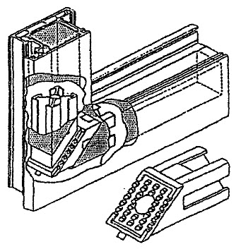
5.9.2. Impost parts are attached to adjacent PVC profiles of the frame (sash) using steel or plastic fasteners, screws or screws. Examples of fastening imposts are shown in Figure 8.
Figure 8. Examples of fastening imposts

It is allowed to use welded T-shaped and cross-shaped connections of imposts. In this case, the strength of the connections must be no lower than the strength established for corner connections.
5.9.3. Corner and T-shaped connections of profiles must be sealed. It is allowed to seal the mechanical connections of PVC profiles with weather-resistant elastic gaskets. Gaps up to 0.5 mm can be sealed with special sealants that do not impair the appearance of the products and protect the connections from moisture penetration.
5.9.4. Product designs must include a system of holes: for draining the cavity between the edges of the glass unit and the folds of the profiles; water drainage; wind pressure compensation; reducing heating of colored profiles.
5.9.5. Each glazing field must have holes for draining the cavity between the edges of the glass unit and the folds of the profiles. The holes should be located in the deepest parts of the folds and not have burrs that prevent water drainage. For systems with a middle seal, the holes must be located in front of the middle seal on the outside.
In the lower profile of the sash there must be at least two holes with a maximum distance between them of 600 mm, in the upper profile with a length of up to 1 m - two holes, and more than 1 m - three. Recommended hole sizes are at least 8 mm in diameter or at least 5 x 10 mm in size.
The location of the holes should not coincide with the installation locations for the linings under the double-glazed windows. The holes in the profile walls must be offset relative to each other by at least 50 mm.
5.9.6. The lower profiles of boxes and horizontal imposts must have at least two drainage holes measuring at least (5 x 20) mm, the distance between which should not be more than 600 mm.
The drainage holes must be offset in the profile walls by at least 50 mm. The holes must not have burrs that would impede water drainage.
For systems with a middle seal, the slots must be located in front of the middle seal on the outside.
The holes on the front surface of the box should be protected with decorative visors.
5.9.7. For systems with external and internal seals and for systems with three sealing circuits, when installing products at a height of more than 20 m, it is recommended to make holes in the upper horizontal profiles of the frames to compensate for wind pressure in the cavity between the frame and the sash.
The holes for compensating wind pressure must have a diameter of at least 6 mm or a size of at least (5 x 10) mm in the upper profile of the box. If the length of the box profile is up to 1 m, two holes are drilled, and more than 1 m - three.
To compensate for wind pressure, it is allowed to remove the outer seal in sections of 30 mm in length in the upper profile of the box.
5.9.8. Functional openings should not pass through the walls of the main chambers of the profiles.
5.9.9. In the case of using colored profiles, it is recommended (for ventilation of external chambers to avoid overheating when exposed to sunlight) to make through holes through the walls of the external chambers of the profiles of sashes and frames with a diameter of 5 - 6 mm.
5.9.10. The number and location of all types of holes are established in the working documentation. In this case, the influence of drainage holes on adjacent functions of products (sound, heat insulation, etc.) should be taken into account.
5.9.11. The depth of pinching of a double-glazed window (glass) in the folds of profiles, as well as the depth of pinching by glazing beads, should not be less than 14 mm.
Completeness
5.10.1. The complete set of products when delivered to the consumer must meet the requirements established in the order.
5.10.2. Finished products must have installed devices, double-glazed windows, sealing gaskets and a protective film on the front surfaces. A set of products may include additional, connecting and other profiles for various purposes in accordance with GOST 30673.
Component profiles, parts of locking devices protruding beyond the plane of the product, as well as decorative visors may be supplied unmounted with the products.
By agreement between the manufacturer and the consumer, separate transportation of double-glazed windows is allowed, and the consumer must be provided with a diagram for installing linings under the double-glazed windows.
5.10.3. The delivery package must include a quality document (passport) and instructions for use of the products.
5.10.4. At the consumer's request, the manufacturer provides him with standard instructions for installing window units, and also completes the product with materials for caring for the product in accordance with the requirements of the operating instructions.
Marking
5.11.1. Product marking is in accordance with GOST 23166.
5.11.2. The main profiles, window fittings and double-glazed windows included in the product must be marked in accordance with the ND for these products.
Acceptance rules
6.1. Products must be accepted by the technical control of the manufacturer for compliance with the requirements of this standard, as well as the conditions specified in the contract for the manufacture and supply of products.
Confirmation of acceptance of products by technical control of the manufacturer is their marking, as well as the execution of documents on acceptance and quality of products.
Products are accepted in batches. When accepting products at the manufacturing enterprise, the number of products manufactured within one shift and issued with one quality document is taken as a batch.
6.2. The product quality requirements established in this standard confirm:
incoming inspection of materials and components;
operational production control;
acceptance control of finished products;
control acceptance tests of a batch of products carried out by the quality service of the manufacturer;
periodic testing of products in independent testing centers;
qualification and certification tests.
6.3. The procedure for conducting incoming inspection and operational production control at workplaces is established in the technological documentation.
If the manufacturer completes window units with components of its own manufacture, they must be accepted and tested in accordance with the requirements of the regulatory documentation for these products.
6.4. Acceptance quality control of finished products is carried out individually, using the method of continuous control. In this case they check:
appearance of products;
deviations in the size of gaps under the overlay;
sagging of opening elements;
deviation in the size of the distance between the flaps of the valves;
presence and location of holes;
operation of window devices and hinges;
the presence of a protective film on the front surfaces.
Finished products that have passed acceptance control are marked. Products that do not pass acceptance control for at least one indicator are rejected.
6.5. Products must undergo control acceptance tests carried out by the quality service of the manufacturer at least once per shift. At the same time, they control:
deviations of nominal dimensions and straightness of edges;
strength of corner joints;
requirements for installing linings under double-glazed windows;
requirements for installation of sealing gaskets;
requirements for installation of reinforcing liners;
location and operation of window fixtures;
requirements for the quality of welds;
requirements for appearance and presence of protective film;
requirements for the size, number and location of functional holes;
requirements for labeling and packaging.
Tests are carried out on three samples.
In the case of a negative test result for at least one indicator, the quality of products is re-checked on twice the number of samples for the indicator that had a negative test result. If a non-compliance of the indicator with the established requirements is detected again, the controlled and subsequent batches of products are subjected to continuous control (grading). If the result of continuous control is positive, they return to the established procedure for acceptance tests.
In case of a negative test result in terms of the strength of corner joints, repeated tests are carried out on twice the number of samples. If the result of repeated tests is unsatisfactory, the batch is rejected, and production of the products is stopped until the cause of the defect is eliminated.
6.6. Periodic tests on the performance indicators specified in 5.3.1 - 5.3.3 are carried out when changes are made to the design of products or their manufacturing technology, but at least once every five years, as well as during certification of products (in terms of indicators provided for by certification methods ).
Qualification tests of products are carried out when products are put into production. In justified cases, it is allowed to combine qualification and certification tests.
Tests are carried out in independent testing centers,
accredited to conduct them.
6.7. The consumer has the right to carry out quality control checks of products, while observing the sampling procedure and test methods specified in this standard.
When accepting products by the consumer, a batch is considered to be the number of products shipped according to a specific order, but not more than 500 pieces, documented in one quality document.
Table 3

By agreement of the parties, acceptance of products by the consumer can be carried out at the manufacturer's warehouse, at the consumer's warehouse or in another place specified in the supply agreement.
6.9. Each batch of products must be accompanied by a quality document (passport) in accordance with GOST 23166.
6.10. Acceptance of products by the consumer does not relieve the manufacturer from liability if hidden defects are discovered that lead to a violation of the performance characteristics of the products during the warranty period.
Control methods
7.1. Methods of incoming and production operational quality control are established in the technological documentation.
7.2. Control methods for acceptance inspection and acceptance testing
7.2.1. The geometric dimensions of products, as well as the straightness of the edges, are determined using the methods established in GOST 26433.0 and GOST 26433.1.
Maximum deviations from the nominal dimensions of product elements, the difference in diagonal lengths and other dimensions are determined using a metal measuring tape in accordance with GOST 7502, calipers in accordance with GOST 166, probes in accordance with ND.
Maximum deviations from the straightness of the edges are determined by applying a straight edge in accordance with GOST 8026 or a building level with a flatness tolerance of at least the ninth degree of accuracy in accordance with GOST 9416 to the tested part and measuring the largest gap using feeler gauges according to ND.
Measurements of linear dimensions should be made at the air temperature of the products (20 +/- 4) °C. If it is necessary to carry out measurements at other temperatures, the temperature change in the linear dimensions of the profiles should be taken into account: 0.8 mm/m for every 10 °C deviation from the specified temperature.
7.2.2. The maximum deviations of the nominal dimensions of the gaps under the overlay are checked using a set of feeler gauges. The gaps in the rebate are determined with a caliper by measuring adjacent cross-sectional dimensions.
7.2.3. The sag in the mating of adjacent parts is determined with a feeler gauge as the distance from the edge of a metal ruler according to GOST 427, applied to the upper mating surface, to the lower surface.
7.2.4. The appearance and color of products (including in places of welds) are assessed by comparison with standard samples approved in the prescribed manner.
Differences in color, gloss and surface defects visible to the naked eye from a distance of (0.6 - 0.8) m in natural light of at least 300 lux are not allowed.
7.2.5. The tight fit and correct installation of sealing gaskets, the presence and location of pads, functional holes, window fittings, fasteners and other parts, the color and absence of cracks in welded joints, the presence of a protective film, markings and packaging are checked visually. To determine the tightness of the sealing gaskets, compare the dimensions of the gaps in the recesses and the degree of compression of the gaskets, which should be at least 1/5 of the height of the uncompressed gasket. Measurements are made with a caliper.
The tightness of the sealing gaskets in closed casement vestibules can be determined by the presence of a continuous trace left by a coloring agent (for example, colored chalk) previously applied to the surface of the gaskets and easily removed after inspection.
7.2.6. Determination of strength (bearing capacity) of fillet welded joints
To test the strength of fillet welded joints, the load application diagrams shown in Figure 9 are used.
Figure 9. Schemes for applying loads when determining the strength of fillet welded joints

The test procedure is in accordance with GOST 30673 with the following additions.
Weld seams are cleaned according to the accepted technology for manufacturing window blocks.
Samples are tested with reinforcing inserts inserted into them.
The magnitude of the loads is taken according to 5.3.3, the control method is non-destructive, exposure under load is at least 3 minutes.
The test result is considered satisfactory if each sample withstood the load without destruction or cracking.
7.2.7. The operation of window devices is checked by opening and closing the sash elements of the product five times. If deviations are detected in the operation of window devices, they are adjusted and rechecked.
7.3. Methods of control during periodic testing
7.3.1. The strength (bearing capacity) of fillet welded joints is determined according to 7.2.6.
When conducting tests, the use of other load patterns and test equipment is permitted. In this case, test methods, including processing of results, must be correlated with the test method in 7.2.6.
7.3.2. The reduced heat transfer resistance is determined according to GOST 26602.1.
7.3.3. Air permeability is determined according to GOST 26602.2.
7.3.4. Sound insulation is determined according to GOST 26602.3.
7.3.5. The total light transmittance is determined according to GOST 26602.4.
7.3.6. Resistance to static loads is determined according to GOST 24033.
7.3.7. Indicators of durability (including resistance to climatic and atmospheric loads), reliability of window devices, as well as the forces applied to window devices are determined according to methods approved in the prescribed manner.
Packaging, transportation and storage
8.1. Packaging of products must ensure their safety during storage, loading and unloading and transportation.
It is recommended to pack products in plastic film in accordance with GOST 10354.
8.2. Devices or parts of devices that are not installed on the products must be packaged in plastic film in accordance with GOST 10354 or in other packaging material that ensures their safety, firmly tied up and supplied complete with the products.
8.3. Opening doors of products must be closed with all locking devices before packaging and transportation.
8.4. Products are transported by all modes of transport in accordance with the rules for the carriage of goods in force for this type of transport.
8.5. When storing and transporting products, they must be protected from mechanical damage, exposure to precipitation, significant temperature fluctuations and direct sunlight.
8.6. When storing and transporting products, it is not allowed to stack them on top of each other; it is recommended to install gaskets made of elastic materials between the products.
8.7. Products are stored in a vertical position at an angle of 10 - 15° to the vertical on wooden pads, pallets or in special containers in covered areas without direct contact with heating devices.
8.8. In the case of separate transportation of double-glazed windows, the requirements for their packaging and transportation are established in accordance with GOST 24866.
manufacturer's warranty
9.1. The manufacturer guarantees that products comply with the requirements of this standard, provided that the consumer complies with the rules of transportation, storage, installation, operation, as well as the scope of application established in the regulatory and design documentation.
9.2. The guaranteed shelf life of the products is 1 year from the date of shipment of the product by the manufacturer.
9.3. The warranty service life of products is established in the supply contract, but not less than 3 years from the date of shipment of the products by the manufacturer.
Appendix A (reference)
TERMS AND DEFINITIONS
For the purposes of this standard, the following terms and corresponding definitions apply.
Profile system - a set (set) of PVC profiles and component elements, combined into a complete structural system, documented in design documentation.
Profiles are parts of window blocks made by extrusion with specified shapes and cross-sectional dimensions.
Profile width is the largest dimension between the front outer and inner surfaces of the profile.
Profile height is the largest cross-sectional dimension of the profile in the direction perpendicular to the profile width.
The chamber is a closed internal cavity (system of cavities) of a PVC profile, located perpendicular to the direction of heat flow. The chamber may consist of a number of subchambers separated by partitions. Chambers and subchambers can perform various specified functions, for example, for installing reinforcement inserts or as self-ventilation channels.
Rebate is a part of the profile surface formed by the protrusion of one of its parts.
Rebate is the distance between the sash and the frame, established based on the conditions for the normal functioning of locking window devices.
The narthex is the place where the sash connects with the frame bars (main narthex), with the impost (impost narthex) or with the sash (impostless, stulpovy narthex).
Overlap is a protrusion in the narthex assembly, formed by the protruding part of the frame (sash) and overlapping the sash (frame) by the size in the narthex under the overlay.
Reinforcing liner is a profile steel element installed in the internal chamber of the main profile to absorb operational loads.
A combination of profiles is a junction of mating profiles (for example, a frame profile - a sash profile with a glazing bead; an impost profile - a sash profile with a glazing bead; a sash profile with a bead and a glazing bead - a sash profile with a glazing bead).
The main profiles are the profiles of frames, sashes, imposts, and frames, which perform a strength function as an integral part of window and balcony door structures.
Additional profiles are profiles that do not perform a strength function as an integral part of window and balcony door structures.
Glazing beads (glass layouts) are additional profiles designed for fastening double-glazed windows.
Glazing beads can be manufactured with a co-extruded sealing gasket.
Connecting profiles (connectors) - profiles designed for interlocking window and balcony door frames with each other in structures consisting of two or more products. Connectors can connect frame profiles at different angles and are selected taking into account strength requirements.
Expansion profiles (extenders) - profiles designed to increase the height of the window frame profile.
Slabs are profiles designed for dividing the glazing fields of sashes.
Decorative overlays are overhead decorative profiles glued to a double-glazed window from the inside and outside and forming a false binding.
Flashings are profiles designed to drain water from the window structure.
Facing profiles - profiles for finishing window slopes (corners, platbands, trims, etc.). Cladding profiles can form various systems.
Controlled ventilation is the organization of ventilation of rooms with different air exchange rates due to the design solutions of products.
Self-ventilation is a system of limited air exchange through the channels of profile chambers or through climate valves built into window units in order to regulate the air humidity in the room and prevent condensation on the internal surfaces of the windows.
Durability is a characteristic of products that determines their ability to maintain performance qualities for a given period, confirmed by the results of laboratory tests and expressed in conventional years of operation (service life).
Definitions of the main parts, dimensions and functional areas of profile combinations are shown in Figures A.1 and A.2.
Figure A.1. Main details of the profile combination

Figure A.2. Main dimensions and functional areas of profile combination parts

COMPOSITION OF WORKING DOCUMENTATION FOR WINDOW AND BALCONY DOOR UNITS
Documentation for the production of window and balcony door blocks from PVC profiles must contain the following data:
B.1. Window and door blocks.
The design description must include:
methods and schemes for opening windows;
methodology for calculating basic and functional dimensions;
tables (diagrams) of the maximum permissible dimensions (proportions) of sashes;
types and sizes of reinforcement liners used depending on the sizes of sashes, frames, imposts, crossbars;
drawings of the location of holes for water drainage, drainage of glazing rebates, compensation of wind pressure, indicating their number and size;
number and location of locking devices;
additional requirements for windows made of colored profiles.
B.2. PVC profiles:
sections of profiles indicating their functions and division into main and additional profiles, profile articles;
basic and functional dimensions of profiles;
sections of profile combinations with main dimensions;
information on the physical and mechanical characteristics and durability of PVC profiles.
B.3. Reinforcing inserts:
material;
type and thickness of anti-corrosion coating;
sections with main dimensions;
moments of inertia (E x J).
B.4. Sealing gaskets:
material, dimensions, section shapes, recommended requirements.
B.5. Glazing:
table with possible combinations of double-glazed windows, sealing gaskets and glazing beads;
installation diagram for glazing pads.
B.6. Profile connections (corner, impost, etc.):
for welded joints - design strength for all main profiles;
for mechanical connections - a description of connecting parts, reinforcements, fasteners, sealing gaskets and sealants.
B.7. Window devices and hinges:
opening options;
designation of various types of window devices;
locations of devices and loops;
restrictions on the weight and size of the valves;
characteristics of protective and decorative coating;
conditions for adjusting locking devices and hinges.
B.8. Technological documentation for the manufacture of windows:
technological documentation for the manufacture of windows must include process maps, technological regulations, including quality control regulations, and other necessary documents.
B.9. Standard product installation instructions
B.10. Instructions for use of products
General requirements for installation of products are given in Appendix D.
SYSTEM OF FUNCTIONAL HOLES AND INTRA-PROFILE DUCT SELF-VENTILATION
(FIGURES B.1 - B.3)
Figure B.1. Functional hole system 
Figure B.2. Location of functional holes

Figure B.3. In-profile duct self-ventilation system
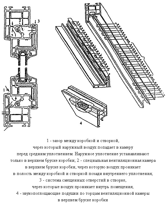
GENERAL REQUIREMENTS FOR INSTALLATION OF PRODUCTS
D.1. Requirements for the installation of products are established in the design documentation for construction projects, taking into account the design options for junctions of products to walls adopted in the project, designed for specified climatic and other loads.
D.2. Installation of products must be carried out by specialized construction companies. The completion of installation work must be confirmed by an acceptance certificate, which includes the warranty obligations of the work manufacturer.
D.3. At the request of the consumer (customer), the manufacturer (supplier) of products must provide him with standard instructions for the installation of window and balcony door units made of PVC profiles, approved by the head of the manufacturer and containing:
drawings (diagrams) of typical mounting junction units;
list of materials used (taking into account their compatibility and temperature conditions of use);
sequence of technological operations for installing window units.
D.4. When designing and executing junction units, the following conditions must be met:
The sealing of the installation gaps between the products and the slopes of the openings of wall structures must be tight, sealed along the entire perimeter of the window, designed to withstand climatic loads outside and operating conditions indoors.
A variant of the window block mounting assembly is shown in Figure D.1;
Figure D.1. Example of a window block mounting assembly

the design of the junction units (including the location of the window block along the depth of the opening) should prevent the formation of cold bridges (thermal bridges), leading to the formation of condensation on the internal surfaces of window openings;
the operational characteristics of the structures of the junction units (resistance to heat transfer, sound insulation, air and water permeability) must meet the requirements established in the building codes;
the vapor barrier of the seams on the side of the premises should be denser than on the outside;
the design of the junction units must ensure reliable drainage of rainwater and condensate to the outside. Moisture penetration into wall structures and premises is not allowed;
When choosing to fill installation gaps, operational temperature changes in the overall dimensions of products should be taken into account.
In order to increase the reliability of thermal insulation of the assembly unit, it is recommended to use window blocks with a frame width of at least 80 mm.
D.5. The following should be used as fasteners for installation of products:
flexible anchors complete with screws and dowels;
construction dowels;
mounting screws;
special mounting systems (for example, with adjustable mounting supports).
Options for mounting fasteners are presented in Figure D.2 and are selected depending on the wall design.
Figure D.2. Mounting options
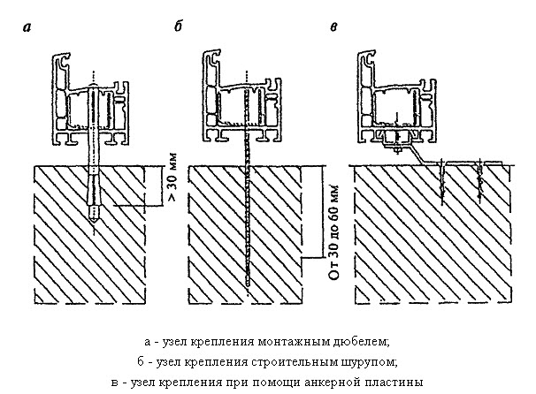
The use of sealants, adhesives, foam insulation materials, and construction nails for fastening products is not allowed.
D.6. Window units should be installed level. Deviations from the vertical and horizontal sides of the boxes of mounted products should not exceed 1.5 mm per 1 m of length, but not more than 3 mm per product height.
G.7. The distance between fasteners when installing white products with profiles reinforced with steel liners should not exceed 700 mm, in other cases - no more than 600 mm (Figure D.3).
Figure D.3. Location of fasteners
G.8. To fill installation gaps (seams), silicone sealants, pre-compressed PSUL sealing tapes (compression tapes), insulating polyurethane foam cords, foam insulation, mineral wool and other materials that have a hygienic certificate and provide the required performance characteristics of the seams are used. Foam insulation materials should not have bitumen-containing additives and increase their volume after completion of installation work.
Painting over seams is not recommended.
G.9. To transfer loads in the plane of the window (weight) of the product to the building structure, load-bearing blocks made of polymer materials with a hardness of at least 80 units are used. Shore A or hardwood. To fix the position of the window block in the wall, spacer blocks are used.
With multi-layer wall structures, when a window block is installed in the insulation zone, the loads must be transferred to the load-bearing part of the wall.
Wooden wedges used for temporary fixation of products during installation must be removed before sealing assembly seams.
G.10. In the case of assembly blocking of window blocks with each other or with balcony door blocks, the connection of products should be made through special connecting profiles, which may have reinforcing liners to increase the strength characteristics of the products. The connection must be tight, preventing blowing and penetration of moisture, compensating for the thermal expansion of products.
Options for the blocking unit for window and balcony door blocks are shown in Figure D.4.
Figure D.4. An example of a blocking unit for a window and balcony door block

G.11. Removing the protective film from the front surfaces of the profiles should be done after installing the products and finishing the installation opening, taking into account that the duration of exposure to sunlight on the protective film should not exceed ten days.
Appendix D (for reference)
INFORMATION ABOUT THE DEVELOPERS OF THE STANDARD
This standard was developed by a working group of specialists consisting of:
N.V. Shvedov, Gosstroy of Russia, head;
V.A. Tarasov, JSC "KVE-Window Technologies";
H. Scheitler, KBE GmbH;
Yu.P. Alexandrov, JSC "TsNIIPromzdanii";
T.V. Vlasova, CS of window and door technology;