For a centrifugal fan, the outlet (volute) has a constant width B, significantly exceeding the width of the impeller.
38. The width of the cochlea is chosen constructively:
IN»2 b 1 =526 mm.
The outline of the outlet most often corresponds to a logarithmic spiral. Its construction is carried out approximately according to the rule of the design square. In this case, the side of the square a four times less opening of the spiral casing A.
39. Size A determined from the relation:
Where average speed gas leaving the cochlea WITH and is found from the relation:
WITH a =(0.6¸0.75)* WITH 2u=33.88 m/s.
A = A/4 =79,5 mm.
41. Let's determine the radii of the arcs of circles forming a spiral. The starting circle for the formation of a cochlear spiral is the circle of radius:
![]() , mm.
, mm.
Cochlea opening radii R 1 , R 2 , R 3 , R 4 is found using the formulas:
R 1 = R H + =679.5+79.5/2=719.25 mm;
R 2 = R 1 + A=798.75 mm;
R 3 = R 2 + a=878.25 mm;
R 4 = R 3 + A=957.75 mm.
The construction of the cochlea is carried out in accordance with Fig. 4.

Rice. 4. Profiling the fan volute using the design square method
Near the impeller, the outlet turns into a so-called tongue, which separates the flows and reduces leakage inside the outlet. The part of the outlet limited by the tongue is called the outlet part of the fan housing. Outlet length C determines the area of the fan outlet. The outlet part of the fan is a continuation of the exhaust and performs the functions of a curved diffuser and a pressure pipe.
Built-in fan mounted on a shaft electric machine, must create a pressure sufficient to ensure required consumption cooling medium in the ducts of the machine's ventilation system. Fans are designed taking into account the design features of a specific type of machine.
Below is a simplified method for calculating the built-in fan, based on data from serial machines general purpose. In such machines, centrifugal fans with radial blades are mainly used, Working wheel which changes its flow direction to radial.
The outer diameter of the fan wheel is selected in accordance with the type of ventilation system and machine design. With axial ventilation, the outer diameter of the impeller (Fig. 7.7) is chosen as large as possible.

Rice. 7.7. Fan wheel
Based on the selected outer diameter of the fan, the peripheral speed is determined, m/s:
 .
(7.49)
.
(7.49)
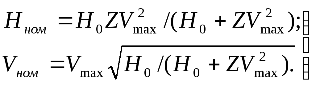
The maximum fan efficiency value approximately corresponds to the mode when the nominal fan pressure  ,Where
  -
the pressure developed by the fan in idle mode, i.e., with the outer diameter holes closed, when the air flow is zero. The nominal flow rate is approximately:
-
the pressure developed by the fan in idle mode, i.e., with the outer diameter holes closed, when the air flow is zero. The nominal flow rate is approximately:
 ,
,
Where  - fan flow rate, m 3 /s, operating in short circuit mode (by analogy with an electrical circuit), i.e. in open space.
From the condition of maximum efficiency it is accepted
 .
(7.50)
.
(7.50)
Section at the fan outlet edge, m2,
 ,
(7.51)
,
(7.51)
where 0.42 is the nominal efficiency of the radial fan.
Fan wheel width
 ,
(7.52)
,
(7.52)
where 0.92 is a coefficient that takes into account the presence of ventilation blades on the surface of the ventilation grille (surface  ).
).
Wheel inner diameter  determined from the condition that the fan operates at the maximum efficiency value, i.e. at
  And
And  . Using the equations for the static pressure developed by the fan, Pa, we find the pressure developed by the fan at idling:
 ,
(7.53)
,
(7.53)
Where  =
0.6 for radial blades;
=
0.6 for radial blades;  kg/m 3 - air density.
Knowing the air flow V,
resistance ventilation system
 and determining the peripheral speed at the inner edge of the fan:
 ,
(7.54)
,
(7.54)
find the inner diameter of the fan wheel, m:
 .
(7.55)
.
(7.55)
In built-in fans the ratio  lies within 1.2...1.5.
The number of fan blades is:
 .
(7.56)
.
(7.56)
To reduce ventilation noise, it is recommended to select the number of fan blades so that it is an odd number. For exhaust ventilation, numbers depending on the diameter of the fan can also be recommended: when  mm
mm  , at
, at  mm
mm  , at
, at  mm
mm  , at
, at  mm
mm  .
.
For fans of asynchronous motors of the 4A series, it is recommended to select the number of blades according to table. 7.6.
Table 7.6. Number of fan blades
|
Rotation axis height, mm |
Number of blades at |
|
|
|
|
|


The number of fan blades for DC machines is selected approximately:
 .
(7.57)
.
(7.57)
Meaning  round to the nearest prime number.
After calculating the fan, it is necessary to clarify the results of the ventilation calculation.
To determine the actual air flow  and pressure
  and build the combined characteristics of the fan and the ventilation tract of the machine. The fan characteristic can be expressed with sufficient accuracy by the equation
Characteristics of the ventilation tract according to (7.50)
 .
(7.59)
.
(7.59)
In Fig. 7.8 shows graphs constructed using equations (7.58) (curve 1 ) and (7.59) (curve 2 ). The coordinate of the intersection point of these characteristics is determined by solving the equations
 (7.60)

Rice. 7.8. Fan characteristics
Power consumed by the fan, W,
 ,
(7.61)
,
(7.61)
Where  - energy efficiency of the fan, which can be taken equal to approximately
 (7.62)
The ventilation calculation of an electric machine during course design is carried out using a simplified method. More detailed calculations of individual types of machine designs are given in Chapter. 9-11.
Snail fans get their name from the shape of the body, which resembles the shell of this mollusk. Today this type of equipment is used both in industry and in residential construction in ventilation systems. Manufacturers today offer several models of snails for ventilation. But they all work on the same principle - the centrifugal force created by the rotation of the blades on the rotor captures air through the snail-shaped inlet and pushes it through a straight outlet located at 90° in a different plane to the inlet.
General information about centrifugal (radial) fans
Coil fans have a dual designation (marking): VR and VC, that is, radial and centrifugal. The first indicates that the blades of the working part of the equipment are located radially relative to their rotor. The second is the designation of the physical principle of operation of the device, that is, the process of taking and moving air masses occurs due to centrifugal force.
It is centrifugal fans in ventilation systems that have proven themselves to be positive side due to high efficiency of air removal.
Operating principle
As already mentioned, fans of this modification operate based on the action of centrifugal force.
- The blades attached to the rotor of the device rotate with high speed, creating turbulence inside the housing.
- The inlet pressure drops, which causes the suction of nearby air, which rushes inward.
- Under the action of the blades, it is thrown to the periphery of the space, where high pressure is created.
- Under its action, the air flow rushes to the outlet pipe.
This is how all centrifugal models work, which are installed not only in ventilation systems, but also in smoke removal systems. About the latter, it must be said that their body is made from aluminum alloy or steel coated with heat-resistant materials, and are equipped with an explosion-proof electric motor.
Design Features
As already mentioned, the main design feature is the snail. It is also necessary to indicate the shape of the blades. Fans of this brand use three types:
- with straight slope,
- with a backward tilt
- in the form of a wing.
The first position is small fans with high power and productivity. That is, they can create conditions in which other models require a large body. At the same time they work with low level noise. The second position is economical option, which consumes 20% less electricity than other positions. Such fans can easily withstand loads.
As for the design that relates to the electric motor, there are also three positions:
- the rotor is fixed directly to the motor shaft through a coupling and bearings;
- through a belt drive using pulleys;
- The impeller is mounted on the electric motor shaft.
And one more feature is the connection points between the fan and the air ducts of the ventilation system. The inlet pipe has rectangular shape holes, exit round.
Kinds
Types of centrifugal fans of snails are three positions, differing from each other in power. This parameter depends on the rotation speed of the electric motor, and therefore the rotor, as well as on the number of blades in the device design. Here are three types:
- Snail fans low pressure, the parameter of which does not exceed 100 kg/cm². Most often they are used in ventilation systems apartment buildings. Install snails on roofs.
- Medium pressure models – 100-300 kg/cm². Installed in ventilation systems of industrial facilities.
- Variety high pressure– 300-1200 kg/cm². These are powerful fan units, which are usually included in the air exhaust system of paint shops, in industries where pneumatic transport is installed, in warehouses with fuels and lubricants and other premises.
There is another division of snail fans - according to their purpose. These are primarily general purpose devices. Then there are three more positions: explosion-proof, heat-resistant and corrosion-resistant.
Restrictions on use
- with sticky suspensions with a concentration of more than 10 mg/m³;
- With fibrous materials in the air;
- with explosive inclusions;
- with corrosive particles;
- and in warehouses where explosives are stored.
In all other cases, snails can be used without restrictions. And one more point regulating the conditions of their operation is temperature regime which must not be violated: from -45C to +45C.
Popular models
In principle, there is no model division of snails. There are certain brands that are produced by all manufacturers. And they are divided mainly according to their intended purpose. For example, a VRP fan, where the letter “P” means that this is a dust model, which is used in ventilation and aspiration systems to remove air with a high concentration of dust. That is, this is a specific model that must be used for its intended purpose. Of course, this device can easily handle ordinary air, but it is more expensive than standard VR or VC, because its design uses thick metal to make the body and blades, hence the higher power of the electric motor.
The same applies to VR DU brand fans, that is, for smoke removal. They are made from more quality materials with installation of an explosion-proof motor. Hence their high price. As for other positions, VR is divided into types that have already been mentioned, and each group has its own models with its own technical characteristics.
How to make it yourself
The question posed by the title of this section can be classified as rhetorical. That is, in principle, you can make a snail with your own hands if you have the skills of a tinsmith or welder. Because the device will have to be assembled from sheet metal. And depending on the power and performance of the device, the metal will have different thicknesses.
Plus, making the blades yourself and attaching them to the rotor properly is difficult. Because the rotor will rotate at enormous speed, and if the balancing of the structure is upset, the fan will be torn apart in the first 20 seconds of operation. Yes, and you need to choose the right electric motor, taking into account the power and rotation speed, plus correctly connect it to the fan rotor. So don’t try to do anything with your own hands - it’s dangerous for your own life.
The so-called snail for ventilation may not always mean the same type of forcing ventilation device- basic common features, this is the form of the unit, but by no means the principle of operation and direction of the air flow.
Injection devices of this type can:
- radically different in the design of the blades;
- and can also be of supply or exhaust type, that is, direct the flow in the opposite direction.
Ventilation snail
They are usually used for solid fuel boilers big size, production workshops And public buildings, but about all this below, and in addition - a video in this article.
Mechanical ventilation
Note. Blower/suction units with an electric motor, which are called “snails,” are not suitable for any type of ventilation, since they can only direct the air flow in one direction.
Types of ventilation

- As you can see in the top image, the word “ventilation” can mean completely different ways air exchange and some you may not have even heard of, but we will briefly consider only the most basic of them.
- Firstly, there is a well-known exhaust method, when warm or polluted air is removed from the room.
- Secondly, there is a supply option and most often this is the addition of fresh cool air.
- Thirdly, this is a combination, that is, a supply and exhaust option.
- The above systems can function naturally, but can also be forced using axial (axial), radial (centrifugal), diametrical (tangential) and diagonal fans. In addition, exhaust and air supply can be carried out either in general or in local mode. That is, the air duct is supplied to a specific destination and performs the function of blowing or exhaust.
Examples
Note. Below we will look at several types of snails that are used for.

BDRS 120-60 (Türkiye) is exhaust snail radial type with a weight of 2.1 kg, a frequency of 2325 rpm, a voltage of 220/230V/50Hz and a maximum power consumption of 90W. At the same time, BDRS 120-60 is able to pump a maximum of 380 m 3 /min of air with a temperature range from -15⁰C to +40⁰C, and has a safety class of IP54.
The BDRS brand can have several standard sizes; the external rotary motor is made of galvanized steel and is protected on the side by a chrome grille, which prevents foreign elements from getting onto the impeller.
Heat-resistant supply and exhaust radial fan Dundar CM 16.2H is usually used for pumping hot air from boilers operating on solid fuel, although the instructions allow it to also be used indoors for various purposes. The air flow during transportation can have a temperature from -30⁰C to +120⁰C, and the snail itself can be rotated to 0⁰ (horizontal position), 90⁰, 180⁰ and 270⁰ (motor on the right side).
The CM 16.2H model has a motor speed of 2750 rpm, a voltage of 220/230V/50Hz and a maximum power consumption of 460W. The unit weighs 7.9 kg and is capable of pumping a maximum volume of 1765 m 3 /min of air, a pressure level of 780 Pa, and has a protection degree of IP54.

Various modifications of VENTS VSCHUN can be used for the needs and air conditioning of premises for various purposes and have an air transportation capacity of up to 19000 m 3 /hour.
Such centrifugal scroll It has a spiral-rotary housing and an impeller, which is mounted on the axis of a three-phase asynchronous motor. The VSCHUN body is made of steel, which is later coated with polymers
Any modification implies the ability to rotate the body to the right or left. This allows you to connect to existing air ducts at any angle, but the step between the fixed position is 45⁰.
Also on different models Either two-stroke or four-stroke can be used asynchronous motors with an external rotor arrangement, and its impeller in the form of forward-curved blades is made of galvanized steel. Rolling bearings increase the operating life of the unit, factory-balanced turbines significantly reduce noise, and the protection level is IP54.

In addition, for VSCHUN it is possible to adjust the speed yourself using an autotransformer regulator, which is very convenient when:
- change of seasons;
- working conditions;
- premises and so on.
In addition, several units of this type can be connected to an autotransformer device at once, but at the same time mandatory the main condition must be met - their total power should not exceed the rating of the transformer.
| Specifying a parameter | VTsUN | |||||||
| 140×74-0.25-2 | 140×74-0.37-2 | 160×74-0.55-2 | 160×74-0.75-2 | 180×74-0.56-4 | 180×74-1,1-2 | 200×93-0.55-4 | 200×93-1,1-2 | |
| Voltage (V) at 50Hz | 400 | 400 | 400 | 400 | 400 | 400 | 400 | 400 |
| Power consumption (kW) | 0,25 | 0,37 | 0,55 | 0,75 | 0,55 | 1,1 | 0,55 | 1,1 |
| Current)A) | 0,8 | 0,9 | 1,6 | 1,8 | 1,6 | 2,6 | 1,6 | 2,6 |
| Air flow maximum (m 3 /hour) | 450 | 710 | 750 | 1540 | 1030 | 1950 | 1615 | 1900 |
| Rotation speed (rpm) | 1350 | 2730 | 1360 | 2820 | 1360 | 2800 | 1360 | 2800 |
| Sound level at 3m (db) | 60 | 65 | 62 | 68 | 64 | 70 | 67 | 73 |
| Air temperature during transportation maximum t⁰C | 60 | 60 | 60 | 60 | 60 | 60 | 60 | 60 |
| Protection | IP54 | IP54 | IP54 | IP54 | IP54 | IP54 | IP54 | IP54 |
Brief characteristics of centrifugal fans
Centrifugal fans belong to the category of blowers with the greatest variety of design types. Fan wheels can have blades curved both forward and backward relative to the direction of rotation of the wheel. Fans with radial blades are quite common.
When designing, it should be taken into account that fans with backward blades are more economical and less noisy.
The fan efficiency increases with increasing speed and for conical wheels with backward blades can reach a value of 0.9.
Taking into account modern requirements To achieve energy saving when designing fan installations, one should focus on fan designs that correspond to the proven aerodynamic designs Ts4-76, 0.55-40 and similar to them.
Layout solutions determine the efficiency of the fan installation. With a monoblock design (wheel on an electric drive shaft), the efficiency has the maximum value. The use of a running gear in the design (a wheel on its own shaft in bearings) reduces the efficiency by approximately 2%. V-belt drive Compared to the clutch, it further reduces the efficiency by at least another 3%. Design decisions depend on fan pressure and speed.
According to the developed excess pressure General purpose air fans are divided into the following groups:
1. high pressure fans (up to 1 kPa);
2. medium pressure fans (13 kPa);
3. low pressure fans (312 kPa).
Some specialized high-pressure fans can reach pressures of up to 20 kPa.
Based on speed (specific speed), general-purpose fans are divided into the following categories:
1. high-speed fans (11 n s 30);
2. medium speed fans (30 n s 60);
3. high-speed fans (60 n s 80).
Design solutions depend on the flow required by the design task. For large flows, fans have double-suction wheels.
The proposed calculation belongs to the constructive category and is performed by the method of successive approximations.
Coefficients of local resistance of the flow part, coefficients of change in speed and ratios linear dimensions are set depending on the design pressure of the fan with subsequent verification. The criterion for the correct choice is that the calculated fan pressure corresponds to the specified value.
Aerodynamic calculation of a centrifugal fan
For calculation the following are specified:
1. Ratio of impeller diameters
2. The ratio of the diameters of the impeller at the gas outlet and inlet:
Lower values are selected for high pressure fans.
3. Head loss coefficients:
a) at the entrance to the impeller:
b) on the impeller blades:
c) when turning the flow onto the working blades:
d) in a spiral outlet (casing):
Smaller values of in, lop, pov, k correspond to low-pressure fans.
4. Speed change coefficients are selected:
a) in a spiral outlet (casing)
b) at the entrance to the impeller
c) in working channels

5. The head loss coefficient is calculated, reduced to the flow velocity behind the impeller:
6. From the condition of minimum pressure loss in the fan, the coefficient Rв is determined:

7. The flow angle at the impeller inlet is found:

8. The speed ratio is calculated
9. The theoretical head coefficient is determined from the condition of the maximum hydraulic coefficient useful action fan:

10. The value of hydraulic efficiency is found. fan:

11. The angle of flow exit from the impeller is determined at the optimal value of G:

hail .
12. Required peripheral speed of the wheel at the gas outlet:

M/s .
where [kg/m3] is the air density under suction conditions.
13. Determined required number revolutions of the impeller in the presence of a smooth gas entry into the impeller

RPM .
Here 0 =0.91.0 is the coefficient of filling the section with the active flow. As a first approximation, it can be taken equal to 1.0.
The operating speed of the drive motor is taken from a number of frequency values typical for electric fan drives: 2900; 1450; 960; 725.
14. Outside diameter impeller:
15. Impeller inlet diameter:
If the actual ratio of impeller diameters is close to that previously accepted, then no adjustments are made to the calculation. If the value is greater than 1m, then a fan with double-sided suction should be calculated. In this case, half the feed of 0.5 should be substituted into the formulas Q.
Elements of the velocity triangle when gas enters the rotor blades
16. The peripheral speed of the wheel at the gas inlet is found
M/s .
17. Gas speed at the impeller inlet:
M/s .
Speed WITH 0 should not exceed 50 m/s.
18. Gas speed in front of the impeller blades:
M/s .
19. Radial projection of the gas velocity at the entrance to the impeller blades:
M/s .
20. The projection of the input flow velocity onto the direction of the peripheral velocity is taken equal to zero to ensure maximum pressure:
WITH 1u = 0.
Because the WITH 1r= 0, then 1 = 90 0, that is, the gas inlet to the rotor blades is radial.
21. Relative speed of gas entry to the rotor blades:
Based on calculated values WITH 1 , U 1 , 1 , 1 , 1 a triangle of velocities is constructed as gas enters the rotor blades. With the correct calculation of speeds and angles, the triangle should close.
Elements of the velocity triangle when gas exits from the rotor blades
22. Radial projection of the flow velocity behind the impeller:

M/s .
23. Projection of the absolute gas exit velocity onto the direction of the peripheral velocity on the impeller rim:
24. Absolute gas speed behind the impeller:
M/s .
25. Relative speed of gas exit from the rotor blades:
Based on the obtained values WITH 2 , WITH 2u ,U 2, 2, 2, a velocity triangle is constructed as gas exits the impeller. With the correct calculation of speeds and angles, the speed triangle should also close.
26. Using the Euler equation, the pressure created by the fan is checked:
The calculated pressure must match the design value.
27. Width of the blades at the gas inlet into the impeller:
here: UT = 0.020.03 - coefficient of gas leakage through the gap between the wheel and the inlet pipe; u1 = 0.91.0 - filling factor of the input section of the working channels with the active flow.
28. Width of the blades at the gas outlet from the impeller:
where u2 = 0.91.0 is the active flow filling factor of the output section of the working channels.
Determination of installation angles and number of impeller blades
29. Angle of installation of the blade at the flow inlet into the wheel:
Where i- angle of attack, the optimal values of which lie within -3+5 0.
30. Angle of installation of the blade at the gas outlet from the impeller:
where is the flow lag angle due to flow deflection in the oblique section of the interscapular channel. Optimal values are usually taken from the interval at = 24 0 .
31. Average blade installation angle:
32. Number of working blades:
Round the number of blades to an even number.
33. The previously accepted flow lag angle is clarified according to the formula:
Where k= 1.52.0 with backward curved shoulder blades;
k= 3.0 with radial blades;
k= 3.04.0 with forward-curved blades;

The adjusted angle value should be close to the preset value. Otherwise, you should set a new value u.
Determination of fan shaft power
34. Total fan efficiency: 78.80
where mech = 0.90.98 - mechanical efficiency. fan;
0.02 - the amount of gas leaks;
d = 0.02 - coefficient of power loss due to friction of the impeller on the gas (disc friction).
35. Required power on the motor shaft:

25,35 kW.
Profiling of impeller blades
The most commonly used blades are those outlined in a circular arc.
36. Wheel blade radius:

37. We find the radius of centers using the formula:

R c =, m.

The blade profile can also be constructed in accordance with Fig. 3.
Rice. 3. Profiling fan impeller blades
Calculation and profiling of a spiral outlet
For a centrifugal fan, the outlet (volute) has a constant width B, significantly exceeding the width of the impeller.
38. The width of the cochlea is chosen constructively:
IN 2b 1 =526 mm.
The outline of the outlet most often corresponds to a logarithmic spiral. Its construction is carried out approximately according to the rule of the design square. In this case, the side of the square a four times less opening of the spiral casing A.
39. The value of A is determined from the relationship:
where is the average gas velocity at the exit from the cochlea WITH and is found from the relation:
WITH a =(0.60.75)* WITH 2u=33.88 m/s.
A = A/4 =79,5 mm.
41. Let's determine the radii of the arcs of circles forming a spiral. The starting circle for the formation of a cochlear spiral is the circle of radius:

Cochlea opening radii R 1 , R 2 , R 3 , R 4 is found using the formulas:
R 1 = R H +=679.5+79.5/2=719.25 mm;
R 2 = R 1 + A=798.75 mm;
R 3 = R 2 + a=878.25 mm;
R 4 = R 3 + A=957.75 mm.
The construction of the cochlea is carried out in accordance with Fig. 4.

Rice. 4.
Near the impeller, the outlet turns into a so-called tongue, which separates the flows and reduces leakage inside the outlet. The part of the outlet limited by the tongue is called the outlet part of the fan housing. Outlet length C determines the area of the fan outlet. The outlet part of the fan is a continuation of the exhaust and performs the functions of a curved diffuser and a pressure pipe.
The position of the wheel in the spiral outlet is set based on the minimum hydraulic losses. To reduce losses from disk friction, the wheel is shifted to the rear wall of the outlet. The gap between the main wheel disk and the rear outlet wall (drive side) on the one hand, and the wheel and tongue on the other, is determined by the aerodynamic design of the fan. So, for example, for the Ts4-70 scheme they are 4 and 6.25%, respectively.
Profiling the suction pipe
The optimal shape of the suction pipe corresponds to the tapering sections along the gas flow. Narrowing the flow increases its uniformity and promotes acceleration when entering the impeller blades, which reduces losses from the impact of the flow on the edges of the blades. Best performance has a smooth confuser. The interface of the confuser with the wheel should ensure a minimum of gas leaks from the discharge to the suction. The amount of leakage is determined by the gap between the outlet part of the confuser and the entrance to the wheel. From this point of view, the gap should be minimal; its real value should depend only on the magnitude of the possible radial runout of the rotor. Thus, for the aerodynamic design of the Ts4-70, the gap size is 1% of the outer diameter of the wheel.
The smooth confuser has the best performance. However, in most cases, a regular straight confuser is sufficient. The inlet diameter of the confuser must be 1.32.0 times greater than the diameter of the suction hole of the wheel.