Hello, dear reader! Today's article is about creating a simple home security system using readily available components. It's small and cheap device will help you protect your home from intrusion using Arduino, motion sensor, display and speaker. The device can be powered by a battery or a computer’s USB port.
So, let's begin!
How does it work?
The bodies of warm-blooded animals emit infrared radiation, which is invisible to human eyes, but can be detected using sensors. Such sensors are made of a material that can spontaneously polarize when exposed to heat, making it possible to detect the appearance of heat sources within the range of the sensor.
For a wider range, Fresnel lenses are used, which collect infrared radiation from different directions and concentrate it on the sensor itself.
The figure shows how the lens distorts the rays that fall on it.
It is worth noting that robots without particularly hot parts and cold-blooded ones emit very little infrared radiation, so the sensor may not work if Boston Dynamics employees or reptilians decide to surround you.
When there is a change in the level of IR radiation in the range, this will be processed on the Arduino, after which the status will be displayed on the LCD display, the LED will blink, and the speaker will beep.
What do we need?
- (or any other board).
- (16 characters on two lines)
- One connector for connecting the crown to Arduino
- (although you can use a regular speaker)
- USB cable - for programming only ( approx. translation: It always comes with our Arduino!)
- Computer (again, only for writing and loading the program).
By the way, if you don’t want to buy all these parts separately, we recommend that you pay attention to ours. For example, everything you need and even more is in our starter kit.
Let's connect!
Connecting a motion sensor is very simple:
- We connect the Vcc pin to 5V Arduino.
- We connect the Gnd pin to GND of the Arduino.
- We connect the OUT pin to digital pin No. 7 from Arduino

Now let's connect the LED and speaker. It's just as simple here:
- We connect the short leg (minus) of the LED to ground
- We connect the long leg (plus) of the LED to output No. 13 of the Arduino
- Red speaker wire to output No. 10
- Black wire - to ground

And now the hard part is connecting the 1602 LCD display to the Arduino. We have a display without I2C, so we will need a lot of Arduino outputs, but the result will be worth it. The diagram is presented below:

We only need part of the circuit (we will not have contrast adjustment with a potentiometer). Therefore, you only need to do the following:
Now you know how to connect a 1602 display to the Arduino UNO R3 (as well as to any version of Arduino from Mini to Mega).

Programming
It's time to move on to programming. Below is the code that you just need to fill in and, if you have assembled everything correctly, the device is ready!
#include
To protect your home from uninvited guests, everything more people install alarms. They allow timely warning of intrusion into the premises. Today there are Various types alarms, but in Lately The popularity of GSM alarms has begun to grow, since they allow you to receive information about intrusion at any distance from an object, the main thing is that the owner has a phone with him at the time, and this phone is online. Unfortunately, these systems are not yet too cheap to give preference exclusively to them. But nowadays you can make a simple GSM alarm yourself. And the popular Arduino board will help in this matter.
This project is a security (alarm) system to notify of intruders entering the house. The system uses GSM technology.
An intrusion detection module is connected to the microcontroller board of this security system, which can be based, for example, on an IR sensor or an ultrasonic proximity sensor. When a signal is received from such a module, an SMS message is sent to the user’s phone indicating that their home has been broken into.
The figure below shows a block diagram of the security system.
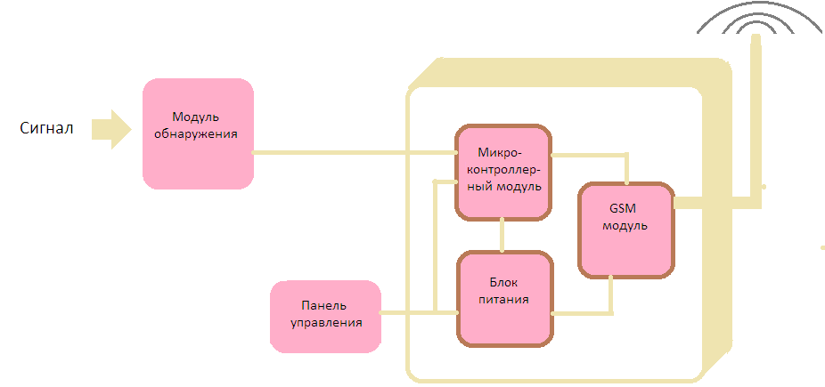
The main elements of the system are a microcontroller board (for example, Arduino Uno) and GSM module/GPRS SIM900A. The entire system can be powered from a single 12V/2A power supply.
The image below shows circuit diagram home security system with GSM based on Arduino.

The operation of the system is very simple and does not require much explanation. When the power supply is applied, the system goes into standby mode. However, when J2 is short-circuited, a warning message is automatically transmitted to a preset mobile phone number. Any detection sensor can be connected to the J2 input connector. It should be noted that low level on pin 1 of connector J2 is active and turns on the security system.
In addition, the system has added the ability to make a call by pressing the S2 button. Using the S3 button you can reset this call.
Below is the code for Arduino.
//Connect the Tx pin to pin D3 of the GPS module //Connect the Rx pin to pin D4 of the GPS module //connect the SMS sending signal to pin D7 (active level low) //Connect the CALL signal to pin D8 (active level low) //Connect the call reset signal END to pin D9 (active level low) #include
Thus, you can quite easily create a GSM alarm system based on the Arduino board with your own hands. Such an alarm system, in terms of its cost, will certainly be cheaper than branded analogues on the market today, and it will function in an almost identical way.
Infrared (IR) sensors are typically used to measure distances, but they can also be used to detect objects. By connecting several IR sensors to Arduino, we can create a security alarm.
Review
Infrared (IR) sensors are typically used to measure distances, but they can also be used to detect objects. IR sensors consist of an infrared transmitter and an infrared receiver. The transmitter emits pulses infrared radiation while the receiver detects any reflections. If the receiver detects a reflection, it means that there is some object at some distance in front of the sensor. If there is no reflection, there is no object.
The IR sensor we will use in this project detects reflection within a specific range. These sensors have a small linear device charge-coupled device (CCD), which detects the angle at which IR radiation returns to the sensor. As shown in the figure below, the sensor transmits an infrared pulse into space, and when an object appears in front of the sensor, the pulse is reflected back to the sensor at an angle proportional to the distance between the object and the sensor. The sensor receiver detects and outputs the angle, and using this value you can calculate the distance.
By connecting a couple of IR sensors to the Arduino, we can make a simple security alarm. We will install sensors on doorjamb, and by aligning the sensors correctly, we can detect when someone walks through the door. When this happens, the output of the IR sensor will change, and we will detect this change by continuously reading the output of the sensors from using Arduino. IN in this example we know that an object is passing through the door when the IR sensor output reading exceeds 400. When this happens, the Arduino will trigger an alarm. To reset the alarm, the user can press a button.
Accessories
- 2 x IR distance sensor;
- 1 x Arduino Mega 2560;
- 1 x buzzer;
- 1 x button;
- 1 x 470 Ohm resistor;
- 1 x NPN transistor;
- jumpers.
Connection diagram
The diagram for this project is shown in the figure below. The outputs of two IR sensors are connected to pins A0 and A1. The other two pins are connected to the 5V and GND pins. The 12-volt buzzer is connected to pin 3 via a transistor, and the button used to silence the alarm is connected to pin 4.

The photo below shows how we glued the sensors to a door frame for this experiment. Of course, if you were using it regularly, you would install the sensors differently.

Installation
- Connect the 5V and GND pins of the Arduino board to the power and GND pins of the sensors. You can also supply them with external power.
- Connect the output pins of the sensors to pins A0 and A1 of the Arduino board.
- Connect pin 3 of the Arduino to the base of the transistor via a 1k ohm resistor.
- Apply 12V to the collector of the transistor.
- Connect the positive lead of the 12-volt buzzer to the emitter and the negative lead to the ground bus.
- Connect pin 4 to pin 5V via a button. For safety reasons, in order to avoid large current flow, it is always better to do this through an additional small resistor.
- Connect the Arduino board to your computer via USB cable and load the program into the microcontroller using the Arduino IDE.
- Power the Arduino board using a power supply, battery, or USB cable/
Code
const int buzzer=3; // pin 3 is the output to the buzzer const int pushbutton=4; // pin 4 is the input for the button void setup() ( pinMode(buzzer,OUTPUT); // set pin 3 to output pinMode(pushbutton,INPUT); // set pin 4 to input ) void loop() ( // read the output of both sensors and compare the result with the threshold value int sensor1_value = analogRead(A0); int sensor2_value = analogRead(A1); if (sensor1_value > 400 || sensor2_value > 400) ( while(true) ( digitalWrite(buzzer,HIGH) ; // turn on the alarm if(digitalRead(pushbutton) == HIGH) break; ) ) else ( digitalWrite(buzzer,LOW); // turn off the alarm ) )Video
They are special hardware platforms on the basis of which you can create various electronic devices, including and. Devices of this type are distinguished by their simple design and the ability to program their operating algorithms. Thanks to this, created using Arduino GSM alarm, can be maximally customized to the object that it will protect.
What is an Arduino module?
Arduinos are implemented in the form of small boards that have their own microprocessor and memory. The board also contains a set of functional contacts to which you can connect various electrified devices, including sensors used for security systems.
The Arduino processor allows you to load a program written by the user yourself. By creating your own unique algorithm, you can provide optimal modes operation of security alarms for different objects and for different conditions uses and tasks to be solved.

Is it difficult to work with Arduino?
Arduino modules are highly popular among many users. This became possible due to its simplicity and accessibility.
Programs for controlling modules are written using regular C++ and additions in the form of simple functions for controlling I/O processes on module pins. In addition, the free Arduino IDE software operating under Windows, Linux or Mac OS can be used for programming.
With Arduino modules, the procedure for assembling devices is significantly simplified. A GSM alarm system on Arduino can be created without the need for a soldering iron - assembly takes place using a breadboard, jumpers and wires.
How to create an alarm using Arduino?
The basic requirements that a DIY gsm alarm system created on Arduino must meet include:
- notify the owner of the facility about a break-in or entry;
- support external systems such as sound siren, signal lights;
- alarm control via SMS or call;
- autonomous operation without external power supply.
To create an alarm you will need:
- Arduino module;
- a set of functional sensors;
- or modem;
- autonomous power source;
- external actuators.

A distinctive feature of Arduino modules is the use of special expansion boards. With their help, all additional devices are connected to Arduino, which are required to assemble the configuration of the security system. Such boards are installed on top of the Arduino module in the form of a “sandwich”, and the corresponding auxiliary devices are connected to the boards themselves.
How it works?
When one of the connected sensors is triggered, a signal is transmitted to the processor of the Arduino module. Using the downloaded user software, the microprocessor processes it according to a specific algorithm. As a result of this, a command to operate an external actuator can be generated, which is transmitted to it through the corresponding expansion-interface board.
To ensure the ability to send warning signals to the owner of a house or apartment that is protected, a special GSM module is connected to the Arduino module via an expansion board. A SIM card from one of the cellular providers is installed in it.

In the absence of a special GSM adapter, a regular one can perform its role. mobile phone. In addition to sending SMS messages warning of an alarm and dialing, the presence of a cellular connection will allow you to control the GSM alarm system on Arduino remotely, as well as monitor the condition of the object by sending special requests.
"Note!
To communicate with the owner of the object, in addition to GSM modules, ordinary modems can be used, which provide communication via the Internet.”
In this case, when the sensor is triggered, the signal processed by the processor is transmitted via a modem to a special portal or website. And from the site, a warning SMS or mailing to the linked e-mail is automatically generated.
conclusions
The use of Arduino modules will allow users to independently design GSM alarms that can work with different functional sensors and control external devices. Thanks to the possibility of using various sensors, the alarm functions can be significantly expanded and a complex can be created that will monitor not only the safety of the object, but also its condition. For example, it will be possible to control the temperature at the facility, detect water and gas leaks, shut off their supply in case of an emergency, and much more.
A simple home security alarm using Arduino Uno is the topic of this review. Despite the fact that microcontrollers of this family were originally intended for teaching students, it is quite possible to actually do useful project on Arduino. Security alarms for home or garden plot will be able to warn the owner about an emergency and send a message from the sensors to a smartphone.
Home alarm using Arduino
Let's look at how to make an alarm for a house, country garden or garage using Arduino Uno or Nano. In the project we used a motion sensor, water and temperature sensor - this is a set of basic sensors for the simplest warning system. You will learn about a water pipe break, a drop in temperature in the house, or unauthorized people entering the premises at any time and anywhere.
Arduino sensors for security alarms
In this project, we used an old smartphone to transmit information over the Internet. Accordingly, at the location of your property there must be a GPRS signal and any mobile operator The simplest tariff with Internet access is connected. If these conditions are not met, then security system There is a sound siren, which can also scare off robbers.
The project uses the simplest sensors - a temperature sensor DHT11, a water leakage sensor that you can make yourself, and a motion sensor. If you decide to make a more complex alarm system, we recommend that you look at the project fire alarm or alarm on GSM. You will also need to install the application on your smartphone and register two Twitter accounts.
How to make an Arduino alarm
For this project we will need:
- Arduino Uno / Arduino Nano / Arduino Mega board;
- smartphone with Internet access;
- temperature and humidity sensor DHT11;
- water leak sensor;
- motion sensor and button (switch);
- LEDs, resistors, wires, etc.


The alarm sketch, all the necessary libraries and the smartphone application can be downloaded in one archive. Note that it will not be possible to control the Arduino remotely, since the project is as simple as possible. You can only learn about the readings of sensors installed in the house through messages on your smartphone after a specified period of time or when a sensor is triggered.
Security alarm sketch on Arduino Uno/Nano
#includeExplanations for the code:
At first glance, the scheme may seem complicated, but it is not. The alarm can be assembled on any board, including Arduino Uno. Instead of LEDs, you can use LED strip, but the power supply for the board will need to be 12 Volts, and connect the LED strip not to 5V, but to the Vin Arduino pin. With LEDs, you can use a regular 5-volt phone charger to power the circuit.
Installing an application on a smartphone for an alarm
To install the application, download the home_twit.apk file to your phone via a USB cable, find it in the phone’s memory and click “Install”. This phone must always be in the Arduino Bluethoth signal range. After installation, open the application and click the “Customize” button. Here you will need to specify the minimum and maximum temperature values at which the message will be sent.
And now the hardest part is setting up Twitter accounts. Specify in the settings the Twitter username to whom you will send the message. You are also required to provide a login API key And API secret key on whose behalf the messages will be received. The latest innovations are due to the fight against spam and the collection of information about users on the social network. How to get an API key and API secret - read in this review.
On a phone that will always be with you and will receive messages, you will need to install the official Twitter application from PlayMarket and log in to it with the required login. As a result, the signalizaciya.apk application from a phone located in the house will collect data from Arduino sensors and send it via private message via Twitter to the user under whose login you installed the Twitter application.
If you have any problems with the alarm settings on Arduino, write your questions in the comments to this review.