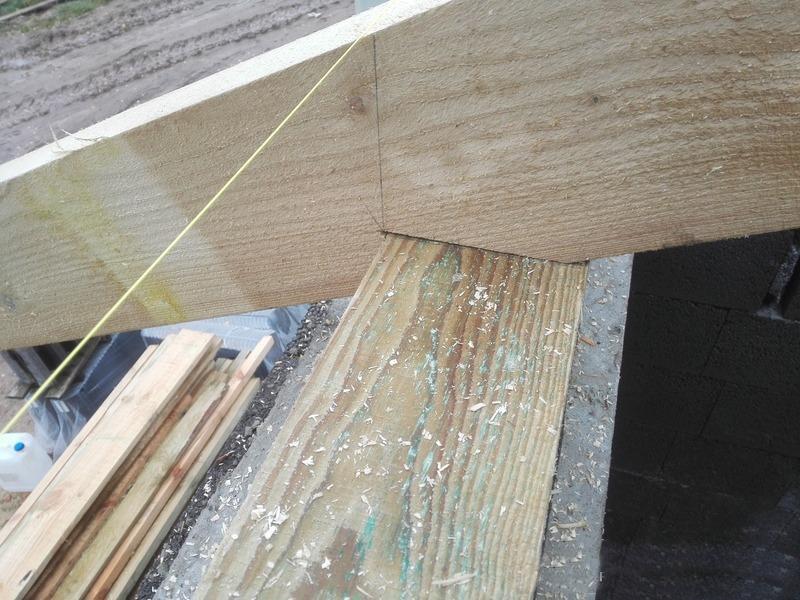
When building a rafter system, it is important to monitor every detail to ensure the reliability of the structure. Particular attention is paid to the attachment point of the rafters to the Mauerlat. It is in this place that the main part of the load is transferred to load-bearing walls. In this case, it is important not only how to fasten what to use, but also the accuracy of the cut. After all, if the board is not fully supported, then it can break and lead to the collapse of the roof. In this article we will look at how to cut rafters and what methods exist for this.
Depending on the constructive solution, availability interior walls and design load apply different kinds fastenings Each of them implies its own option for preparing rafters for joining with the Mauerlat. The three main mounting methods are listed below:
- hard;
- layered;
- sliding.
We will not consider the last option, since when using it there will be no need to make cuts. It is usually used when installing roofs on houses made of timber. It is most suitable, since wooden walls shrink over time. Because of this rafter system may change the geometry and leaks will appear.
In other options, you will have to make precise cuts. You will need accurate measuring instruments, construction pencil and electric or chainsaw.

The strength of the roof depends not only on how correctly the cuts were made. Consider the following tips:
- Select for rafters quality materials, because even if you make precise cuts, the block may not withstand the load. You can’t save money here, as this part takes all the load on itself.
- The mounting points with the Mauerlat must be free of wood defects, such as knots. Although they are stronger than wood, turbulences form around them, which break at the slightest load.
- When installing a roof, do not hesitate to ask for help, as this is a dangerous and responsible task.
Well-made connection unit rafter leg and the Mauerlat guarantees a long service life of the structure.
Cutting out a seat

It is important to understand that it is impossible to make a perfect cut on a construction site. The reasons may be different: lack of high-precision tools, uneven position of the Mauerlat, inconvenient position, and so on. Therefore, relative to the design value, the angle of inclination of the slope may change. The main thing here is to maintain a single line of rafter position.
The easiest way to make the same cut on the rafters is to use a template. True, this option is not suitable in all cases, as roofs are often uneven. Then you will have to calculate the angle and location of the cutting on each rafter individually.
For the base of the template, take a piece of board, a piece of fiberboard or plywood, even thick cardboard will do. On the workpiece, draw a line from the bottom edge at a distance of no more than a third of the width of the rafter. The same line must be drawn on all the beams that you plan to trim. The fact is that cutting deeper is not recommended due to loss of strength. Next, mark the points at which the rafters will be adjacent to the mauerlat, make a perpendicular line relative to the previous line.
Now let's move on to making the template, determining the angles of the vertical and horizontal parts of the notch. To do this, attach the workpiece to the end of the Mauerlat, maintaining the slope of the future roof. Opposite the corner there should be a point of intersection of the lines that were made before. Draw the lines of the triangle and cut out the resulting template.
Before transferring the markings to the rafters, check the accuracy finished product. Walk along the roof and check the degree of connection along the entire length of the Mauerlat. Make adjustments if necessary, but don't wait ideal option. Differences of 2-3 millimeters are acceptable.
Maximum concentration is important so as not to go beyond the outlined boundaries. If you are not sure about own strength, then use a hand tool. This way you will reduce the percentage of defects and the time for rework.
The second cut is made with an ax, since the power saw can be stuck. This also requires skill and strength. It is important to make sure that the ax is quite sharp, then the job will work better and you can avoid chipping.
Finally, check the resulting cut against the template and make adjustments if necessary. After which you can install the finished rafter leg or make seats on the remaining parts.
Trimming for direct joint with Mauerlat
A simpler option is to make a butt joint. To do this, you need to determine the location of the cut and its angle of inclination. For this purpose, two options can be used: theoretical and practical.
For theoretical method you need to have a good understanding of geometry and calculate the desired angle on paper. Divide the distance from the ridge to the eaves by the length of the rafter. So, you will get the cosine of the required angle. In order to transfer it to the workpiece, you can use either miter saw, or a special square.
If you don't have a special tool at hand, make a simple template. Take durable material, for example, chipboard. On the sheet, mark 500 mm along the bottom edge, then determine the tangent of the required angle and multiply by the measured length. This will give you the second side of a right triangle. By marking all the boundaries and cutting out the workpiece, get the desired angle. The sawed-off parts can be assembled immediately or you can wait until the entire set is completed.
In practice, you can easily mark a separate rafter by attaching it to the design position. To do this, position the beam so that its lower part is flush with the Mauerlat. Swipe horizontal line from the corner to the bottom of the rafter, it should be strictly parallel to the wall. Now you can safely saw off with any available tool and install the part. The remaining part will serve as a template for the remaining rafters only if the base is level.
Knowledge of geometry helps not only in determining the angle of the rafter leg, but also in determining the height of the roof, length individual elements and so on.
Recently, corner joints of slab materials with a miter bevel have become increasingly popular in the manufacture of furniture. In this article, our friend and colleague Sergei Novikov will share the secrets of making such a non-standard joint.
Unlike a joint with an acute angle, which, firstly, is quite traumatic, and secondly, is itself susceptible to chipping and deformation with minimal impact, this option is free from the above-mentioned disadvantages.
So, first, using a saw with a bar, we cut down the mating edges at an angle of 45 degrees. In principle, this can be done with sawing machine, But plunge saw with a tire (2 passes) against laminated chipboard gives better results.

So, we get two parts with sharp corners, let's move on directly to connecting them. 
To enhance the strength of the joint, we will need a lamellar router (I think we can get by with a regular one, but with special devices(so far there are only vague outlines in my head). 
These flat furniture dowels (slats) are inserted into the grooves selected by the slats. 
They prevent the parts from moving during displacement, and also add strength to the final connection, significantly increasing the gluing surface. 
We coat the mating surfaces with glue (any PVA-containing glue will do). 
We connect the parts and clamp them with clamps until the glue dries completely. 
After removing the clamps, glue streaks remain on the corner - they do not need to be removed, because... Later they will fall off on their own.

The next step is smoothing the corner. This is done either with an angular cutter (45 degrees) or with a cylindrical cutter, but for this the router must have an angular base. 
After cutting the corner, you get this trapezoidal profile. Now our task is to refine this corner. You can, of course, simply paint it or stick an edge, but the edge will not be important to hold, and when painting it will not be possible to obtain a neat, flat surface. 
The cut must be puttied. IN in this case Automotive putty with fiberglass is used (what was on hand), but it is better to use more homogeneous mixtures. 
Degrease the surface to be putty. The solution for this should not contain water. 
Apply the composition with a spatula, rubbing it into the pores and leveling. 
After final drying, we finally smooth the surface with a sanding block with fine sandpaper. 
Now let's paint it over. Cheap spray paint will work for this. 
We glue to protect the surface of the cut edge masking tape and cover with paint 2-3 times. 
For additional durability and shine, we open it with a layer of acrylic varnish.

We cut off any streaks of varnish that remain after it has completely dried with a utility knife. 
It seems nothing complicated, but the result is very interesting.
Half-tree cutting - simple and reliable way connect two identical parts at right angles. This method is useful when creating corner, cross and T-shaped joints. By marking and selecting half the thickness of the material in each part, you will get a neat and durable connection, which will become indispensable when assembling frames and timber structures.
Half-tree cutting is done different ways: using a router, circular or band saw. We'll show you how to create perfectly tight joints using a classic set of hand tools.
TOOLS
- carpenter's square;
- marking thicknesser;
- pencil or marking knife;
- axing saw;
- wide carpenter's chisel.
Do-it-yourself half-tree corner joints

Half-timber corner notch (overlapping) is the most common type of frame connection. Its logic is extremely simple: at the ends of both parts, recesses (folds) are cut out along the width of the counter part. The fold forms an edge and a shoulder - they must be perfectly smooth and strictly perpendicular to each other. In a high-quality connection, the surfaces of both parts fit tightly and form a joint without the slightest gap.
Connection marking
Create markings for the fold selection. To do this, use a carpenter's square, a surface planer and a marking knife.

Measure the length of the edge along the width of the mating part. Draw marking lines on the edges. Set the thicknesser to half the thickness of the part and make side markings.
Advice! When creating carpentry joints yourself, use a sharp marking knife instead of a pencil. It will ensure high marking accuracy and the absence of marks on finished part. In this case, the deepened line will become a convenient starting position for a chisel or auger saw.
Rebate cutting

Using a back saw, saw off the waste part on each part, carefully following the markings without strong pressure or jerking.

Using a wide chisel, clean the edge and shoulder, achieving the tightest possible fit of the parts.
T-shaped (T) connection

The lap joint is another variation of the half-timber joint, which is widely used in the creation of frame structures. In this case, the end of one part is adjacent to the middle of the second. On the first, a fold is cut out (according to a similar pattern as in corner connection), and to the second landing groove. Below is one of the schemes for creating such a groove manually.
Make markings on the front side, focusing on the width of the counter part.

Using a thicknesser and a square, mark the edges.

Make cuts in the waste part. They will facilitate subsequent sampling with a chisel.

Use a wide carpenter's chisel to remove the waste. Remove layers, moving from the center to the edges.

Clean the groove. The edge and shoulders must be perfectly smooth and meet strictly at right angles. This will ensure that the parts fit as tightly as possible.


On the issue of fixation
Half-timber joinery joints do not have a mechanical connection, so they are secured using gluing. We talked about this in detail in previous materials.
While drying, the structure must be secured with clamps. When placing the clamps, make sure that their pressure is distributed evenly. An incorrectly installed clamp can deform parts or disrupt the fit of the connection.
Unlike frame structures, logs or beams are strengthened using a different technology. In this case, screws, dowels or dowels are used to secure the connection.
There are a myriad of joints you can use to join wood pieces together. The names and classifications of joinery and carpentry joints, as a rule, vary significantly depending on the country, region and even school of woodworking. The skill lies in the precision of execution to ensure a properly functioning connection that can withstand the loads intended for it.
Initial information
Connection categories
All connections (in carpentry they are called ties) wooden parts according to their area of application can be divided into three categories (foreign version of the classification):
- box;
- frame (frame);
- for joining/merging.
Box connections are used, for example, in the manufacture drawers and arrangement of cabinets, frames are used in window frames and doors, and joining/merging is used to obtain parts of increased width/length.
Many compounds can be used in different categories, for example, butt joints are used in all three categories.
Preparation of material

Even planed lumber may need some preparation.
- Cut the material with a margin of width and thickness for further planing. Don't cut the length yet.
- Choose the best quality surface - the front side. Plane it along its entire length. Check with a straight edge.
After final leveling Make a mark on the front side with a pencil. - Plane the front - clean - edge. Check with a straight edge and a square against the front side. Use planing to smooth out any warping. Mark the clean edge.
- Using a thicknesser, mark the required thickness along all edges of the part contour. Plan to this risk. Check with a straight edge.
- Repeat for width.
- Now mark the length and the actual connections. Mark from the front side to the clean edge.
Marking lumber
Be careful when marking lumber. Make sufficient allowances for the width of cuts, planing thickness and connections.
Take all readings from the front side and the clean edge, on which place the appropriate marks. In frame and cabinet designs, these marks should face inward to improve manufacturing accuracy. To make sorting and assembling easier, number the parts on the front side as they are manufactured, to indicate, for example, that side 1 connects to end 1.

When marking identical parts, carefully align them and make markings on all workpieces at once. This will ensure the markup is identical. When marking profile elements, keep in mind that there may be “right” and “left” parts.
Butt joints
These are the simplest of carpentry joints. They can fall into all three categories of compounds.

Assembly

The butt joint can be strengthened with nails driven in at an angle. Drive the nails in randomly.
Trim the ends of the two pieces evenly and connect them. Secure with nails or screws. Before this, you can apply glue to the parts to strengthen the fixation. Butt joints in frame structures can be reinforced with a steel plate or a corrugated key with outside or with a wooden block secured from the inside.

Pin/dowel connections
Wooden dowels - today they are increasingly called dowels - can be used to strengthen the connection. These insertable round tenons increase shear (shear) strength and, due to the adhesive, secure the assembly more reliably. Dowel joints can be used as frame joints (furniture), box joints (cabinets) or for joining/splicing (panels).
Assembling the dowel connection
1. Carefully cut out all components to the exact dimensions. Mark the position of the crossbar on the face and clean edge of the post.
2. Mark center lines for the dowels on the end of the crossbar. The distance from each end should be at least half the thickness of the material. A wide crossbar may require more than two dowels.

Mark the center lines for the dowels at the end of the crossbar and use the square to transfer them to the rack.
3. Place the rack and bar front side up. Using the square, transfer the center lines to the stand. Number and label all connections if there is more than one pair of posts and crossbars.
4. Transfer these markings to the clean edge of the post and the ends of the crossbar.
5. From the front side, use a thicknesser to draw a line in the center of the material, crossing the marking lines. This will mark the centers of the holes for the dowels.

Use a thicknesser to draw a center line, crossing the marking lines, which will show the centers of the holes for the dowels.
6. Electric drill with twist drill or hand drill With a feather drill, drill holes in all parts. The drill must have a center point and scorers. The hole across the fibers should have a depth of approximately 2.5 times the diameter of the dowel, and the hole in the end should have a depth equal to approximately 3 times the diameter. For each hole, make an allowance of 2 mm; the dowel should not reach the bottom by this distance.
7. Use a countersink to remove excess fibers from the top of the holes. This will also make it easier to install the dowel and create space for the adhesive to secure the joint.
Nageli

The dowel should have longitudinal groove(now standard dowels are made with longitudinal ribs), along which excess glue will be removed when assembling the joint. If the dowel does not have a groove, then plan it flat on one side, which will give the same result. The ends should be chamfered to facilitate assembly and prevent damage to the hole by the dowel. And here, if the dowels do not have a chamfer, make it with a file or grind the edges of their ends.
Using centers to mark dowels
Mark and drill the crossbars. Insert special dowel centers into the holes for the dowels. Align the crossbar with the post markings and press the pieces together. The points of the centers will make marks on the stand. Drill holes through them. As an alternative, you can make a template from a wooden block, drill holes in it, fix the template on the part and drill holes for dowels through the holes in it.
Using a conductor for a dowel connection
A metal jig for dowel connections greatly facilitates marking and drilling holes for dowels. In box joints, the jig can be used at the ends, but it will not work on the faces of wide panels.

conductor for pin connections
1. Mark center lines on the front side of the material where the dowel holes should be. Select a suitable drill guide and insert it into the jig.
2. Align the alignment marks on the side of the jig and secure the movable support of the guide bushing.
3. Install the jig onto the part. Align the centering notch with the center line of the dowel hole. Tighten.
4. Install a drill depth stop on the drill in the required location.
Rally
To get a wider wooden part You can use dowels to connect two parts of the same thickness along the edge. Place two boards with their wide sides together, align their ends exactly, and clamp the pair in a vice. On the clean edge, draw perpendicular lines to indicate the center lines of each dowel. In the middle of the edge of each board, use a thicknesser to score marks across each previously marked center line. The intersection points will be the centers of the holes for the dowels.

The nail joint is neat and durable.
Notch / mortise connections
A notch, mortise or groove connection is called a corner or median connection, when the end of one part is attached to the layer and another part. It is based on a butt joint with an end cut made in the face. Used in frame (house frames) or box (cabinets) connections.
Types of jack/punch connections
The main types of notch joints are the t-notch in the dark/semi-dark (often this term is replaced by the term “flush/semi-dark”), which looks like a butt joint, but is stronger, the corner notch (corner connection) in the quarter and the corner notch in the dark/semi-dark. A corner notch into a rebate and a corner notch into a rebate with darkness/semi-darkness are made in the same way, but the rebate is made deeper - two-thirds of the material is selected.
Carrying out cutting
1. Mark a groove on the front side of the material. The distance between the two lines is equal to the thickness of the second part. Continue the lines to both edges.
2. Using a thickness gauge, mark the depth of the groove between the marking lines on the edges. The depth is usually made from one quarter to one third of the thickness of the part. Mark the waste portion of the material.
3. C-clamp securely fasten the part. Saw the shoulders on the outgoing side of the marking lines to the required depth. If the groove is wide, make additional cuts in the waste to make it easier to remove the material with a chisel.

Saw close to the marking line on the waste side, making intermediate cuts with a wide groove.
4. Using a chisel on both sides, remove excess material and check that the bottom is even. You can use a primer to level the bottom.

Use a chisel to remove waste, working from both sides, and level the bottom of the groove.
5. Check the fit; if the part fits too tightly, it may need to be trimmed. Check for squareness.
6. The notch connection can be strengthened in one of the following ways or a combination of them:
- gluing and clamping until the glue sets;
- screwing with screws through the face of the outer part;
- nailing at an angle through the face of the outer part;
- Nailing obliquely across a corner.

The notch connection is quite strong
Groove and side tongue joints
This is a combination of a quarter cut and a rebate cut. It is used in the manufacture of furniture and the installation of slopes for window openings.
Making a connection

1. Make the ends perpendicular to the longitudinal axes of both parts. Mark the shoulder on one part, measuring the thickness of the material from the end. Continue marking on both edges and the front side.
2. Mark the second shoulder from the end side; it should be at a distance of one third of the thickness of the material. Continue on both edges.
3. Using a thickness gauge, mark the depth of the groove (one-third of the thickness of the material) on the edges between the shoulder lines.
4. Using a hacksaw, saw through the shoulders to the thickness line. Remove waste with a chisel and check the alignment.
5. Using a thicknesser with the same setting, mark a line on the back side and on the edges of the second part.
Adviсe:
- Mortise and tongue-and-groove joints can be easily made using a router and a suitable guide - either for the groove only, or for both the groove and the tongue. Recommendations for proper operation with a router, see p. 35.
- If the comb fits into the groove too tightly, trim the face (smooth) side of the comb or sand it with sandpaper.
6. From the front side, use a thicknesser to mark the edges towards the end and at the end itself. Saw along the lines of the planer with a hacksaw. Don't cut too deep as this will weaken the joint.
7. Using a chisel from the end, remove the waste. Check fit and adjust if necessary.
Half-tree connections
Half-timber joints are frame joints that are used to join parts together face to face or along an edge. The joint is made by removing the same amount of material from each piece so that they fit flush with each other.
Types of half-tree connections
There are six main types of half-tree joints: transverse, angular, dark, miter angled, dovetail and splicing.

Making a half-tree corner connection
1. Align the ends of both parts. On the top side of one of the parts, draw a line perpendicular to the edges, stepping back from the end to the width of the second part. Repeat on bottom side second detail.
2. Set the thicknesser to half the thickness of the parts and draw a line on the ends and edges of both parts. Mark the waste on the top side of one piece and the bottom side of the other piece.
3. Clamp the part in a vice at an angle of 45° (faces vertical). Saw carefully along the grain, close to the thickness line on the waste side, until the saw is diagonal. Turn the piece over and continue cutting carefully, gradually lifting the saw handle until the saw is aligned with the shoulder line on both edges.
4. Remove the part from the vice and place it on the surface. Press it tightly to the tsulaga and clamp it with a clamp.
5. Saw the shoulder to the previously made cut and remove the waste. Use a chisel to smooth out any unevenness in the sample. Check that the cut is neat.
6. Repeat the process on the second piece.
7. Check the fit of the parts and, if necessary, level them with a chisel. The connection must be rectangular, flush, without gaps or backlash.
8. The connection can be strengthened with nails, screws, and glue.
Miter corner connections

Miter corner joints are made by bevelling the ends and hide the end grain and are aesthetically more consistent with the angular rotation of the decorative trim.
Types of miter corner joints
To bevel the ends in a miter joint, the angle at which the parts meet is divided in half. In a traditional connection, this angle is 90°, so each end is cut at 45°, but the angle can be either obtuse or acute. In uneven miter corner joints, parts with different widths are connected.
Performing miter joints
1. Mark the length of the pieces, keeping in mind that it should be measured along the long side, since the bevel will reduce the length inside the corner.
2. Having decided on the length, mark a line at 45° - on the edge or on the face, depending on where the bevel will be cut.
3. Using a combination square, transfer the markings to all sides of the part.
4. When cutting by hand, use a miter box and a hacksaw or hand miter saw. Press the piece firmly against the back of the miter box - if it moves, the bevel will be uneven and the joint will not fit well. If you are simply sawing by hand, watch the process so as not to deviate from the marking lines on all sides of the part. A power miter saw, if you have one, will make a very neat bevel.
5. Place the two pieces together and check the fit. You can correct it by trimming the bevel surface with a plane. Firmly fix the part and work with a sharp plane, setting the knife overhang to a small extent.
6. The connection should be nailed through both parts. To do this, first place the parts on the surface and drive nails into the outer side of the bevel so that their tips slightly appear from the bevels.

Place nails in both parts so that the tips protrude slightly from the surface of the bevel.
7. Apply glue and press the joint tightly so that one part protrudes slightly and overlaps the other. First, drive nails into the protruding part. Under the blows of the hammer when hammering nails, the part will move slightly. The surfaces must be level. Nail the other side of the joint and countersink the nail heads. Check for squareness.

Drive the nails into the protruding part first and the hammer will move the joint into position.
8. If due to unevenness of the workmanship there is a small gap, smooth the connection on both sides with the round blade of a screwdriver. This will move the fibers, which will close the gap. If the gap is too large, you will either have to redo the connection or seal the gap with putty.
9. To strengthen the corner joint, you can glue a wooden block inside the corner if it is not visible. If important appearance, then the connection can be made on a tenon or secured with veneer dowels. Dowels or lamellas (standard flat plug-in tenons) can be used inside flat joints.

Miter splicing and cutting connection
A miter splice connects the ends of parts located on the same straight line, and a rip splice is used when it is necessary to connect two profile parts at an angle to each other.
Miter splicing

When miter splicing, the parts are connected with identical bevels at the ends in such a way that the same thickness of the parts remains unchanged.
Connection with cutter
A connection with a cut (with a cut, with a fit) is used when it is necessary to connect two parts with a profile in a corner, for example, two plinths or cornices. If the part moves during the process of fastening it, the gap will be less noticeable than with a miter joint.
1. Secure the first baseboard in place. Move the second plinth located along the wall close to it.

Clamp the first baseboard in place and press the second baseboard against it, lining it up with the wall.
2. Run a small wooden block with a pencil pressed to it along the profile surface of the fixed baseboard. The pencil will leave a marking line on the plinth being marked.

Using a block with a pencil pressed to it, with the tip pointed at the second plinth, draw along the relief of the first plinth, and the pencil will mark the cut line.
3. Cut along the marking line. Check the fit and adjust if necessary.
Complex profiles
Place the first plinth in place and, placing the second plinth in the miter box, make a bevel on it. The line formed by the profile side and the bevel will show the required shape. Cut along this line with a jigsaw.
Lug connections

Lug joints are used when there is a need to connect intersecting parts located “On Edge”, either at the corner or in the middle (for example, the corner of a window sash or where a table leg meets a crossbar).
Types of lug connections
The most common types of eyelet connections are corner and T-shaped (T-shaped). For strength, the connection must be glued, but it can be strengthened with a dowel.
Making an eyelet connection
1. Mark the same as for, but divide the thickness of the material by three to determine one third. Mark the waste on both parts. On one part you will need to select the middle. This groove is called an eye. On the second part, both side parts of the material are removed, and the remaining middle part is called a tenon.
2. Saw along the grain to the shoulder line along the marking lines on the waste side. Use a hacksaw to cut out the shoulders, and you will get a tenon.
3. Working from both sides, remove material from the eye with a chisel/mortise chisel or jigsaw.
4. Check the fit and adjust with a chisel if necessary. Apply glue to the joint surfaces. Check for squareness. Using a C-clamp, clamp the joint while the glue hardens.

Tenon to socket connection
Tenon to socket connections, or simply tenon joints, are used when two parts are connected at an angle or intersection. It is probably the strongest of all frame joints in joinery and is used in the making of doors, window frames and furniture.
Types of tenon-to-socket connections
The two main types of tenon joints are the usual tenon-to-socket joint and the stepped tenon-to-socket joint (semi-dark). The tenon and socket make up approximately two-thirds of the width of the material. The socket is widened on one side of the groove (semi-dark), and a tenon step is inserted into it from its corresponding side. Semi-darkness helps prevent the thorn from being turned out of the socket.
Conventional tenon-to-socket connection

1. Determine the joint position on both pieces and mark all sides of the material. The marking shows the width of the intersecting part. The tenon will be at the end of the crossbar, and the socket will go through the post. The tenon should have a small allowance in length for further stripping of the joint.
2. Select a chisel that is as close in size as possible to a third of the thickness of the material. Set the thicknesser to the size of the chisel and mark the socket in the middle of the post between the previously marked marking lines. Work from the front side. If desired, you can set the thicknesser solution to a third of the thickness of the material and work with it on both sides.
H. In the same way, mark the tenon on the end and both sides until you mark the shoulders on the crossbar.
4. In a vice, clamp an auxiliary support in the form of a piece of wood high enough so that you can attach the stand to it, turned “on edge.” Secure the stand to the support, placing the clamp next to the marking of the socket.
5. Cut out a nest with a chisel, making an allowance inwards of about 3 mm from each end so as not to damage the edges when removing waste. Hold the chisel straight, maintaining parallelism
its edges are the plane of the rack. Make the first cut strictly vertically, placing the sharpening bevel towards the middle of the socket. Repeat from the other end.
6. Make several intermediate cuts, holding the chisel at a slight angle and with the sharpening bevel down. Select a retreat, using the chisel as a lever. Having gone deeper by 5 mm, make more cuts and select a waste. Continue until about halfway thick. Turn the piece over and work the same way on the other side.
7. After removing the main part of the waste, clean out the nest and cut off the previously left allowance to the marking lines on each side.
8. Cut a tenon along the fibers, running a hacksaw along the marking line on the waste side, and cut out the shoulders.
9. Check fit and adjust if necessary. The shoulders of the tenon should fit neatly into the post, the connection should be perpendicular and have no play.
10. To secure, you can insert wedges on both sides of the tenon. The gap for this is made in the socket. Working with a chisel from the outside of the socket, widen it to about two-thirds of the depth with a 1:8 slope. The wedges are made with the same bias.
11. Apply glue and squeeze tightly. Check for squareness. Apply glue to the wedges and drive them into place. Saw off the tenon allowance and remove excess glue.

Other tenon joints
Tenon joints for window frames and doors are somewhat different from tenon joints in semi-darkness, although the technique is the same. Inside there is a fold and/or lining for glass or panel (panel). When making a tenon-to-socket connection on a part with a rebate, make the plane of the tenon in line with the edge of the rebate. One of the shoulders of the crossbar is made longer (to the depth of the fold), and the second is made shorter so as not to block the fold.
Tenon joints for parts with overlays have a shoulder that is cut to match the profile of the overlay. An alternative is to remove the trim from the edge of the socket and make a bevel or cut to match the mating piece.
Other types of tenon-to-socket connections:
- Side tenon - in the manufacture of doors.
- A hidden beveled tenon in semi-darkness (with a beveled step) - to hide the tenon.
- Tenon in the dark (tenon steps on both sides) - for relatively wide parts, such as bottom harness(bar) door.
All these connections can be through, or they can be blind, when the end of the tenon is not visible from reverse side racks. They can be strengthened with wedges or dowels.
Rally

Wide, high quality timber is becoming increasingly difficult to find and very expensive. Moreover, such wide boards are subject to very large shrinkage deformations, which makes working with them difficult. To join narrow boards along the edges into wide panels for tabletops or workbench covers, they use bonding.
Preparation
Before starting the bonding itself, you must do the following:
- Select boards if possible radial sawing. They are less susceptible to shrinkage deformations than tangential sawn timber. If tangentially sawn boards are used, then place their core side alternately in one direction and the other.
- Try not to combine materials with different sawing methods into one panel.
- Never join boards of different types of wood unless they have been properly dried. They will shrink and crack differently.
- If possible, place the boards with the grain in the same direction.
- Be sure to cut the material to size before joining.
- Use only good quality glue.
- If the wood will be polished, select the texture or color.
Rallying on a smooth fugue
1. Lay out all the boards face up. To facilitate subsequent assembly, mark the edges with a continuous pencil line drawn along the joints at an angle.
2. Plane straight edges and check fit to appropriate adjacent boards. Align the ends or pencil lines each time.
3. Make sure there are no gaps and that the entire surface is flat. If you squeeze the gap with a clamp or fill it with putty, the connection will subsequently crack.
4. When planing short pieces, clamp two in a vise, right sides together, and plane both edges at the same time. There is no need to maintain the squareness of the edges, since when joining they will mutually compensate for their possible tilt.
5. Prepare as for a butt joint and apply glue. Using squeezing and rubbing, connect the two surfaces, squeezing out excess glue and helping the surfaces “suck” to each other.

Other ways to rally
Other bonding connections with different strengths are prepared in the same way. These include:
- with dowels (dowels);
- in tongue and groove;
- at a quarter.
Gluing and fixing with clamps

Gluing and fixing glued parts is an important part of woodworking, without which many products will lose strength.
Adhesives
The glue strengthens the connection, holding the parts together so that they cannot be easily pulled apart. When working with adhesives, be sure to wear protective gloves and follow the safety instructions on the packaging. Clean the product from excess glue before it sets, as it can dull the plane knife and clog the abrasive sandpaper.
PVA (polyvinyl acetate)
PVA glue is a universal wood glue. While still wet, it can be wiped off with a cloth dampened with water. It perfectly glues loose surfaces, does not require long-term fixation for setting and sets in about an hour. PVA gives a fairly strong connection and sticks to almost any porous surface. Provides a permanent connection but is not heat or moisture resistant. Apply with a brush, or for large surfaces, dilute with water and apply with a paint roller. Since PVA glue has water base, then shrinks when setting.
Contact glue
Contact adhesive bonds immediately after application and joining of parts. Apply it to both surfaces and when the glue is dry to the touch, press them together. It is used for laminate or veneer to chipboard. No fixation required. Can be cleaned with solvent. Contact adhesive is flammable. Handle it in a well-ventilated area to reduce fumes. Not recommended for outdoor use as it is not moisture or heat resistant.
Epoxy adhesive

Epoxy glue is the strongest of the adhesives used in woodworking, and the most expensive. This is a two-component resin-based adhesive that does not shrink when set and softens when heated and does not creep under load. Waterproof and bonds to almost all materials, both porous and smooth, with the exception of thermoplastics such as polyvinyl chloride (PVC) or plexiglass ( organic glass). Suitable for outdoor use. In an uncured form, it can be removed with a solvent.
Hot melt adhesive
Hot melt, solventless adhesive will stick to almost anything, including many plastics. Typically sold in the form of glue sticks that are inserted into a special electric glue gun. Apply glue, connect the surfaces and compress for 30 seconds. No fixation required. Can be cleaned with solvents.
Fixation clips
There are clamps various designs and sizes, most of which are called clamps, but usually only a couple of varieties are needed. Be sure to place a spacer between the clamp and the workpiece. wood waste to avoid indentations from the applied pressure.
Gluing and fixation technique
Before gluing, be sure to assemble the product “dry” - without glue. Lock as necessary to check connections and dimensions. If everything is fine, disassemble the product, arranging the parts in a convenient order. Mark the areas to be glued and prepare clamps with jaws/stops set at the required distance.
Frame assembly
Using a brush, spread the glue evenly onto all surfaces to be glued and quickly assemble the product. Remove excess glue and secure the assembly with clamps. Apply even pressure to compress the joints. The clamps must be perpendicular and parallel to the surfaces of the product.
Place the clamps as close to the connection as possible. Check the parallelism of the crossbars and align if necessary. Measure the diagonals - if they are the same, then the rectangularity of the product is maintained. If not, then a light but sharp blow to one end of the post can straighten the shape. Adjust the clamps if necessary.
If the frame does not lie flat on a flat surface, tap the protruding areas with a mallet through a block of wood as a spacer. If this does not help, you may need to loosen the clamps or use clamps to secure a block of wood across the frame.
GLUING OF CONNECTIONS ON THE MC
Get good connection it's quite difficult to do it well on the framework. When you glue and clamp corners, the pieces always move.
I found a simple solution. Before gluing on the back side of the frame, I fix the corners with one or two brackets (Fig. 1).
Staples allow you to open the front side of the joint and introduce glue into it (Fig. 2). In addition, when tightening the clamps, they keep the corners aligned (Fig. 3). Once the glue has hardened, the staples can be easily removed.
HOW TO GET RID OF Pruning
No matter how adjusted thickness planer, the ends of the boards always end up being cut deeper than necessary.
To reduce waste, I add slats to the work piece that can be sacrificed. They are approximately 150 mm longer than the workpiece, so they get all the trimming. These slats on the sides of the workpiece are secured with small drops of hot melt adhesive, and then the “sandwich” is run through the machine. Once the work piece is planed to size, the auxiliary slats are easy to remove.

SHELF HOLDERS CONDUCT
When installing shelves, a lot of time is spent marking and drilling holes for their supports. This must be done very accurately. Therefore, in order to do without measurements at all, I use a simple device. It is a wooden jig with four holes. Two of them have dowels inserted into them as guides.
First, drill two holes in the wall. Then insert the dowels into them and use the jig to drill the next two holes. Then move the jig into the holes you just drilled, prepare the next pair of holes, and so on. As a result, all holes will be drilled at the same distance from each other.
FLAP FOR DUST COLLECTOR
I recently purchased a dust collector for my workshop. It is convenient to work with it if you add a damper, which I decided to make from plywood (see photo). The manufacture of the damper began by cutting out two pieces of 20 mm thick plywood with holes with a diameter equal to the outer diameter of the pipes.
Between the plywood plates I inserted 3 mm thick spacers, which created a gap for the damper. Then I assembled the entire structure using glue and screws. I made the sliding flap 3 mm thick. I glued a wooden handle to its upper end, and screwed a screw into the lower end, preventing the damper from falling out in the open position.

Then I cut and installed two scraps from the dust collector pipe in the plywood so that they were flush with the internal ribs of the holes in the plywood.
Protractor
I work a lot with a jigsaw, and often have to change the inclination of its table. But the simplest scale underneath is not very accurate and difficult to read. So I made a protractor from a cheap plastic protractor. This wood block with a protractor attached to the side (Fig. 1). A piece of wire hung in the center shows the angle of inclination (Fig. 2). When working with a protractor, first adjust the protractor so that the wire arrow shows 90°, and then measure the inclination of the table.

SHARPENING V-CHISEL
Compared to a regular chisel, sharpening a wood carving tool is a little more difficult.
Sharpening the front sides. Sharpening V-shaped tool It starts with a bevel on the face and is similar to sharpening a regular chisel. Since the V-shaped tool has two angled sides, both need to be sharpened.
Use a medium grit stone with water or oil. When sharpening, hold the chisel at an angle of approximately 20°-25° and move it in short strokes back and forth along the block (Fig. 1). It is necessary to achieve equal sharpening on both sides. To do this, make several passes on one side, then the same number of passes on the other. Once sharpened, you will see a small burr running across each inside edge. Remove it by polishing the inside of the cutter on the leather belt.
Removing the hook.
When the burr is removed, outer corner a small hook remains (Fig. 2a). If you do not remove it, the tool will be difficult to operate. Remove the hook by successively rotating the tip of the chisel back and forth across a medium-grit block (Fig. 2).
Polishing. Polishing removes tiny nicks on cutting edge, where the outer and inner sides meet. By removing the nicks, you will make the tool much sharper. To polish an edge, leather belt Apply a little GOI paste and repeat the sharpening steps (Fig. 3).

INSTALLING THE DRAWER PULLER
Wooden slides are traditional, but they can sag under heavy load if, for example, a drawer in a buffet is filled with cutlery. Fully retractable ball and roller mechanisms do not jam and make it easy to reach items lying against the back wall. The full extension mechanism must be mounted with the guide rails installed at the same height. This is difficult to do in a buffet, since the edges of the guide rails are usually rounded, and therefore there is no “reference point”.
In a buffet, drawer mounting jumpers can be attached to the lid rather than to the sides. Therefore, the bar must be pressed to the bottom edge of the jumper so that a protrusion is formed. After installing the guides in place, they are exactly flush with the bottom edge of the jumpers and at the same level.

HOW TO MAKE RIGHT ANGLES
Usually the edging strips are attached to an already made body - you just need to glue them and press them into place with clamps.
On the sideboard, I added vertical edging to the sides before I assembled the cabinet. And instead of butt joints, I cut out the mortise/tenon joints to increase strength and keep the parts aligned when clamped with clamps.
Keeping parts aligned is not the same as keeping them at right angles. The problem is not in the connection, but in the clamps. If the clamps are not accurately centered on the joint, they tend to deflect the edge away from right angle(Fig. 1).
One solution to the problem is to make sure the clamps are perfectly centered. But The best way- insert pressing blocks into the corner of the assemblies (Fig. 2). Then the assembly will automatically be at right angles to the side walls.

CUTTING VOLUME PANELS
Cutting out the long sides of the panels is not a problem. But cutting short ends less than 150mm wide is difficult.
When feeding short ends, the panel is unstable, especially when there is only 5 mm of supporting surface between the ruler and the disk. To press the part tightly against the longitudinal ruler, your hands must pass very close to the disk.
Attach a tall auxiliary ruler to the longitudinal ruler. Then place the panel on the saw and press it firmly.
Then, holding the slab in place, hand vice press a couple wooden planks to the panel so that they lie flat on the top edge of the auxiliary ruler. This will provide you with additional support.
CHAMMER CLEANING
When cutting volumetric panels on a circular saw, marks from the disc often remain on the bevels. Most quick way To remove them, use a stripping block with an edge that matches the shoulder of the panel field.
GENTLE PINE
Pine is a soft wood that requires a special approach. Many difficulties arise when sanding and finishing pine. It slips easily. To move large items, use a sheet of plywood - place the item on the plywood, not on the concrete floor. This will protect the ends of the boards from chipping.
Most scratches can be cleaned up quickly. And dents can be removed using a hot iron and a damp cloth, since the wood absorbs moisture from the steam and the dents disappear.
Before processing pine, make sure that the circular saw blade is sharp: a dull disk tears the soft fibers and does not cut them. Pay attention to the tariness of the disc. During cutting, the resin creates a lot of resistance. You can remove layered resin by washing the disc with a household cleaner.
When drilling pine, the first pass should be made with a hand drill switched to reverse. In this case, the teeth on the drill scrape the outside diameter of the hole, thinly cutting away the wood fibers.
Pine wood fibers can be torn not only by sawing and drilling, but also by removing dried glue, especially if it is scraped. Do not apply too much glue to the joint and clean off any excess glue immediately before it completely hardens.
Stripping pine has its own specific features. Usually a grinder is used for this. But it leaves almost invisible spiral marks on the pine. Therefore, finish sanding your items by hand.
Use a stripping block. If you strip without a block, you will remove more young wood as it is softer, resulting in a wavy rather than smooth surface.
There are two things to consider when finishing pine. Firstly, pine absorbs stain unevenly, which is why dark spots appear on the wood. Try deresining the wood first, which will even out the stain's absorption. Secondly, if possible, choose light stains. They don't highlight dents, broken grain or spiral marks as much as dark ones.

LONGITUDINAL SAWING OF CROSS-WARVED BOARDS
Such boards can be sawn lengthwise in two ways, and both have their advantages and disadvantages.
The board lies with the concave side down. When cutting a board longitudinally in this position, it rests on two edges. Therefore, when making most cuts, the board lies stable. But problems can arise in the last centimeters of the cut. When you finish cutting, the cuttings between the ruler and the disc may fall down and get stuck against the disc. To reduce the risk, quickly move the workpiece forward in the last centimeters.
The board lies with the concave side up. In this option, there will be no danger of jamming at the end of the cut. But the board itself will turn out to be less stable during the entire process.
Perhaps the best (and safest) way to cut a warped board lengthwise and avoid kickback is to use a bandsaw rather than a circular saw.
Let's do without a drill
To assemble furniture, you need to drill many holes to install fittings, or additives, as the professionals say. Moreover, this work requires high precision. Otherwise, what kind of assembly will it be? One frustration! If it happens at all.
Just pick up a drill and start drilling parts - this option disappears immediately. The axis of the hole must be strictly in the specified planes. This condition is especially difficult to fulfill when drilling the end of a part - for example, a shelf.
1. Alternatively, you can use a conductor. I work with a conductor from the KWB company, it is sold in construction supermarkets. The device allows you to drill holes of different diameters at a given distance from the edge of the edge. For a novice furniture maker or an experienced one, but working at a distance from the workshop, such a device is quite suitable. But you can’t work like this all the time. It’s not a good idea to carry a tool in your hand all day, and even try to hold a part standing straight on an edge! All this is tedious and leads to a decrease in the quality of work. There is only one way out - to organize your work so that the part is on the work table. And the tool performing the drilling stood on it. The operator will only have to place the parts on the table in a given position and move the tool back and forth.
Based on these introductory notes, I made a simple device (machine), which, it seems to me, will be useful not only for professionals, but also for home craftsmen who have limited time to do what they love. Industry, as far as I know, has not yet come up with such a necessary device.
2. For the machine I adapted an engine from a sharpener. True, the thread pitch of the motor shaft and the drill chuck turned out to be different. I had to use the services of a turner. The sharpener motor is asynchronous. Compared to a drill, it works almost silently. And due to the absence of elements that work with friction - a commutator and brushes - its service life is significantly increased.
3. The basis of the machine is a structure made of laminated chipboard from an old cabinet. The engine is mounted on a plywood base, with two aluminum channels attached to the bottom. Thanks to these slides and the grooves under them, formed on the table with laminated chipboard blocks, the engine can only move back and forth relative to the work table on which the part is installed.
4. Aluminum stop square pipe Additionally, it also functions as a channel for removing chips and dust. A vacuum cleaner is connected to it. The distance from the drill axis to the work table surface is 8 mm. This is enough to add all the fittings. If you need a larger value, you just need to place a couple of strips of a given thickness under the engine sole.
5. Drilling precise holes under the dowels in the edge of the part.