Thermostats are widely used in modern household appliances, automobiles, heating and air conditioning systems, manufacturing, refrigeration and furnace applications. The operating principle of any thermostat is based on turning on or off various devices after reaching certain temperature values.
Modern digital thermostats are controlled using buttons: touch or regular. Many models also come with a digital panel that displays the set temperature. The group of programmable thermostats is the most expensive. Using the device, you can provide for temperature changes hourly or set the required mode for a week in advance. The device can be controlled remotely: via a smartphone or computer.
For complex technological process, for example, a steel-smelting furnace, making a thermostat with your own hands is a rather difficult task that requires serious knowledge. But any home craftsman can assemble a small device for a cooler or incubator.
In order to understand how a temperature controller works, consider a simple device that is used to open and close the damper of a mine boiler and is activated when the air is heated.
To operate the device, 2 aluminum pipes, 2 levers, a return spring, a chain that goes to the boiler, and an adjustment unit in the form of a faucet axle box were used. All components were installed on the boiler.
As is known, the coefficient of linear thermal expansion aluminum is 22x10-6 0C. When heated aluminum pipe one and a half meters long, 0.02 m wide and 0.01 m thick up to 130 degrees Celsius, an elongation of 4.29 mm occurs. When heated, the pipes expand, causing the levers to shift and the damper to close. When cooling, the pipes decrease in length, and the levers open the damper. The main problem when using this scheme is that it is very difficult to accurately determine the response threshold of the thermostat. Today, preference is given to devices based on electronic elements.

Scheme of operation of a simple thermostat
Typically, relay-based circuits are used to maintain a set temperature. The main elements included in this equipment are:
- temperature sensor;
- threshold circuit;
- actuator or indicator device.
Semiconductor elements, thermistors, resistance thermometers, thermocouples and bimetallic thermal relays can be used as sensors.
The thermostat circuit reacts when the parameter exceeds a given level and turns on the actuator. The most simple option such a device is an element on bipolar transistors. The thermal relay is based on a Schmidt trigger. A thermistor acts as a temperature sensor - an element whose resistance changes depending on the increase or decrease in degrees.
R1 is a potentiometer that sets the initial offset on thermistor R2 and potentiometer R3. Due to the adjustment, the actuator is activated and relay K1 is switched when the resistance of the thermistor changes. In this case, the operating voltage of the relay must correspond to the operating power supply of the equipment. To protect the output transistor from voltage surges, a semiconductor diode is connected in parallel. The load value of the connected element depends on the maximum current of the electromagnetic relay.

Attention! On the Internet you can see pictures with thermostat drawings for various equipment. But quite often the image and description do not correspond to each other. Sometimes the pictures may simply show other devices. Therefore, production can begin only after carefully studying all the information.
Before starting work, you should decide on the power of the future thermostat and the temperature range in which it will operate. The refrigerator will require some elements, and the heating will require others.
Three element thermostat
One of the elementary devices, using an example of which you can assemble and understand the principle of operation, is a simple do-it-yourself thermostat designed for a fan in a PC. All work is done on a breadboard. If there are problems with the pin, then you can use a solderless board.
The thermostat circuit in this case consists of only three elements:
- power MOSFET transistor (N channel), you can use IRFZ24N MOSFET 12 V and 10 A or IFR510 Power MOSFET;
- potentiometer 10 kOhm;
- NTC thermistor 10 kOhm, which will act as a temperature sensor.
The temperature sensor reacts to an increase in degrees, due to which the entire circuit is activated and the fan turns on.
Now let's move on to the setup. To do this, turn on the computer and adjust the potentiometer, setting the value for the fan turned off. At the moment when the temperature approaches critical, we reduce the resistance as much as possible before the blades rotate very slowly. It is better to do the setup several times to make sure the equipment is working effectively.

The modern electronics industry offers elements and microcircuits that differ significantly in appearance and technical specifications. Each resistance or relay has several analogues. It is not necessary to use only those elements that are indicated in the diagram; you can take others that match the parameters of the samples.
Thermostats for heating boilers
When adjusting heating systems It is important to accurately calibrate the device. To do this you will need a voltage and current meter. To create a working system, you can use the following diagram.

Using this scheme, you can create outdoor equipment to control solid fuel boiler. The role of the zener diode here is performed by the K561LA7 microcircuit. The operation of the device is based on the ability of a thermistor to reduce resistance when heated. The resistor is connected to the electricity voltage divider network. The required temperature can be set using variable resistor R2. The voltage is supplied to the 2I-NOT inverter. The resulting current is supplied to capacitor C1. A capacitor is connected to 2I-NOT, which controls the operation of one trigger. The latter is connected to the second trigger.
Control temperature goes according to the following scheme:
- as the degrees drop, the voltage in the relay increases;
- upon reaching certain value the fan connected to the relay turns off.
It is better to solder on a mole rat. As a battery, you can take any device operating within 3-15 V.
Carefully! Installation homemade devices any purpose on heating systems can lead to equipment failure. Moreover, the use similar devices may be prohibited at the level of services providing communications in your home.
Digital thermostat
In order to create a fully functioning thermostat with accurate calibration, you cannot do without digital elements. Consider a device for monitoring temperatures in a small storage area for vegetables.
The main element here is the PIC16F628A microcontroller. This chip provides control of various electronic devices. The PIC16F628A microcontroller contains 2 analog comparators, an internal oscillator, 3 timers, CCP comparison modules and USART data transfer exchange modules.
When the thermostat is operating, the value of the existing and set temperature is supplied to MT30361 - a three-digit indicator with a common cathode. In order to set the required temperature, use the following buttons: SB1 – to decrease and SB2 – to increase. If you carry out the adjustment while simultaneously pressing the SB3 button, you can set the hysteresis values. The minimum hysteresis value for this circuit is 1 degree. Detailed drawing can be seen on the plan.

When creating any of the devices, it is important not only to correctly solder the circuit itself, but also to think about how best to place the equipment. It is necessary that the board itself is protected from moisture and dust, otherwise it cannot be avoided short circuit and failure individual elements. You should also take care to insulate all contacts.
Video
In rainy, snowy or slushy weather, you always need to dry your shoes after going outside. In order not to carry wet shoes to the radiator every time, it was decided to make a low-power heated floor for drying shoes in the hallway, near front door. As you know, to control the temperature of heated floors, you need a thermostat; you can buy one, but it is much more pleasant to assemble the device yourself.
Specifications:
- Maximum switching current: depending on the triac used and its cooling.
- Operating voltage: ~230V
- Temperature range at specified ratings: +35…+55°C
- Temperature sensor: remote, NTC (negative temperature coefficient) type
Thermostat operation
When the device is turned on, the network AC voltage, through a transformerless power supply (R1,R2,C1,C3,C5,VD1,VD2) is rectified and stabilized to 15V, the green LED indicates the presence of voltage. A divider consisting of R4, R5 and R9 sets the threshold for turning on/off the thermostat, and since the floor is cold, R9 (thermistor) has a maximum resistance of about 10 kOhm, while a voltage above 2.5 V is supplied to the regulating input of the zener diode TL431 through R4, R5, The zener diode is open. The current passes through the chain VD3, R6, HL2, U1, the optosimistor is open, the red diode indicates this. The open optosimistor U1 forms a divider R7, R8, C2, the triac VS1 turns on, the floor heats up. At the moment when the floor temperature increases, the resistance of the R9 sensor (thermistor) decreases and, as a result, a moment comes when the voltage at the zener diode’s regulatory input becomes lower than the reference 2.5V, TL431 is closed, followed by the optosimistor and triac, the red LED goes out, heating section is disabled. As the floor cools by a few degrees, the process is repeated, and the device maintains the set temperature.
Setup and installation
R4 sets the maximum temperature, the lower the resistance R4, the higher the maximum heating temperature of the heating section. R5 sets minimum temperature The higher the resistance rating R5, the wider the temperature control range. R9 (thermistor) is a temperature sensor, it reduces its resistance as the temperature rises, thus it controls the on/off of the thermostat depending on the floor temperature. Using R7 you can adjust the power at the output of the thermostat.
The threshold for turning on/off the thermostat should be adjusted after installing the R9 sensor. The sensor terminals must be insulated, for example heat shrink tube.


The sensor should be installed near the heating section, for example between the turns of the heating cable.

All cables and the sensor must be puttied, and the ends must be brought into the distribution box. In the future, tiles will be laid on this floor.

In my case, the thermostat housing is made from an unnecessary RJ-45 socket

The board is routed and adjusted for a specific case. And yes, I advise you to use angular screw terminal blocks with straight terminal blocks - it will be very inconvenient.


The power of the heating section is 300 W, the triac must be installed through a mica gasket on a radiator of suitable dimensions, with an area of 50 cm2. If the power of the heating section does not exceed 150W, then you can do without a radiator.


Good luck to all! Take care of your health!
Attention! The thermostat circuit does not have protection against overheating of the heating section!
ZY: See comments to the article.
List of radioelements
| Designation | Type | Denomination | Quantity | Note | Shop | My notepad | |
|---|---|---|---|---|---|---|---|
| Semiconductor elements | |||||||
| VS1 | Triac | BT136-600E | 1 | BT139-600 | To notepad | ||
| U1 | Optocoupler | MOC3061M | 1 | MOC3041 | To notepad | ||
| VD1 | Diode bridge | DB104 | 1 | To notepad | |||
| VD2 | Zener diode | 1N4744A | 1 | To notepad | |||
| VD3 | Voltage reference IC | TL431 | 1 | To notepad | |||
| HL1 | Light-emitting diode | L-132XGD | 1 | green | To notepad | ||
| HL2 | Light-emitting diode | L-132XID | 1 | red | To notepad | ||
| Resistors | |||||||
| R1 | Resistor | 1 mOhm | 1 | To notepad | |||
| R2 | Resistor | 51 Ohm 1W | 1 | To notepad | |||
| R3 | Resistor | 2.2 kOhm | 1 | To notepad | |||
| R4 | Resistor | 18 kOhm | 1 | * | To notepad | ||
| R5 | Variable resistor | 20 kOhm | 1 | * | To notepad | ||
| R6 | Resistor | 1.1 kOhm | 1 | To notepad | |||
| R7 | Resistor | 270 Ohm | 1 | * | To notepad | ||
| R8 | Resistor | 30 kOhm | 1 | ||||
A simple DIY electronic thermostat. I propose a method for making a homemade thermostat to maintain comfortable temperature indoors in cold weather. The thermostat allows you to switch power up to 3.6 kW. The most important part of any amateur radio design this is the body. A beautiful and reliable body will ensure a long life for anyone homemade device. The version of the thermostat shown below uses a convenient, small-sized case and all the power electronics from an electronic timer sold in stores. The homemade electronic part is built on the LM311 comparator microcircuit.
Description of the circuit operation
The temperature sensor is a thermistor R1 with a nominal value of 150k, type MMT-1. Sensor R1 together with resistors R2, R3, R4 and R5 form a measuring bridge. Capacitors C1-C3 are installed to suppress interference. Variable resistor R3 balances the bridge, that is, it sets the temperature.
If the temperature of temperature sensor R1 drops below the set value, its resistance will increase. The voltage at input 2 of the LM311 microcircuit will become greater than at input 3. The comparator will work and its output 4 will set to a high level, the voltage applied to the electronic timer circuit through the HL1 LED will cause the relay to operate and turn on the heating device. At the same time, the HL1 LED will light up, indicating that the heating is turned on. Resistance R6 creates negative feedback between output 7 and input 2. This allows you to set hysteresis, that is, the heating turns on at a temperature lower than it turns off. Power is supplied to the board from the electronic timer circuit. Resistor R1 placed outside requires careful insulation, since the thermostat is powered without a transformer and has no galvanic isolation from the network, that is dangerous mains voltage is present on the device elements. The procedure for manufacturing the thermostat and how the thermistor is insulated is shown below.
How to make a thermostat with your own hands
1. The donor of the housing and power circuit is opened - the CDT-1G electronic timer. A timer microcontroller is installed on a gray three-wire cable. Unsolder the cable from the board. The holes for the cable wires are marked (+) - +5 Volt power supply, (O) - control signal supply, (-) - minus power supply. An electromagnetic relay will switch the load.
2. Since the power supply to the circuit from the power unit is not galvanically isolated from the network, all work on checking and setting up the circuit is carried out from a safe 5 volt power source. First, we check the functionality of the circuit elements at the stand.
3. After checking the circuit elements, the design is assembled on the board. The board for the device was not developed and was assembled on a piece of a breadboard. After assembly, a performance check is also carried out on the stand.
4. Thermal sensor R1 is installed externally on the side surface of the case block sockets, the conductors are insulated with heat-shrinkable tubing. To prevent contact with the sensor, but also to maintain access of outside air to the sensor, a protective tube is installed on top. The tube is made from the middle part of a ballpoint pen. A hole is cut in the tube for installation on the sensor. The tube is glued to the body.
5. Variable resistor R3 is installed on the top cover of the case, and a hole for the LED is also made there. It is useful to cover the resistor body with a layer of electrical tape for safety.
6. The adjustment knob for resistor R3 is homemade and made with your own hands from an old toothbrush of a suitable shape :).
Resistor R3Simple thermostat for refrigerator
With your own handsMake a Simple Refrigerator Thermostat Circuit
Want to make an accurate electronic thermostat for your refrigerator? The solid state thermostat circuit described in this article will surprise you with its cool performance.
Introduction
The device, once built and integrated with any related device, will instantly begin to demonstrate improved system control, saving energy, as well as increasing the life of the device. Conventional refrigeration thermostats are expensive and not very accurate. Moreover, they are subject to wear and therefore are not permanent. A simple and effective electronic refrigerator thermostat is discussed here.
A thermostat, as we all know, is a device that is capable of sensing a certain set temperature level and turning off or switching external load. Such devices may be electromechanical types or more complex electronic types.
Thermostats are usually associated with air conditioning, cooling and water heating devices. For such applications, the device becomes an important part of the system, without which the device can reach and begin to operate in extreme conditions and end up getting damaged.
Adjusting the control switch provided in the above devices ensures that the thermostat cuts off power to the unit once the temperature crosses the required limit and switches over once the temperature returns to the lower threshold.
Thus, the temperature inside refrigerators or room temperature through the air conditioner is maintained in favorable ranges.
The refrigeration thermostat circuit idea presented here can be used externally above a refrigerator or any similar device to control its operation.
Control of their operation can be accomplished by attaching the thermostat sensing element to an external heat sink typically located behind most cooling units that use freon.
The design is more flexible and wider than built-in thermostats and can demonstrate better efficiency. The circuit can easily replace conventional low-tech designs and is also much cheaper in comparison.
Let's figure out how the scheme works:
Description of the scheme
Simple Refrigerator Thermostat Diagram
The diagram shows a simple circuit built around IC 741, which is basically configured as a voltage comparator. It uses a transformer with lower power consumption to make the circuit compact and solid state.
The bridge configuration, containing R3, R2, P1 and NTC R1 at the input, forms the main sensing elements of the circuit.
The inverting input of IC is clamped to half the supply voltage using a voltage divider network of R3 and R4.
This eliminates the need to provide dual power to the IC, and the circuit can provide optimal results even with a single-pole supply voltage.
The reference voltage to the non-inverting input of the IC is fixed via a given P1 with respect to the NTC (Negative Temperature Coefficient).
In case the temperature under control tends to drift above the desired levels, the NTC resistance drops and the potential at the non-inverting input of the IC crosses the set point.
This instantly switches the IC's output, which in turn switches the output stage containing the transistor, the triax network, turning off the load (heating or cooling) until the temperature reaches a lower threshold.
Feedback resistance R5 helps to induce hysteresis in the circuit to some extent, important parameter, without which the circuit may spin rapidly in response to sudden temperature changes.
Once the assembly is complete, setting up the circuit is very simple and is done with the following points:
REMEMBER THE EXTERNAL CIRCUIT IS BASED ON A CONSTANT SOURCE POTENTIAL, CAUTION IS WARNED AGAINST TESTING AND INSTALLATION PROCEDURES. THE USE OF WOODEN BLANK OR ANY OTHER INSULATING MATERIAL ALONG YOUR FOOT IS STRICTLY RECOMMENDED; ALSO USE ELECTRICAL TOOLS, WHICH MUST BE INSULATED NEAR THE SITE.
How to Adjust This Electronic Refrigeration Circuit Thermostat You will need a sample heat source precisely adjusted to the desired thermostat circuit cutoff threshold level.
Turn on the circuit and introduce and attach the above heat source to the NTC.
Now set the preset so that the output simply switches (output LED lights up). Remove the heat source from the NTC, depending on the circuit hysteresis the output should turn off within a few seconds.
Repeat the procedure many times to confirm proper functioning.
This completes the setup of this refrigeration thermostat and is ready to integrate with any refrigerator or similar device to accurately and continuously regulate its operation.
Parts List
R2 = Preset 10KR3,
R9 = 56 OHM / 1watt
C1 = 105 / 400V
C2 = 100uF / 25V
Z1 = 12 V, 1 W Zener diode
*option via optocoupler, added a switch and a diode bridge to the power supply

How to Create an Automatic Refrigerator Temperature Controller Circuit
The idea of this scheme was suggested to me by one of the keen readers of this blog, Mr. Gustavo. I have published one similar circuit for an automatic refrigerator thermostat, however the circuit was intended to determine more high level temperature available at the rear of the refrigerator grille.
Introduction
Mr. Gustavo didn't quite understand the idea and he asked me to design a refrigerator thermostat circuit that could sense cold temperatures inside the refrigerator rather than hot temperatures at the back of the refrigerator.
So with some effort I could find a real CIRCUIT DIAGRAM for a refrigerator temperature controller, let's explore this idea with the following points:
How circuits function
The concept is not very new nor unique, it is a common comparator concept that has been included here.
IC 741 was rigged in standard comparator mode and also as a circuit without an inverting amplifier.
The NTC thermistor becomes the main sensing component and is specifically responsible for sensitivity to cold temperatures.
NTC means negative temperature coefficient, which means the thermistor's resistance will increase as the temperature around it drops.
It should be noted that the NTC must be rated according to these specifications, otherwise the system will not function properly.
The preset P1 is used to set the IC trip point.
When the temperature inside the refrigerator drops below a threshold level, the thermistor resistance becomes high enough to reduce the voltage at the inverting pin below the non-inverting pin voltage.
This instantly makes the IC pin high, activating the relay and turning off the refrigerator compressor.
P1 should be set such that the op amp output goes high at zero degrees Celsius.
The slight hysteresis introduced by the circuit comes as a boon, or rather a blessing in disguise, because it causes the circuit to not switch quickly at threshold levels, but to respond only after the temperature has risen about a couple of degrees above the shutdown level.
For example, suppose that if the trigger level is set to zero level The IC will switch off the relay at that point and the compressor of the refrigerator will also be switched off, the temperature inside the refrigerator will now start to rise but the IC will not switch immediately but maintains its position until the temperature rises to at least 3 degrees Celsius above zero. 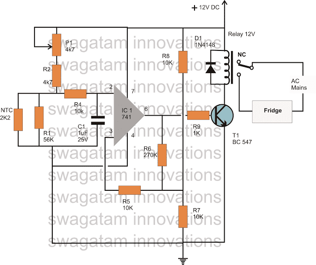
If you have any further questions regarding this Automatic Refrigerator Temperature Controller Circuit, you can express the same through your comments
Regulation of RP1, RP2 can be given points temperature control, 555 timing Schmitt inversion circuit using relays to achieve automatic control.

| Updated 01 Apr 2018. Created March 29, 2018 | |||||||||
Need for customization temperature regime occurs when used various systems thermal or refrigeration equipment. There are many options, and they all require a control device, without which the systems can operate either in maximum power, or at the full minimum of capabilities. Control and adjustment are carried out using a thermostat - a device that can influence the system through a temperature sensor and turn it on or off as needed. Using ready-made kits equipment, control units are included in the delivery package, but for homemade systems you have to assemble the thermostat yourself. The task is not the easiest, but quite solvable. Let's take a closer look at it.
The principle of operation of the thermostat
A thermostat is a device that can respond to changes in temperature. Based on the type of action, a distinction is made between trigger-type thermostats, which turn off or turn on heating when a specified limit is reached, or smooth-action devices with the ability to fine-tune and accurately adjust, capable of controlling temperature changes in the range of fractions of a degree.
There are two types of thermostats:
- Mechanical. It is a device that uses the principle of expansion of gases when temperature changes, or bimetallic plates that change their shape when heated or cooled.
- Electronic. It consists of a main unit and a temperature sensor that sends signals about an increase or decrease in the set temperature in the system. Used in systems requiring high sensitivity and fine adjustment.
Mechanical devices do not allow for high precision settings. They are both a temperature sensor and executive body, united into a single node. A bimetallic strip used in heating devices is a thermocouple made of two metals with different coefficients of thermal expansion.
The main purpose of the thermostat is to automatically maintain the required temperature
When heated, one of them becomes larger than the other, causing the plate to bend. The contacts installed on it open and stop heating. When cooled, the plate returns to its original shape, the contacts close again and heating resumes.
The chamber with the gas mixture is a sensitive element of the refrigerator thermostat or heating thermostat. When temperature changes, the volume of gas changes, which causes movement of the surface of the membrane connected to the lever of the contact group.
The thermostat for heating uses a chamber with a gas mixture that works according to Gay-Lussac's law - when the temperature changes, the volume of gas changes
Mechanical thermostats are reliable and provide stable operation, but the operating mode is adjusted with a large error, almost “by eye”. If fine tuning is necessary, providing adjustment within a few degrees (or even finer), electronic circuits are used. The temperature sensor for them is a thermistor, which is capable of distinguishing the smallest changes in the heating mode in the system. For electronic circuits, the situation is the opposite - the sensitivity of the sensor is too high and it is artificially coarsened, bringing it to the limits of reason. The principle of operation is a change in the resistance of the sensor caused by fluctuations in the temperature of the controlled environment. The circuit reacts to changes in signal parameters and increases/decreases heating in the system until another signal is received. The capabilities of electronic control units are much higher and allow you to obtain temperature settings of any accuracy. The sensitivity of such thermostats is even excessive, since heating and cooling are processes with high inertia, which slow down the reaction time to changing commands.
Scope of homemade device
Making a mechanical thermostat at home is quite difficult and irrational, since the result will operate in too wide a range and will not be able to provide the required adjustment accuracy. Most often, homemade electronic thermostats are assembled, which allow you to maintain optimal mode temperature of the heated floor, incubator, ensure the desired water temperature in the pool, heating the steam room in the sauna, etc. There can be as many options for using a homemade thermostat as there are systems in the house that need to be configured and adjusted. For rough adjustments using mechanical devices It’s easier to purchase ready-made elements; they are inexpensive and quite accessible.
Advantages and disadvantages
A homemade thermostat has certain advantages and disadvantages. The advantages of the device are:
- High maintainability. A thermostat made by yourself is easy to repair, since its design and operating principle are known to the smallest detail.
- The costs of creating a regulator are much lower than when purchasing a ready-made unit.
- It is possible to change the operating parameters to obtain a more suitable result.
The disadvantages include:
- Assembly of such a device is only available to people who have sufficient training and certain skills in working with electronic circuits and a soldering iron.
- The quality of operation of the device largely depends on the condition of the parts used.
- The assembled circuit requires adjustment and alignment on a control stand or using a reference sample. Receive immediately ready-made option device is not possible.
The main problem is the need for training or, at a minimum, the participation of a specialist in the process of creating the device.
How to make a simple thermostat
The manufacture of a thermostat occurs in stages:
- Selecting the type and circuit of the device.
- Acquisition necessary materials, tools and parts.
- Device assembly, configuration, commissioning.
The manufacturing stages of the device have their own characteristics, so they should be considered in more detail.
Necessary materials
Materials required for assembly include:
- Foil getinax or circuit board;
- Soldering iron with solder and rosin, ideally a soldering station;
- Tweezers;
- Pliers;
- Magnifier;
- Wire cutters;
- Insulating tape;
- Copper connecting wire;
- Necessary parts according to the electrical diagram.
Other tools or materials may be needed during the process, so this list should not be considered exhaustive or definitive.
Device diagrams
The choice of scheme is determined by the capabilities and level of training of the master. How more complicated scheme, the more nuances will arise when assembling and configuring the device. At the same time the most simple circuits make it possible to obtain only the most primitive instruments operating with a high error.
Let's consider one of the simple schemes.
In this circuit, a zener diode is used as a comparator
The figure on the left shows the regulator circuit, and on the right is the relay block that turns on the load. The temperature sensor is resistor R4, and R1 is a variable resistor used to adjust the heating mode. The control element is a zener diode TL431, which is open as long as there is a load on its control electrode above 2.5 V. Heating of the thermistor causes a decrease in resistance, causing the voltage on the control electrode to drop, the zener diode closes, cutting off the load.
The other scheme is somewhat more complicated. It uses a comparator - an element that compares the readings of the temperature sensor and reference source voltage.
A similar circuit with a comparator is applicable for adjusting the temperature of a heated floor.
Any change in voltage caused by an increase or decrease in the resistance of the thermistor creates a difference between the standard and the operating line of the circuit, as a result of which a signal is generated at the output of the device, causing the heating to turn on or off. Such schemes, in particular, are used to regulate the operating mode of heated floors.
Step-by-step instruction
The assembly procedure for each device has its own characteristics, but some general steps can be identified. Let's look at the build progress:
- We prepare the device body. This is important because the board cannot be left unprotected.
- We are preparing the payment. If you use foil getinax, you will have to etch the tracks using electrolytic methods, having first painted them with paint insoluble in the electrolyte. A circuit board with ready-made contacts greatly simplifies and speeds up the assembly process.
- Using a multimeter, we check the performance of the parts and, if necessary, replace them with serviceable samples.
- According to the diagram, we assemble and connect everything necessary details. It is necessary to ensure the accuracy of the connection, correct polarity and direction of installation of diodes or microcircuits. Any mistake can lead to failure important details which will have to be purchased again.
- After completing assembly, it is recommended to carefully inspect the board again, check the accuracy of the connections, the quality of soldering and other important points.
- The board is placed in the case and produced trial run and setting up the device.
How to setup
To configure the device, you must either have a reference device or know the voltage rating corresponding to a particular temperature of the controlled environment. Individual devices have their own formulas showing the dependence of the voltage on the comparator on temperature. For example, for the LM335 sensor this formula looks like:
V = (273 + T) 0.01,
where T is the required temperature in Celsius.
In other schemes, adjustment is made by selecting the values of adjusting resistors when creating a certain, known temperature. In each specific case, our own methods can be used, optimally suited to the existing conditions or equipment used. The requirements for the accuracy of the device also differ from each other, so in principle there is no single adjustment technology.
Basic faults
The most common malfunction of homemade thermostats is instability of the thermistor readings caused by poor quality parts. In addition, there are often difficulties with setting modes caused by mismatches in ratings or changes in the composition of parts required for proper operation devices. Majority possible problems directly depend on the level of training of the technician who assembles and configures the device, since skills and experience in this matter mean a lot. However, experts say that making a thermostat with your own hands is a useful practical task that gives good experience in creating electronic devices.
If you don’t have confidence in your abilities, it’s better to use a ready-made device, of which there are plenty on sale. It must be taken into account that a regulator failure at the most inopportune moment can cause serious troubles, the elimination of which will require effort, time and money. Therefore, when deciding on self-assembly, you should approach the issue as responsibly as possible and carefully weigh your options.