- System performance serving up to 4 rooms.
- Dimensions of air ducts and air distribution grilles.
- Resistance of the air network.
- Heater power and estimated energy costs (when using an electric heater).
If you need to choose a model with humidification, cooling or recovery, use the calculator on the Breezart website.
An example of calculating ventilation using a calculator
In this example we will show how to calculate the supply ventilation for 3 room apartment, in which a family of three lives (two adults and a child). Relatives sometimes come to visit them during the day, so the living room can long time stay up to 5 people. The ceiling height of the apartment is 2.8 meters. Room parameters:
We will set the consumption rates for the bedroom and nursery in accordance with the recommendations of SNiP - 60 m³/h per person. For the living room we will limit ourselves to 30 m³/h, since a large number of There are rarely people in this room. According to SNiP, such air flow is permissible for rooms with natural ventilation (you can open a window for ventilation). If we set the air flow rate of 60 m³/h per person for the living room, then the required productivity for this room would be 300 m³/h. The cost of electricity to heat this amount of air would be very high, so we made a compromise between comfort and efficiency. To calculate air exchange by multiplicity for all rooms, we will select a comfortable double air exchange.
The main air duct will be rectangular, rigid, and the branches will be flexible, sound-insulated (this combination of duct types is not the most common, but we chose it for demonstration purposes). For additional cleaning supply air A fine dust filter of class EU5 will be installed (we will calculate the network resistance with dirty filters). We will leave the air velocities in the air ducts and the permissible noise level on the grilles equal to the recommended values, which are set by default.
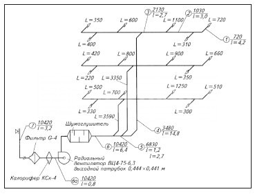
We begin the calculation by drawing up a diagram of the air distribution network. This diagram will allow us to determine the length of the air ducts and the number of turns that can be in both horizontal and vertical planes (we need to count all turns at right angles). So, our scheme:
The resistance of the air distribution network is equal to the resistance of the longest section. This section can be divided into two parts: the main air duct and the longest branch. If you have two branches of approximately the same length, then you need to determine which one has more resistance. To do this, we can assume that the resistance of one turn is equal to the resistance of 2.5 meters of the air duct, then the greatest resistance will be the branch whose value (2.5 * number of turns + length of the air duct) is maximum. It is necessary to select two parts from the route in order to be able to specify different type air ducts and different air speeds for the main section and branches.
In our system, balancing throttle valves are installed on all branches, allowing you to adjust the air flow in each room in accordance with the project. Their resistance (in the open state) is already taken into account, since this standard element ventilation system.
The length of the main air duct (from the air intake grille to the branch to room No. 1) is 15 meters; there are 4 turns at right angles in this section. Length air handling unit And air filter can be ignored (their resistance will be taken into account separately), and the resistance of the silencer can be taken equal to the resistance of the air duct of the same length, that is, simply consider it part of the main air duct. The longest branch is 7 meters long and has 3 right angle turns (one at the branch, one at the duct and one at the adapter). Thus, we have specified all the necessary initial data and can now begin calculations (screenshot). The calculation results are summarized in tables:
Calculation results for premisesResults of calculation of general parameters
| Ventilation system type | Regular | VAV |
| Performance | 365 m³/h | 243 m³/h |
| Cross-sectional area of the main air duct | 253 cm² | 169 cm² |
| Recommended dimensions of the main air duct | 160x160 mm 90x315 mm 125x250 mm |
125x140 mm 90x200 mm 140x140 mm |
| Air network resistance | 219 Pa | 228 Pa |
| Heater power | 5.40 kW | 3.59 kW |
| Recommended air supply installation | Breezart 550 Lux (in 550 m³/h configuration) |
Breezart 550 Lux (VAV) |
| Maximum performance recommended PU |
438 m³/h | 433 m³/h |
| Electric power heater PU | 4.8 kW | 4.8 kW |
| Average monthly energy costs | 2698 rubles | 1619 rubles |
Air duct network calculation
- For each room (subsection 1.2), the performance is calculated, the cross-section of the air duct is determined and a suitable air duct of standard diameter is selected. Using the Arktos catalog, the dimensions of distribution grilles with a given noise level are determined (data for the AMN, ADN, AMP, ADR series is used). You can use other grilles with the same dimensions - in this case, there may be a slight change in the noise level and network resistance. In our case, the grilles for all rooms turned out to be the same, since at a noise level of 25 dB(A) permissible flow rate air through them is 180 m³/h (there are no smaller grilles in these series).
- The sum of the air flow rates for all three rooms gives us the overall system performance (subsection 1.3). When using a VAV system, the system performance will be one third lower due to separate adjustment of air flow in each room. Next, the cross-section of the main air duct is calculated (in the right column - for a VAV system) and suitable sized air ducts are selected rectangular section(usually several options are given with different aspect ratios). At the end of the section, the resistance of the air network is calculated, which turns out to be quite large - this is due to the use of a fine filter in the ventilation system, which has a high resistance.
- We have received all the necessary data to complete the air distribution network, with the exception of the size of the main air duct between branches 1 and 3 (this parameter is not calculated in the calculator, since the network configuration is unknown in advance). However, the cross-sectional area of this section can be easily calculated manually: from the cross-sectional area of the main air duct, you need to subtract the cross-sectional area of branch No. 3. Having obtained the cross-sectional area of the air duct, its size can be determined by.
Calculation of heater power and selection of air handling unit
The recommended model Breezart 550 Lux has software-configurable parameters (performance and heater power), so the performance that should be selected when setting up the control unit is indicated in brackets. It can be noted that the maximum possible heater power of this unit is 11% lower than the calculated value. The lack of power will be noticeable only when the outside temperature is below -22°C, and this does not happen often. In such cases, the air handling unit will automatically switch to a lower speed to maintain the set outlet temperature (“Comfort” function).
The calculation results, in addition to the required performance of the ventilation system, indicate the maximum performance of the control unit at a given network resistance. If this performance turns out to be significantly higher than the required value, you can use the ability to programmatically limit the maximum performance, which is available for all Breezart ventilation units. For a VAV system, the maximum capacity is provided for reference only, as performance is adjusted automatically while the system is running.
Operating cost calculation
This section calculates the cost of electricity spent on heating air during the cold season. The costs for a VAV system depend on its configuration and operating mode, therefore they are assumed to be equal to the average value: 60% of the costs of a conventional ventilation system. In our case, you can save money by reducing air consumption in the living room at night and in the bedroom during the day.
|
|
|
|
From the author: Hello, dear readers! The ventilation system is a very important component of the design of any home. After all, it is thanks to her that you breathe fresh, not stale air. This has a significant positive influence both on the health of the people living in the house and on their level of comfort.
But all these advantages are relevant, of course, for those cases when it works correctly. In particular, its performance is very important, which must be sufficient for a particular building. To ensure the required performance, it is important to choose the right equipment required power, and also make a calculation of the cross-section of the ventilation duct.
Necessity of calculations
All calculations for arranging ventilation both in a private house and in an apartment must be carried out as carefully as possible. This is due to the fact that poor quality air exchange can lead to quite serious consequences. Among them are:
- discomfort of people living in the house. It's hard to be in a stuffy room. Besides, everything unpleasant odors stagnate because they simply don’t have a chance to get out. As a result, both furniture and room decoration are impregnated with them. It is clear that such a home does not evoke pleasant sensations;
- harm to health. Exhaust air contains large amounts carbon dioxide. If you stay in such an atmosphere for a long time, then this does not affect the body. in the best possible way. People get tired quickly and often get headaches. And the general state of health sooner or later deteriorates;
- increased humidity level. To regulate it, high-quality air exchange is necessary, and when with latest problems, the result becomes obvious. The consequence of this state of affairs is unpleasant condensation on the windows, and it is more difficult to breathe in a room with a high level of humidity than usual. In addition, this situation will lead to the appearance of mold and mildew on the walls. Getting rid of such “neighbors” is very, very difficult. But it’s impossible not to get rid of it - the spores released by mold get into the lungs of people living in the house. This provokes the development of various infections, some of which are life-threatening.
Carrying out calculations

Now that you are convinced of the extreme necessity of calculations, we can talk about how they are made. But first of all, it’s worth understanding what factors influence the final indicator. Actually, they all refer to the type of duct itself.
Types of air ducts
Air ducts differ in two parameters. The first is the material from which this structural element is made. There are quite a lot modern options. Air ducts can be:
- steel (ferrous or stainless metal);
- plastic;
- aluminum;
- fabric;
- tin.
Wherein important has a material structure. The rougher the surface inside the pipe, the more force the air has to exert to travel along the appropriate route, as resistance increases. This factor directly affects the required cross-sectional index.
The second parameter is the shape of the duct. It can be round, square, oval or rectangular. Each form has certain advantages and disadvantages. For example, round varieties require less material for manufacturing, which is beneficial from an economic point of view. Rectangular air ducts may not be too large both in height and width - all the same, their cross-sectional area will be kept at the required level.
Calculation methods
Strictly speaking, the calculations necessary for the arrangement of other types of ventilation should be carried out by specialized organizations that have the appropriate license. Professionals have a full range of necessary knowledge and experience. It is often difficult for an ordinary person to understand how to correctly calculate this or that parameter.
But the desire for economy and love for independent work have not gone away, so many still prefer to understand this issue. If you belong to this category of people, then be patient and have a notepad and pen.
For calculation cross section There are two ways to duct. One is based on permissible velocities, the other is based on constant pressure loss. Both of them give the necessary parameter, but the first one is simpler. So it's better to start with it.
All buildings and premises are divided into different categories. Depending on the type of building, a certain standardized value of the maximum permissible speed is provided for it, both for the main air duct and for the branches coming from it.

Accordingly, you will need these standard indicators to make calculations. You also need to have a plan on hand indicating all the routes included and the types of equipment installed. It is on these blanks that the further work process will be based.
As for the standardized indicators of the maximum permissible speed, they can be summarized in the following list:
- production premises - for the main line the permissible speed is from 6 to 11 meters per second, for branches from 4 to 9 meters per second;
- office premises - for the main highway from 3.5 to 6 m/s, for branches from 3 to 6.5 m/s;
- residential premises - for the main line from 3.5 to 5 m/s, for branches from 3 to 5 m/s.
These standards are due to the fact that an air flow speed that exceeds them will create high level noise that will make people in the room very uncomfortable.
So, the calculation process comes down to the following steps.
- A diagram of the ventilation system is drawn up. It indicates each highway and its branches. It also identifies all equipment that is installed in the air ducts. This includes diffusers, valves, grilles and the like. All duct turns should also be marked.
- Next, you need to calculate how much air should enter the room every hour. This parameter depends primarily on the number of people in the room for a long time. The volume of air for each person is approved by SNiP standards. They indicate that in a room where natural ventilation is not carried out, the air flow per person is at least 60 m 3 / h. If we are talking about the bedroom, then the figure is lower - only 30 m 3 / h. This is due to the fact that during sleep a person processes less oxygen. In general, to calculate it is necessary to take into account the number of people staying in the house for a long time, and multiply this number by the indicator established by the standards. If you have regular meetings big companies, then there is no need to rely on them - the standards are relevant only for long-term stays. In such a case, you can get a VAV system that will help regulate air exchange processes between rooms when receiving guests.
- Once you have received both indicators - that is, the maximum permissible speed and the required volume of air entering the room - you can begin to calculate the estimated area of the air duct. To do this, you can use a diagram called a nomogram. As a rule, it comes complete with flexible pipe air duct. If it is not in paper form, then you can search on the website of the company that produced this product. In addition to the nomogram, you can calculate the required indicator manually. To do this, you need to substitute the available parameters into the formula: Sc=L*2.778/V. By Sc we mean, in fact, the same area of the air duct. It will be expressed in square centimeters, since this value is most convenient to work with. The letter L means the previously calculated required volume of air entering the room through the air duct. The letter V is the speed of air flow in a particular line. The number 2.778 is the coefficient required for matching various types units of measurement: m 3 / h, m / s and cm 2.
- Now you can begin to calculate the actual cross-sectional area of the duct. There are two formulas for this. Which one to use depends on the shape of the pipe. For a round duct: S=π*D²/400. By S we mean the calculated cross-sectional area, and by D we mean the diameter of the pipe. For rectangular version the formula is as follows: S=A*B/100. In this case, the letter A means the width of the pipe, and the letter B means the height. The dimensions of the sides of the rectangle and the diameter of the circle are indicated in millimeters.
Thus, it is necessary to calculate the corresponding indicator for each section of the ventilation system: both for the main routes and for additional routes. Based on these indicators, you can proceed to the calculation required power equipment installed for forced air inflow or outflow.

To correctly select a built-in fan, you will also need to know the pressure drop in the ventilation system. This parameter can be calculated using the same nomogram that you used to determine the volume of air.
Dear readers! All the calculations necessary for arranging any type of ventilation system are, in principle, not that complicated. But they require quite a lot of time, as well as careful attention. A miscalculation may lead to you installing an air duct that is too narrow or wide, or selecting ventilation equipment with a power that does not meet the needs of the room.
Therefore, if you are not confident in your abilities or are firmly aware of existing problems with physics and mathematics, then it is better to turn to specialists. This will not hit the budget too hard, but in return will provide a guarantee that the ventilation system will work with proper functionality.
If you are still determined to independent conduct calculations, then also watch the video instructions, the link to which is left below. Approach the matter carefully and carefully, then everything will work out great for you. Good luck to you, comfort to your home! See you again!
If the ventilation in a house or apartment does not cope with its tasks, then this is fraught with very serious consequences. Yes, problems in the operation of this system do not appear as quickly and sensitively as, say, problems with heating, and not all owners pay adequate attention to them. But the results can be very sad. This is stale, waterlogged indoor air, that is, an ideal environment for the development of pathogens. These are foggy windows and damp walls, on which pockets of mold may soon appear. Finally, this is simply a decrease in comfort due to odors spreading from the bathroom, bathroom, kitchen into the living area.
To avoid stagnation, air must be exchanged at a certain frequency in the premises over a period of time. The inflow is carried out through the living area of the apartment or house, the exhaust through the kitchen, bathroom, toilet. This is why windows (vents) of exhaust ventilation ducts are located there. Often, homeowners who are undertaking renovations ask whether it is possible to seal up these vents or reduce them in size in order, for example, to install certain pieces of furniture on the walls. So, it is definitely impossible to completely block them, but transfer or change in size is possible, but not only with the condition that the necessary performance will be ensured, that is, the ability to pass the required volume of air. How can we determine this? We hope that the following calculators for calculating the cross-sectional area of an exhaust ventilation vent will help the reader.
Calculators will be accompanied by the necessary explanations for performing the calculations.
Calculation of normal air exchange for effective ventilation of an apartment or house
So, when normal operation ventilation, the air in the rooms must be constantly changed within an hour. The current governing documents (SNiP and SanPiN) establish inflow standards fresh air into each of the premises of the residential area of the apartment, as well as the minimum volumes of its exhaust through channels located in the kitchen, in the bathroom, and sometimes in some other special rooms.
| Room type | Minimum air exchange rates (multiplicity per hour or cubic meters per hour) | |
|---|---|---|
| INFLOW | HOOD | |
| Requirements for the Code of Rules SP 55.13330.2011 to SNiP 31-02-2001 “Single-apartment residential buildings” | ||
| Residential premises with permanent occupancy | At least one volume exchange per hour | - |
| Kitchen | - | 60 m³/hour |
| Bathroom, toilet | - | 25 m³/hour |
| Other premises | At least 0.2 volumes per hour | |
| Requirements for the Code of Rules SP 60.13330.2012 to SNiP 41-01-2003 “Heating, ventilation and air conditioning” | ||
| Minimum outdoor air flow per person: residential premises with constant occupancy, under natural ventilation conditions: | ||
| With a total living area of more than 20 m² per person | 30 m³/hour, but not less than 0.35 of the total air exchange volume of the apartment per hour | |
| With a total living area of less than 20 m² per person | 3 m³/hour for every 1 m² of room area | |
| Requirements for the Code of Rules SP 54.13330.2011 to SNiP 31-01-2003 “Residential multi-apartment buildings”
|
||
| Bedroom, children's room, living room | One-time volume exchange per hour | |
| Office, library | 0.5 of volume per hour | |
| Linen room, pantry, dressing room | 0.2 of volume per hour | |
| Home gym, billiard room | 80 m³/hour | |
| Kitchen with electric stove | 60 m³/hour | |
| Premises with gas equipment | One-time exchange + 100 m³/hour for a gas stove | |
| Room with solid fuel boiler or oven | One-time exchange + 100 m³/hour for a boiler or furnace | |
| Home laundry, dryer, ironing | 90 m³/hour | |
| Shower, bath, toilet or combined bathroom | 25 m³/hour | |
| Home sauna | 10 m³/hour per person | |
An inquisitive reader will probably notice that the standards for different documents are somewhat different. Moreover, in one case the standards are established solely by the size (volume) of the room, and in the other - by the number of people constantly staying in this room. (The concept of permanent stay means staying in the room for 2 hours or more).
Therefore, when carrying out calculations, it is advisable to calculate the minimum volume of air exchange according to all available standards. And then choose the result with the maximum indicator - then there will definitely be no errors.
The first calculator offered will help you quickly and accurately calculate the air flow for all rooms of an apartment or house.
Calculator for calculating the required air flow volumes for normal ventilation
Creation comfortable conditions staying in the premises is impossible without an aerodynamic calculation of the air ducts. Based on the data obtained, the cross-sectional diameter of the pipes, the power of the fans, the number and features of the branches are determined. Additionally, the power of heaters and the parameters of inlet and outlet openings can be calculated. Depending on the specific purpose of the rooms, the maximum permissible noise level, air exchange rate, direction and speed of flows in the room are taken into account.
Modern requirements are specified in the Code of Rules SP 60.13330.2012. Normalized parameters of indoor microclimate indicators for various purposes given in GOST 30494, SanPiN 2.1.3.2630, SanPiN 2.4.1.1249 and SanPiN 2.1.2.2645. During calculation of indicators ventilation systems all provisions must be mandatory be taken into account.
Aerodynamic calculation of air ducts - algorithm of actions
The work includes several successive stages, each of which solves local problems. The obtained data is formatted in the form of tables, and based on them, schematic diagrams and graphs are drawn up. The work is divided into the following stages:
- Development of an axonometric diagram of air distribution throughout the system. Based on the diagram, a specific calculation methodology is determined, taking into account the features and tasks of the ventilation system.
- An aerodynamic calculation of air ducts is performed both along the main routes and all branches.
- Based on the data received, it is selected geometric shape and cross-sectional area of the air ducts are determined technical specifications fans and heaters. Additionally, the possibility of installing fire extinguishing sensors, preventing the spread of smoke, and the possibility of automatic adjustment ventilation power taking into account the program compiled by the users.
Development of a ventilation system diagram
Depending on the linear parameters of the diagram, the scale is selected, the diagram indicates the spatial position of the air ducts, the connection points of additional technical devices, existing branches, air supply and intake points.

The diagram indicates the main line, its location and parameters, connection points and technical characteristics of the branches. The location of air ducts takes into account the architectural characteristics of the premises and the building as a whole. When drawing up a supply circuit, the calculation procedure begins from the point furthest from the fan or from the room for which the maximum air exchange rate is required. During compilation exhaust ventilation The main criterion is the maximum air flow rate. During calculations, the general line is divided into separate sections, and each section must have the same cross-sections of air ducts, stable air consumption, the same manufacturing materials and pipe geometry.

The segments are numbered in sequence from the section with the lowest flow rate and in increasing order to the highest. Next, the actual length of each individual section is determined, the individual sections are summed up, and the total length of the ventilation system is determined.
When planning a ventilation scheme, they can be taken as common for the following premises:
- residential or public in any combination;
- industrial, if they belong to group A or B according to the fire safety category and are located on no more than three floors;
- one of the categories of industrial buildings categories B1 - B4;
- category industrial buildings B1 m B2 are allowed to be connected to one ventilation system in any combination.
If the ventilation systems completely lack the possibility of natural ventilation, then the diagram must provide for the mandatory connection of emergency equipment. The power and installation location of additional fans are calculated according to general rules. For rooms that have openings that are constantly open or open when necessary, the diagram can be drawn up without the possibility of a backup emergency connection.
Systems for suctioning contaminated air directly from technological or work areas must have one backup fan; turning the device into operation can be automatic or manual. The requirements apply to work areas of hazard classes 1 and 2. It is allowed not to include a backup fan in the installation diagram only in the following cases:
- Synchronized stop of harmful production processes in case of malfunction of the ventilation system.
- The production premises have a separate emergency ventilation with their own air ducts. Such ventilation parameters must remove at least 10% of the volume of air provided by stationary systems.
The ventilation scheme must provide a separate possibility of showering on workplace with increased levels of air pollution. All sections and connection points are indicated on the diagram and included in the general calculation algorithm.
It is prohibited to place air receiving devices closer than eight meters horizontally from garbage dumps, car parking areas, roads with heavy traffic, exhaust pipes and chimneys. Receptionists air devices subject to protection special devices on the windward side. Resistance indicators protective devices taken into account during aerodynamic calculations common system ventilation.
Calculation of air flow pressure loss Aerodynamic calculation of air ducts based on air losses is done with the aim of the right choice sections to meet the technical requirements of the system and select fan power. Losses are determined by the formula:

R yd is the value of specific pressure losses in all sections of the air duct;
P gr – gravitational air pressure in vertical channels;
Σ l – the sum of individual sections of the ventilation system.
Pressure losses are obtained in Pa, the length of sections is determined in meters. If the movement of air flows in ventilation systems occurs due to natural pressure differences, then the calculated pressure reduction Σ = (Rln + Z) for each separate area. To calculate the gravitational pressure you need to use the formula:
P gr – gravitational pressure, Pa;
h – height of the air column, m;
ρ n – air density outside the room, kg/m3;
ρ in – indoor air density, kg/m3.
Further calculations for natural ventilation systems are performed using the formulas:
Determining the cross-section of air ducts
Determining driving speed air masses in gas ducts
Calculation of losses based on local resistances of the ventilation system
Determination of friction loss
Determination of air flow speed in channels
The calculation begins with the longest and most remote section of the ventilation system. As a result of aerodynamic calculations of air ducts, the required ventilation mode in the room must be ensured.

The cross-sectional area is determined by the formula:
F P = L P /V T .
F P – cross-sectional area of the air channel;
L P – actual air flow in the calculated section of the ventilation system;
V T – speed of air flow to ensure the required frequency of air exchange in the required volume.
Taking into account the results obtained, the pressure loss during the forced movement of air masses through the air ducts is determined.


For each air duct material, correction factors are applied, depending on the surface roughness indicators and the speed of movement of air flows. To facilitate aerodynamic calculations of air ducts, you can use tables.
Table No. 1. Calculation of metal air ducts of round profile.


Table No. 2. Values of correction factors taking into account the material of air ducts and air flow speed.

The roughness coefficients used for calculations for each material depend not only on its physical characteristics, but also on the speed of air flow. The faster the air moves, the more resistance it experiences. This feature must be taken into account when selecting a specific coefficient.
Aerodynamic calculations for air flow in square and round air ducts show different flow rates for the same cross-sectional area of the nominal bore. This is explained by differences in the nature of vortices, their meaning and ability to resist movement.
The main condition for calculations is that the speed of air movement constantly increases as the area approaches the fan. Taking this into account, requirements are imposed on the diameters of the channels. In this case, the parameters of air exchange in the premises must be taken into account. The locations of the inflow and outlet flows are selected in such a way that people staying in the room do not feel drafts. If it is not possible to achieve the regulated result with a straight section, then diaphragms with through holes. By changing the diameter of the holes, optimal regulation of air flow is achieved. The diaphragm resistance is calculated using the formula:

The general calculation of ventilation systems should take into account:
- Dynamic air pressure during movement. The data is consistent with terms of reference and serve as the main criterion when choosing a specific fan, its location and operating principle. If it is impossible to ensure the planned operating modes of the ventilation system with one unit, installation of several is provided. The specific location of their installation depends on the features schematic diagram air ducts and permissible parameters.
- The volume (flow rate) of transported air masses in the context of each branch and room per unit of time. Initial data - requirements of sanitary authorities for cleanliness of the premises and features technological process industrial enterprises.
- Unavoidable pressure losses resulting from vortex phenomena during the movement of air flows at various speeds. In addition to this parameter, the actual cross-section of the air duct and its geometric shape are taken into account.
- Optimal air movement speed in the main channel and separately for each branch. The indicator influences the choice of fan power and their installation locations.
To facilitate calculations, it is allowed to use a simplified scheme; it is used for all premises with non-critical requirements. To guarantee the required parameters, the selection of fans in terms of power and quantity is done with a margin of up to 15%. Simplified aerodynamic calculations of ventilation systems are performed using the following algorithm:
- Determination of the cross-sectional area of the channel depending on the optimal speed of air flow.
- Selecting a standard channel cross-section close to the design one. Specific indicators should always be selected upward. Air channels may have increased technical indicators; it is prohibited to reduce their capabilities. If it is impossible to select standard channels in technical conditions It is envisaged that they will be manufactured according to individual sketches.
- Checking air speed indicators taking into account the actual values of the conventional cross-section of the main channel and all branches.
The task of aerodynamic calculation of air ducts is to ensure the planned ventilation rates of premises with minimal losses of financial resources. At the same time, it is necessary to strive to reduce the labor intensity and metal consumption of construction and installation work, to ensure the reliable operation of the installed equipment in various modes.
Special equipment must be installed in accessible places, with unhindered access to it for routine technical inspections and other work to maintain the system in working order.
According to the provisions of GOST R EN 13779-2007 for calculating ventilation efficiency ε v you need to apply the formula:

with ENA– indicators of the concentration of harmful compounds and suspended substances in the removed air;
With IDA– concentration of harmful chemical compounds and suspended substances in the room or work area;
c sup– indicators of contaminants entering with the supply air.
The efficiency of ventilation systems depends not only on the power of the connected exhaust or blower devices, but also on the location of the sources of air pollution. During aerodynamic calculations, the minimum performance indicators of the system must be taken into account.
Specific power (P Sfp > W∙s / m 3) of fans is calculated using the formula:

de P – power electric motor, installed on the fan, W;
q v – air flow rate supplied by the fans during optimal operation, m 3 /s;
∆ p – indicator of the pressure drop at the air inlet and outlet of the fan;
η tot – total coefficient useful action for electric motor, air fan and air ducts.
During calculations we mean following types air flows according to the numbering in the diagram:
Diagram 1. Types of air flows in the ventilation system.

- External, enters the air conditioning system from the external environment.
- Supply. Air flows entering the duct system after preliminary preparation(heating or cleaning).
- The air in the room.
- Flowing air currents. Air moving from one room to another.
- Exhaust. Air exhausted from the room to the outside or into the system.
- Recirculation. The portion of the flow returned to the system to maintain the internal temperature within the specified values.
- Removable. Air that is removed from the premises irrevocably.
- Secondary air. Returned back to the room after cleaning, heating, cooling, etc.
- Air loss. Possible leaks due to leaky air duct connections.
- Infiltration. The process of air entering indoors naturally.
- Exfiltration. Natural air leakage from the room.
- Air mixture. Simultaneous suppression of multiple threads.
Each type of air has its own state standards. All calculations of ventilation systems must take them into account.