The woodworking machine is used not only in carpentry or industrial workshops. Using this device on the farm, it is possible to independently produce any piece of furniture and even build a house. Let's look at how to make woodworking machines with your own hands below.
Woodworking machine structure
Each woodworking machine consists of main and additional parts. The main parts are:
- work plate,
- bed,
- shaft device,
- one of the cutting tool options,
- mechanism responsible for transmitting motion.

Additional elements of a woodworking machine:
- areas with fencing of dangerous places,
- point responsible for supplying wooden material,
- device for starting the machine,
- lubrication device.
A heavy structure made of cast iron or solid steel alloy is used as a frame. All structural parts of the machine are installed on the bed. It is responsible for their location and for the stability of the device. In most cases, the frame is installed on a reinforced concrete foundation.
The main function of the desktop is to capture all work items. It is made from pre-polished cast iron. There are two table options: movable and fixed.
To attach the cutting tool to the machine, a working shaft device is used. There are several varieties of this device, which differ in the type of cutting tool attached to it. Highlight:
- saw,
- knife,
- spindle working shaft.
It is always made of turned steel, characterized by strength, balance and the presence of a place on which the cutting tool is attached.

Various parts act as cutting tools. They differ in design and functional features, as well as shape and size.
High quality carbon steel is used for their manufacture. Let's look at some types of cutting tools for a woodworking machine:
- a device in the form of a round disk is used on circular saw machines;
- a tool in the form of a saw blade is used on band saw machines;
- flat and shaped knives are used on milling, planing or tenoning structures;
- Drills are used on woodworking drilling machines;
- the slotting chain is used on chain slotting devices;
- for milling and tenoning machines, an excellent option would be to use hooks, slotting discs and cutters;
- on woodworking machines of scraping type, scraping knives are used;
- Rolled sandpaper is used for sanding machines.
Woodworking machines photo:

Advantages and scope of use of woodworking machines
Woodworking machines have a large number of advantages over hand tools on processing wooden surfaces. Firstly, the operating speed of a woodworking machine is much higher, so using this machine significantly saves time on processing one part.
A universal woodworking machine is capable of processing various parts and performs several types of work, such as sanding, milling and drilling.
If all manufacturing technologies for a woodworking machine are followed, such a device can serve its owner for decades.
Modern CNC woodworking machines have improved operating functions, during which the person working on the machine practically does not overwork. It is enough to launch a pre-recorded program and install the part. At this rate, the number of parts is increasing, and the time for processing them is decreasing. Such machines are capable of working around the clock and continuously.
If we consider woodworking machines for household use, there are also many advantages among them:
1. Such machines are equipped with a motor with an average power of 2.2 kW, this power allows you to perform work quickly and without overloading.

2. Such machines have good quality of processed products.
3. They do not require high maintenance and operation costs.
4. The ability to install additional attachments allows you to increase the number of functions of a household woodworking machine.
5. The main functions of such a machine are sawing, sanding, milling and drilling wood.
6. A large number of functions and the versatility of such equipment allows you to work with various types wood, while performing various operations.
7. If we look at reviews of woodworking machines, then for private or home use An excellent option would be to buy or make a household machine yourself.
The scope of use of woodworking machines is quite wide due to their versatility. They are used in both private and industrial woodworking.
Woodworking machines are used to produce semi-fabricated elements or blanks, such as boards, bars, veneer, and shavings. They also produce parts for wooden products or entire wooden structures, for example: parquet, flooring, furniture, parts of musical instruments, etc.
All tasks associated with wood processing are easily solved by a woodworking machine. This device not only saws and drills wood, but also grinds it and even carves, which takes tens of times more time to do manually.

Main types of woodworking machines
In relation to the technological principle of wood processing, woodworking machines are divided into:
- universal,
- specialized,
- narrow production.
Universal machines are widely popular due to their versatility. They are used in a variety of industrial and individual enterprises. The peculiarity of this machine is that it can perform almost all types of wood processing. But at the same time, the quality of the work performed will be slightly lower than, for example, with a specialized machine.
Specialized woodworking machines are capable of performing only one function, while being able to be reconfigured and used in different industries.
The use of special machines is limited to the manufacture of certain parts; other operations cannot be performed on such a machine.
Specialized machines are:
- milling type,
- circular saw type,
- band saw type,
- longitudinal milling type,
- drill type,
- tenon type,
- drilling and milling type,
- turning type,
- slotting type,
- grinding type.

One of the main types of wood processing is milling machines, which perform the functions:
- milling parts in various directions,
- shaped production of parts,
- cuttings of extraordinary elements,
- making grooves.
Milling woodworking machines are divided into:
- devices of a simple type, which are single- and double-spindle;
- copying machines - engaged in the production of small parts based on the use of complex technologies;
- Rotary machines perform flat and shaped processing.
Tabletop woodworking machines are also distinguished, which in turn are divided into:
- vertical type machines,
- horizontal type,
- longitudinal type,
- highly specialized type.
Lathes - work with different types wood from soft to hardwood. They are equipped with a copying device that produces similar parts. The scope of use is not limited to art workshops. Lathes produce parts of various shapes: conical, cylindrical.

Lathes are divided into:
- center - they are supplied with tools mechanized or manually, which can be cut, designed for the manufacture of similar parts;
- lobotovarny - make model parts;
- round rod - produce products in which the diameter varies along the length of the part.
Circular saw type woodworking machines perform longitudinal, angular and cross cutting. There are manual and mechanized ones.
Reaming machines plan boards on a flat slope. There are:
- one-sided,
- double-sided,
- multi-knife.
To determine the type or type of woodworking machine, there are special designations. The first one or two letters indicate the type according to the principle of operation, and the next ones - technological properties machine To find out the number of working elements on a node, there are numbers between these letters.
In relation to the accuracy of processing the part, woodworking machines are distinguished:
- first class (O) - indicating very high processing accuracy;
- second class (P) - accuracy is eleven or twelve qualifications;
- third class (C) - with an accuracy of thirteen to fifteen qualifications;
- fourth class (N) - with reduced accuracy.

Homemade woodworking machines - manufacturing instructions
To make a universal woodworking machine you will need:
- electric motor,
- shaft,
- drill chuck,
- bed, which is height adjustable.
This device will easily sharpen, sand and cut wooden parts.
When choosing an engine, pay attention to the following parameters:
- synchronicity,
- power in the range from 0.6 to 1.5 kW,
- the average shaft rotation speed per minute is 2500 revolutions.
The shaft must have a device for attaching a drill chuck. If it is missing, you need to sharpen the end part of the shaft using a file. The diameter of the fastening should be slightly larger than the diameter of the cartridge. Then turn on the engine and sharpen the chuck so that it is secured to the shaft. Using a file and lapping paste, adjust the chuck to the size of the shaft. If such paste is not available, you should rub sandpaper and dilute its abrasive with oil.
In the central part of the shaft, a hole should be drilled and a thread M5 M6 should be cut, in order to protect the cartridge from accidental slipping, it should be fixed using a countersunk head.
The standard layout of the machine allows you to place wooden part in different positions relative to the machine.

Woodworking machine drawings:
The table is fastened to the frame using two bolts, and the slats are fastened using fixing brackets.
To construct the frame, you will need six metal corners with a cross-section of 2.5x2.5 cm, and one corner with a cross-section of 4x4 cm. Their length is 30 cm. To connect, use welding machine. Keep an eye on quality welding seams, since the machine constantly vibrates during operation.
To make a tabletop, you can use plastic, metal, boards or plywood.
To install the parts on the table space, you will need to make a strip and bracket. To install a pulley, cutter or saw into the chuck hole, you must additionally make adapter bushings and mandrels.
A simplified version of manufacturing a woodworking machine
The manufacture of a woodworking machine must begin with its functional purpose; the fewer functions the device performs, the easier it is to build.
To make a frame, take a metal corner or pipe. Weld a strong frame, and then strengthen it with additional corners to reduce the level of vibration of the structure.
It is better to install the frame in a certain place and concrete it into the floor.
The next stage is the construction or purchase of a woodworking shaft, which has a width of 30 cm, which can accommodate several knives at once.
To build a table, use strong and smooth steel, about 1 cm thick. To adjust the planing thickness, make folding table, consisting of two separate parts. This way the height of one part will be adjustable. In this case, the second part requires rigid fixation.
For the engine, take a device with a power of 2 to 5 kW, with a rotation speed of 2000 to 3000 rpm. If the speed is lower, this will affect the quality of the machine.
Install the engine on the frame. Pull the belts and make a moving angle that will help you adjust the length of sawing of the part. Install another corner that will align the position of the workpiece in relation to the cutting tool.
Processing of wood blanks is carried out on a special turning equipment. Using a device of this type allows you to perform various operations with high precision. If necessary, you can make a wood lathe with your own hands. This will save money. To manufacture this device, you must familiarize yourself with its design features and take advantage of expert advice.
This unit includes several main components. Each of them performs a specific function. To make a homemade device, you will need to become more familiar with the structure of these elements.

Bed. The basis of any machine, including woodworking. This unit ensures the stability of the structure for work surface and also promotes fixation individual elements machine Thanks to the frame, all components are located in the right places.
It's important to remember that stationary devices They have a larger frame equipped with legs. In turn, desktop units have a more compact base, which makes them mobile. When making a woodworking machine with your own hands, you need to pay attention Special attention this unit, since the accuracy and efficiency of the structure as a whole depends on it.
Headstock. This unit performs a very important function: it ensures the rotation of the wooden block during its processing. The workpiece is fixed in a chuck located in the spindle shaft. It is worth noting that some small-sized machines include a headstock that can move along the guides of the base (bed). Its movement allows you to adjust the location of individual parts relative to each other.
When the part is being machined, the headstock of the lathe is securely secured. Models that are classified as stationary often combine this element with a frame, which makes it completely motionless.

Tailstock. This unit, which is part of the woodworking structure, is not static. It performs a very important function: it fixes the blank in the desired position during processing. Securing the workpiece by means of the rear assembly takes into account its pressing against the chuck. Due to the fact that the tailstock is able to move freely along the guide elements of the frame, fixing and processing of parts is ensured different lengths.
Note! The tailstock must be in line with the spindle shaft.
Caliper. A very important design element, thanks to which the movement of the cutter is realized. Moreover, the latter may have a different location in relation to the spindle. In most homemade devices of this type this function performed by a tool rest securely fastened in the working position.
This part of the machine is capable of moving along the guides of the base (bed). Small-sized desktop devices, as a rule, imply the use of an element such as a stop for incisors.

Thus, both a serial and a home-made machine is a rather complex design. Any wood processing unit includes several interconnected units. Before you make a wood lathe with your own hands, you need to clearly understand the purpose of its components.
How to make a wood lathe: making the bed
In serial devices, the frame is in most cases made of cast iron. This material is distinguished by its mass. For a homemade unit, you should choose a less heavy option. For example, as the basis for a future design, you can choose angles made of rolled angle steel. The recommended length of the segments is 125 cm.
The length of the bed can be increased, but this action will require intervention in other parts of the woodworking unit. Before making it, it is recommended to draw up a plan on paper. You can also take a ready-made drawing from the specialized website that will help you assemble a wood lathe with your own hands.
Let us consider step by step the algorithm of actions for the manufacture of this unit. First of all, you need to place the corresponding corners on a horizontal surface (open side to each other). Then it is recommended to place calibrated inserts between them, which will allow you to maintain the required distance of 4.5 cm.

Next you need to connect the guides. For these purposes, the same corners are most often used, differing only in size (19 cm). It is recommended to mark the points at which welding will be performed in advance. The jumpers are located near the edges of the long corners. On next stage The welding itself is carried out.
Helpful information! The bed of any homemade woodworking machine is the basis of the structure, so its installation is very important. Any violation in the future will affect the efficiency and accuracy of the unit, made by hand.
Then you need to attach another jumper of the same size. It should have cutouts for long corners. After installing this part, a cell should be formed for the headstock tenon. The dimensions of this geometric element require precise adherence. To install a standard headstock tenon, 4.5 x 16.5 cm is sufficient.
DIY woodworking machine: how to make a handy
Traditionally, this part includes two components. They are made from steel corners. Standard dimensions of workpieces for welding – 5 and 3 cm. The joining of these elements is done by welding (in length). The result is two segments, which should have a length of 26 and 60 cm.

Tool rest on a lathe - needed for support when working with wood
The short element is used as a customizable support base. Moreover, one of the corner shelves must be cut at an angle so that 11 cm of the untouched profile remains. Before performing the same manipulation on the other wing, it is necessary to step back from the edge by 6 cm. The angle itself in the second case remains straight.
Next, you need to make a counter frame for a homemade woodworking machine. A steel plate is suitable for the manufacture of this element. The next step is to make the guide element and its clamp. As a material for these purposes, you can use a regular inch pipe. You need to make a longitudinal slot in it using a grinder. Craftsmen advise not to make this part longer than 15 cm.
Then the guide sleeve is installed in a 2.5 cm corner. The cut made with a grinder should be perpendicular to one of the shelves. Next, the structure must be fixed in a clamp and connected using welding equipment. After this, the tube is covered with a second corner and connected to it in the same way.
The finished guide part is joined by welding to the protruding flange of the angle. For final fastening, it is necessary to weld a nut to the rail, and equip the second part with a screw. Also, do not forget that with reverse side it is necessary to perform additional fixation of the structure. To do this, you can weld a metal rod to its individual parts. It will give the structure strength and rigidity.

The tool rest is fixed on a piece of reinforcement (smooth), which should have a diameter of 2 cm. Such a rod is fixed on the back side of the corner approximately in its center. At the end, it is necessary to connect the reinforcement to a long part (60 cm).
Homemade lathefor wood: selecting a drive
The drive must have sufficient power to handle wooden products. When purchasing this device, it is advisable to pay attention to the standard models. Their power varies from 1200 to 2000 watts. This is quite enough for processing various kinds of parts at home. The most commonly used drive is a power rating of 1200 watts.
Induction motors are often used in homemade wood lathes. It is not possible to make this device with your own hands. Another characteristic that is common among drives installed on machine tools self-made, – three-phase.
Note! When assembling such equipment at home, it is quite difficult to purchase an engine that would have the required rotation speed. However, if desired, this indicator can be adjusted by changing the diameter of the pulleys.

When installing the drive, it is recommended to equip the frame with a special plate. It is fixed on the gate canopies and ensures a tighter pressing of the strap. Some craftsmen install a pedal on the platform, which allows them to change the number of revolutions per second while processing a wooden block.
DIY lathe: headstock and tailstock
To manufacture these components, you must have access to a metalworking machine. If this is not possible, it is recommended to purchase ready-made structural elements. The headstock of a woodworking unit includes two housings that belong to the bearing category.
When assembling the machine yourself, it is important to remember that the height of the spindle axis above the base must be no less than 12 cm. This indicator affects the size of the front unit. The most suitable in this situation is a bearing block with a height of 7 cm. The shaft itself can be made on a metalworking device. Its diameter should not be less than 4 cm.
In turn, the procedure for making the tailstock of a wood lathe with your own hands is less complicated. This module includes 4 elements, including:
- base;

- guide (external);
- inner tube;
- drive screw.
It is recommended to make the base from a steel angle, the height of which should not exceed 10 cm. To create a guide, you can use a tube measuring 4x15 cm. In its rear part, you must install a special plug with a hole (0.8 cm). In this case, the inner tube will have dimensions of 2 cm. Next, you need to make a drive screw. A thread is applied to it for the nut in the inner tube.
It is also worth noting that the headstock and tailstock should be on the same line. Otherwise, further construction of a woodworking machine will not bring any results. The headstocks are fixed to the bed in the same way as the tool rest.
Making cutters for a wood lathe with your own hands
If necessary, these functional elements can be purchased at a specialized store or ordered online. However, many craftsmen prefer to make these devices themselves. The most popular cutting elements today are Reyer and Meisel. They are quite simple to perform on a sharpening machine.

In order to make these cutting elements, you will need a blank. You can use old tools (for example, a file) as it. The metalworking unit allows you to sharpen this blank quite quickly. Forming is performed at two points: where the blade will be located and the tail.
Related article:
Review of popular models of woodworking machines. Tips for selection and rules of use.

The next step in making a wood cutter with your own hands is stuffing a turned handle with a locking ring. In this way, you can independently produce cutters for a woodworking unit.
Note! As the initial material for making these functional elements, you can use not only files, but also rasps or fittings.
It is also important to remember that a homemade tool must first be tested on soft wood. Such a check will determine how well the cutter is made and whether it is advisable to use it when working with hard rocks.
Wood turning and milling machinewith your own hands
From a design point of view, serial units of this type are quite complex. This is due to the fact that they are equipped with CNC. It is impossible to recreate such a system at home, so experts recommend making the simplest possible milling units.

When manufacturing such a unit, it is not recommended to use classic version, in which the blank is located between the front and rear nodes. It is also advisable to abandon the functional part represented by the cutter. In this case, the functional element will be a manual router. The advantages of this design are its economy and increased functionality.
Turning and milling equipment used to process wood includes several components. You can do them yourself. First you need to make the base of the unit (bed). For its manufacture, as a rule, wooden blocks are used. This type of support is characterized by high strength and rigidity.
Then the front node is fixed, which should not move. The tailstock, on the contrary, must change its position by moving along the mounting panel.

When swinging an electric motor, one common method is used to increase its efficiency. A disk of smaller diameter is mounted on the drive shaft, and a larger one is mounted on a similar element of the front assembly. The interaction in this case is carried out by means of a belt drive.
As mentioned above, in this case, the tool for turning wood is a milling cutter. It is mounted at the top support point on a self-made platform. It is important to remember that homemade devices exclude the possibility of connecting a functional element to the CNC. Thus, it is in this order that the simplest unit with a cutter, equipped to the minimum, is manufactured.
Do-it-yourself wood lathe with a copier
A copier is a device that allows you to make carvings on a workpiece according to a given template. Thanks to it, it becomes possible to produce similar parts at high speed. Copying machine woodworking allows you to avoid painstaking work and is most often used in home workshops.
For self-made The copying element can be taken as a basis with a manual router. It must be placed on a plywood board, the thickness of which should not be more than 1.2 cm. The standard dimensions for such a workpiece are 20x50 cm.

Helpful information! The productivity of a wood milling and copying machine allows it to be used not only at home, but also in small industries.
Then you need to drill holes for the fastening elements, as well as install small bars that will serve as supports for the functional part. Next, the cutter must be placed between the clamps and secured using ordinary self-tapping screws. After this, all that remains is to place the block (7x3 cm) on the machine. It is used to attach the stencil.
This is how you make your own wood lathe with a copier. Videos that allow you to clearly understand this issue can be viewed on the Internet. Making this device is not that difficult. All work comes down to a simple modernization of a conventional unit.
DIY mini wood lathe
A smaller device can also be made in a home workshop. A DIY mini wood lathe has a size of 20 to 30 cm. In order to make it, you will need an old motor and a power supply from an unnecessary Soviet-style radio. This small device is perfect for turning small wooden parts (for example, handles).

This device can also be used as a mini metal lathe. With your own hands, it is not difficult to make such a small device that will allow you to give the desired shape not only to wooden blanks, but also to products made of tin and even aluminum.
In this case, there is a certain algorithm of actions that should be followed. First of all, you need to take a metal sheet and prepare a box that will serve as a case for the engine. Experts recommend choosing sheets with a thickness of 1-1.5 mm. The plate must be bent in the shape of the letter “P” and a hole must be made in it for the shaft.
Next, you need to make several elements from a wooden block at once. The thickness of the material should be approximately 2-3 cm. First, the supporting casing is made, and then the supporting parts for the motor and rear assembly.
The next step is to cut square pieces of wood and glue them together into a “tower”. Then you need to secure the resulting structure using self-tapping screws (4 pcs.). In the end, all that remains is to mark the point of the holder, the function of which is performed by a self-tapping screw, and fix the faceplate on the engine side.

Such instructions allow you to make a small machine, the dimensions of which will not exceed 25 cm. Of course, such a device is not suitable for serious work. But for performing small tasks such a device is the most suitable option, which is very easy to assemble with your own hands. A mini lathe consumes very little electrical energy, which is also a plus.
Do-it-yourself wood lathe using a drill
If you have a workbench in your workshop, then the process of manufacturing a woodworking unit is greatly simplified. In this situation, there is no need to search for materials for the frame or to assemble it directly. Replace turning device A regular drill fixed on a flat, horizontal surface of a workbench is capable.
Helpful information! The drill performs several functions at once, which on a regular machine fall on the front assembly, as well as the rotation drive.
The drill is fixed using a clamp and a clamp, which must be secured to the neck of the electronic tool. However, the remaining components necessary for processing wooden blanks still have to be assembled.

First of all, this concerns the tailstock, which acts as a stop. This unit is fixed parallel to the drill and, as a rule, is made of wooden blocks. For reliability, it is also recommended to use an adjustment screw, the head of which is sharpened to a cone.
Further assembly of the lathe from a drill is quite simple. The support can be replaced with an ordinary wooden block, which is fixed on a horizontal plane using a clamp.
The main rule when assembling such a simple structure is to ensure alignment of the spindle rotation axis and the adjustment screw on the rear assembly. For example, you can temporarily assemble a lathe from an ordinary drill. Moreover, on such a machine you can both perform wood processing and produce blanks from soft metals (aluminum, copper, etc.).
Rules for using a homemade wood lathe
Experts recommend studying training materials that will help you understand the operational nuances of a DIY wood lathe. Videos on this topic can be easily found on the Internet.

It would also be useful to consider the basic rules that should be followed when working on such equipment. Each of them must be completed without fail. For example, before you start processing a workpiece, you need to make sure that it is suitable for this. The blank should not have knots, cracks or deformations of the wood.
Placing the workpiece also requires following a certain procedure. Fixation is carried out using special fasteners, which are placed on the shaft of the front unit and on the rear bar.
Separately, it is worth mentioning that the processing accuracy is influenced by the rotation speed of the blank. Speed regulation is carried out by changing the position of the drive belt in the pulley channels. The process of processing a wooden blank requires care. It is recommended to take measurements of a product turned using a functional element.
During work, you must not forget about overalls. Goggles are used to protect the eyes from chips and dust. And also before starting work, it is necessary to check the serviceability of individual elements of equipment.

The machine must only be operated by someone who is familiar with its operation, technical maintenance and warned about possible dangers
The answer to the question of how to make a wood lathe at home will allow you to save money. Self-assembly This unit requires preliminary calculations, drawing up a diagram, and care. Compliance with the instructions is the basic rule that must be followed when constructing such a device. Homemade unit can be a useful addition to any home workshop.
We will tell you how to make relatively simple woodworking machines and accessories for them with your own hands, using available tools and materials, as well as the basic operations for technical wood processing.
As a parting word, I would like to give you some advice and wishes: when you take the path of technical creativity, arm yourself with patience and perseverance; balance your desires with the available opportunities; use simple techniques, available tools and materials; Don't give up at the first failures. Success will definitely come to you!
Latest publications on the site
ELECTRIC MOTORS
The heart of the machine’s electric drive is deservedly the electric motor (EM). The number of their series, types, and specific designs is difficult to count, much less describe. But, it seems, this information is of no use to the home craftsman: after all, he has access to a very limited range of EDs, usually installed in household appliances and cars. They arouse his increased interest. He most often uses them in his designs. We will talk about them.
Since DC motors have limited use in everyday life, with the exception of drive mechanisms for toys, portable tape recorders and other small-sized devices, we will not dwell on them. We only note that DC motors of appropriate power are used in mobile vehicles, for example, on airplanes, ships, etc., where they can be powered from the on-board network, as well as in various industrial equipment due to their high efficiency, stepless speed control and others positive qualities. Such electric motors are connected to the alternating current network through special rectifiers.
But commutator AC motors, despite their rather complex design, are very widely used in everyday life, since they have many positive qualities.
The excitation winding of such an electric motor is connected in series with the armature winding, due to which, when the direction of the current in the network changes, it simultaneously changes
This is the direction of the current in the armature and the polarity of the poles. The direction of the torque is maintained.
The motor rotation frequency does not depend on the frequency of the current in the network and can be very significant. This circumstance allows the use of commutator motors in vacuum cleaners, fans and other devices where a high rotation speed of the working body is dictated by necessity. These motors retain the basic characteristics characteristic of DC collector motors and are used where a large starting torque is needed (polishing machines, meat grinders, food processors, etc.). Due to the high rotation speed, such a motor is characterized by a high specific power per unit weight and is lightweight, which is very important for electrified hand tools and other portable devices. The advantage of these engines is their ability to withstand short-term overloads. Their operation is not disrupted even with significant voltage fluctuations in the supply network. The current strength when starting such motors, as a rule, does not exceed four times the rated value, so they operate stably in the mode of frequent starts and shutdowns.
The collector ED can be made for low supply voltage and for lighting network voltage. It can operate on direct and alternating current, changing only the nominal data depending on the type of current. To ensure that these data are approximately the same, the EM excitation winding is made with an additional output. When operating from direct current, all turns of these coils are turned on, and when operating on alternating current, only part of them is turned on. Such an engine is called universal.
The advantage of a collector EM is that it is easy to smoothly control the rotation speed within the widest limits, as well as reversing (changing the direction of rotation). To do this, it is enough just to change the direction of the current in the armature winding or field winding, swapping their ends.
Unfortunately, single-phase commutator motors are not without weaknesses. They are complex and expensive to manufacture, require qualified maintenance,
constant maintenance of brushes and commutators require special filters to suppress interference to radio reception. To give a more specific idea of collector electric motors, let us turn to LPC type motors, which are found in many manual electrical machines(saws, planes, drills, jigsaws, etc.) and are structurally connected with them, i.e. they are built-in.
They are double insulated, which greatly increases the safety of working with them. Their power is 120–1150 W, armature rotation speed is 12000–18000 min1. They are directly powered by AC and DC power, without requiring bulky transformers or electrical frequency converters.
The stator of the LPC motor, mounted in a plastic case, consists of a package of steel plates, in the cutouts of which two electromagnet coils are installed, passing through which the electric current creates a constant magnetic flux.
The rotor consists of a steel package, in the grooves of which the winding is laid. Its terminals are connected to the collector. The shaft, with a rotor, a collector and a fan mounted on it, rotates on two ball bearings. One of them is mounted in the socket of the rear wall of the case, and the other - in the socket of the intermediate shield.
The fan is used to cool the engine during operation. Air is sucked in through the inlet windows in the casing, cools the stator winding and is pushed out through the windows of the intermediate shield into the atmosphere.
The brushes are placed in a special holder and pressed against the commutator by springs. Electrical current is supplied to the brushes through two wires connected to a two-pole switch.
The radio interference suppression filter is mounted on the rear wall of the engine housing and covered with a casing. As already mentioned, commutator motors can be used to drive light milling, drilling, sharpening, lathes and other homemade structures. They work especially successfully with power devices that allow you to regulate their rotation speed and also reduce the temperature of the case.
This is most easily achieved using an adjustable laboratory autotransformer (LATRA). The engine can also be connected to the network through an autotransformer, which allows you to obtain several fixed output voltages. Unfortunately, such devices are not commercially available. But if you wish, you can make an autotransformer yourself. To do this, you should select a magnetic core with a cross-section of 16–20 cm2 (for example, ШЛ 32 x 50), wind a winding of 400 turns of 1.5 mm PEV2 wire. Make bends from 230, 270 and 320 turns. Connect the lead from the beginning of the winding to one terminal, and all the rest to other terminals located around the first one. By shorting the beginning of the winding alternately with its other terminals, you can obtain a series of alternating current voltages needed to power the motor.
Thyristor voltage regulators are even more convenient, allowing smooth regulation of the motor rotation speed. Similar devices are commercially available. If necessary, you can make such a regulator yourself. Quite a few of their schemes were published in the magazine “Radio”, on the pages of the “Mass Radio Library” and other similar publications. For the most part, such devices allow you to regulate the voltage on the active load in the range from 0 to 220 V. The load power also varies in a wide range from several W to 1.5 kW or more. With their help, you can obtain direct current and power it with universal commutator motors, as well as DC motors. To do this, you need to include an electrolytic capacitor of the appropriate capacity and the required operating voltage in the rectifier circuit of the thyristor voltage regulator and connect its leads to the load.
Behind last years began to produce hand-held drilling machines (drills) with small-sized electronic units management. They can also be used to power autonomous commutator motors of appropriate power. Collector EDs built into homemade machines(especially closed type), it is advisable to cool intensively. For example, small-sized fans from personal computers are very convenient for this.
Inexperienced readers should be warned against using high-speed motors without appropriate gearboxes and other speed controllers in most home-made woodworking machines, with the exception of milling machines.
Another tip: in cases where you need to free up both hands for work and, at the same time, often turn on and off a machine that uses a commutator motor, there is no better assistant than a foot switch. It consists of a wooden base, inside which a push-button switch of any type is mounted. The pedal is bent from sheet metal. It is attached to the base with two screws, which simultaneously serve as an axis of rotation. So that the pedal can independently occupy the upper position, it is spring-loaded (a piece of foam rubber, a rubber tube, an elastic metal plate or a cylindrical spring is placed under it). Wires with a socket and plug are brought out from the switch for connection to the electrical network and the engine. A reliable design is also obtained from a single-key network switch. It must be screwed to a wooden base, and elastic material must be placed under the key.
Single-phase asynchronous motors are widely used in various household appliances. They are structurally different from collector ones and have tangible advantages over them: they do not interfere with radio reception, they are much simpler in design, which means they are cheap and reliable, and do not require high operating costs. The principle of operation of such an emf is that the emf in the rotor winding is induced by an alternating magnetic field. Therefore, there is no need to supply current to it from an energy source, and therefore, there is no need for sliding contacts in the form of brushes and a commutator. Moreover, since the rotor winding is not connected to the power source, it may not be isolated from the rotor core itself. If you hammer copper or aluminum rods into its grooves, the current will flow through them, and not through the steel sheets from which the core is made, since they have significantly lower electrical resistance.
However, when connected directly to the network, such a motor will not rotate due to the absence of a rotating magnetic field. Therefore, numerous types of self-starting EDs have been developed.
The most widely used are single-phase asynchronous motors with starting windings. These windings are not concentrated in the form of coils, as in DC motors, but are evenly distributed in the stator slots. The working winding remains connected to the network for the entire operating time of the electric motor, and the starting winding is turned on only while the rotor is moving away and turns off when the engine reaches the required number of revolutions. In the starting winding circuit there is a starting element, most often in the form of an active resistance or capacitor. The motor can be easily reversed by swapping the lead ends of the working or starting windings.
There are motors in which the starting resistance is contained in the starting winding itself. These include single-phase electric motors of the AOLB series, which have satisfactory starting and operating characteristics.
EDs with starting capacitors have higher starting properties. These include, in particular, the DOLG series engines. In an electric motor with a starting winding, after it is turned off, 1/3 of the stator slots remain unused, so it has a reduced net power. To increase it, they began to use motors in which the starting winding remains connected to the network through a capacitor all the time. Such an electric motor is called capacitor, and its starting winding is called auxiliary. This engine has many positive operating properties: more power on the shaft, high efficiency and increased power factor. But, unfortunately, it has rather low starting characteristics. To improve them, they began to include an additional so-called starting capacitor in parallel with the working capacitor during the start-up of the electric motor. This engine was given the designation AOLD.
Later they began to produce capacitor electric motors of the ABE series, which have better performance characteristics compared to their predecessors.
Currently, single-phase capacitor motors of increased power are produced, reaching up to 1.3 kW. They are, in particular, widely used in household woodworking machines produced by industry.
Many motors used in household electrical appliances can be successfully used to drive various home-made machines. As a rule, they should be connected to the network with the same starting and protective equipment with which they were installed in household machines.
To give readers an idea of the electrical equipment of a modern desktop woodworking machine that uses a capacitor motor, we present its electrical circuit diagram (Fig. 62).
The engine is protected from overloads by thermal relay KK1, which breaks the starting network of the KM1 starter. Restarting is possible only after 15–20 s, i.e. after the thermal protection elements of the KK1 relay return to their original position. The increase in starting torque when starting the electric motor occurs due to connection C, parallel to C2. Frequent starts of it are unacceptable, since it will be turned off by a thermal relay. The electrical circuit provides zero protection, which is carried out by opening the block contacts of the KM1 starter when the voltage in the self-supply circuit disappears magnetic starter and in the motor starting winding circuit.
So far we have been talking about single-phase electric motors. This is natural, since single-phase current is widely used in our country among individual consumers. However, with the emergence of small private enterprises in the city and countryside, and a huge number of gardening partnerships, the situation has changed dramatically in recent years. To intensify labor in such farms, the need arose for more powerful electrified machines and tools with three-phase motors, and a more extensive network to power them.
Home craftsmen, of course, do not remain aloof from these changes; many of them are already widely using them. This is explained by the fact that three-phase asynchronous squirrel-cage motors have many undeniable advantages: simplicity, reliability, compactness, low cost, economical maintenance, and the ability to maintain an almost constant rotation speed when the load changes. Their power is essentially limited only by the wiring parameters. They do not require bulky and expensive capacitors. True, such engines have their own weaknesses: low ability to overload, reduced reliability when 
work with frequent starts and stops, etc. Nevertheless, these disadvantages do not detract from the advantages of three-phase motors.
How does such an engine work? Its stator consists of a package of electrical steel sheets, in the grooves of which a three-phase winding is laid. The rotor is also assembled from a package steel sheets. It has a winding of aluminum rods running through its slots and short-circuited at the ends in rings. Hence the engine received the name squirrel-cage. The rotor is mounted on the shaft along with the fan. The shaft rotates on two ball bearings. The stator windings have six ends and can be connected to each other according to an established star or triangle pattern (Fig. 63). In the first case, the beginnings or ends of all three phases converge at one point, and the remaining three terminals are connected to a three-phase network. In the second option, the end of the first phase is connected to the beginning of the second, the end of the second - to the beginning of the third, and the end of the third -
with the beginning of the first. A three-phase network is connected to their connection points.
Typically, the winding terminal clamps are placed on the motor block in a certain order. In this case, a star connection is achieved with a horizontal connection, and a triangle connection with a vertical arrangement of jumpers (Fig. 63). The connection option for the ends of the stator windings is chosen depending on the voltage in the network (most often it is 220 or 380 V). If the engine must operate from a 220 V network, then the output ends of the windings are connected in a triangle, and from a 380 V network - in a star. Reversing a three-phase EM occurs if any two phase wires are swapped. Electric current is usually supplied to a three-phase motor by a four-core cable, one of the cores of which serves to connect to the motor housing.
Asynchronous three-phase motors are connected to a three-phase network most often according to the generally accepted scheme 
(Fig. 64). Magnetic starters, circuit breakers and fuses are used as protective and starting equipment.
However, some home craftsmen, due to the lack of such equipment, connect the engine directly to the network. At the risk of incapacitating him, they still get out of the situation. This can be done if there is a fuse and subject to constant monitoring of the operating motor in order to immediately turn it off if there is a smell of overheated winding insulation or the appearance of unusual sounds made by the engine.
In practice, there are often cases when it is necessary to use a three-phase motor in a single-phase network. And they do this, despite the fact that in this case it does not have a starting torque and cannot start on its own. Therefore, they resort to various “tricks”. For example, it is known that if the rotor of an engine is moved, it begins to rotate. This is how an ED is sometimes launched, i.e. by hand or with the help of a rope wound around a shaft. Unfortunately, this method is far from the best: it is very dangerous, and the power of the electric motor in this case is small, amounting to only 50% or less than the nominal one. In addition, this option for starting an electric motor is generally unacceptable for powerful drives.
Three-phase motor in single-phase connection It is incomparably better to use with capacitors, since this increases its power factor, which can acquire values almost equal to unity. However, it should be borne in mind that the capacitances of the starting and operating capacitors at a certain network voltage and the adopted circuit for switching on the electric motor depend on its power. As its capacitance increases, it also increases, reaching a reasonable limit when the use of capacitors becomes economically unprofitable due to the increase in their cost and weight. The maximum power of a capacitor motor is considered to be a rated power of 1.5 kW, indicated on its plate. Schematic diagrams of a capacitor motor with three windings on the stator are shown in Fig. 65. 
As in the case of three-phase connection, the stator windings can be connected in a star (Fig. 65 a) or triangle (Fig. 65 b). The mains voltage is supplied to two motor terminals corresponding to the beginnings of two phases. Between one of them and the output corresponding to the beginning of the third phase, capacitors 1 and 2 are switched on. The latter, as soon as the electric motor picks up speed, is turned off, and only capacitor 1 remains in the circuit. In these circuits, three combinations of the formation of input (network) terminals are possible: C1 - C2; C1 - NW; NW - C2.
Switching one of them to another leads to a change in rotor rotation (reversal).
In two other variants of switching circuits (Fig. 65 c, d), two windings are formed from the three phases of the original motor. One of them consists of two phases connected in series. In the circuit of the other winding there are working and starting capacitors.
Very great importance has the correct choice of working capacity. It is considered optimal if the phase currents and voltages under load become almost nominal. This capacitance is proportional to the motor power (rated current) and inversely proportional to the voltage. In relation to the considered circuits for switching on a capacitor motor for a network frequency of 50 Hz, the capacitance of the working capacitor can be approximately determined by the following relationships:
for the diagram in Fig. 65 a - Average ~ 2800 (J HOM/U); for the diagram in Fig. 65 b - Average ~ 4800 (Jhom /U); for the diagram in Fig. 65 v - Average ~ 1600 (JH0M/U); for the diagram in Fig. 65 g - Cnom ~ 2740 (JHOM/U);
where J ti - rated current, A; U - network voltage, V;
With a known motor power, the current consumed by it can be determined by the expression:
J = P/(1.73 Uncos(p);
where P is engine power (W); U - network voltage (V); cos f - power factor; c - efficiency indicated on its plate.
With the most common triangle connection of the motor windings in a 220 V network, the working capacitance (in microns) can be found using the formula:
Av = 66 Rn, where R is the rated power of the electric motor, kW.
Sometimes, for people who are not experienced in electrical engineering, it is recommended to carry out a simplified calculation when choosing the capacity of a working capacitor: for every 100 W of engine power, install about 7 microns of capacitor capacity. One can agree with a certain assumption with such a mnemonic rule.
When determining the starting capacity, one proceeds primarily from the requirement to create the necessary starting torque. If, due to the operating conditions of the electric drive, the engine starts without load, then this capacity is often taken equal to the working capacity. When starting under load, it is usually calculated using the expressions: Sp « (2...3) Wed; Sp = 132 pH or determined experimentally.
No less important is the selection of capacitors according to their operating voltage, and the latter can be determined using the following relationships:
for the diagram in Fig. 65 a and b - UK ~ 1.15 U;
for the diagram in Fig. 65 V - U„„ ~ 2.2 U;
K. r
for the diagram in Fig. 65 g - UK ~ 1.3 U; where UK is the design voltage of the capacitor.
It is considered correctly selected if its rated AC voltage is equal to or slightly greater than the rated voltage. From the above relationships it follows that when the engine is turned on according to the circuit (Fig. 65 c), the operating voltage of the capacitors should be almost twice as high as in other circuits. This feature must be taken into account in practice.
What types of capacitors are recommended to be used as working and starting capacitors?
For such purposes, paper and metal-paper capacitors are most often used: KBG - MN; BGT, MBGO, MBGP, MBGCH. You need to know that on all these capacitors, except for MBGC, the rated voltage for direct current is indicated, and reliable operation They are achieved with alternating current by choosing a voltage reserve of two or more times. Capacitors only
MBCGs are designed to operate in alternating current circuits. Therefore, they are selected according to the voltage closest to or greater than the phase voltage.
Capacitors built into network luminaires with fluorescent lamps can also be used along with MBGCh capacitors.
All of the above types of capacitors are used as starting capacitors. Often, in order to reduce the cost, volume and weight of the capacitance, electrolytic capacitors of the K5019 type or, better yet, EP, specially designed for operation in alternating current circuits, and, in extreme cases, KE2N are used; K503 and others with a margin of rated voltage. All electrolytic capacitors allow connection to the network for a duration of no more than 3 s. They cannot be used as workers, since in alternating current circuits they quickly heat up and fail, even exploding. It must be remembered that starting capacitors, after being disconnected from the network, retain voltage at their terminals for a long time, creating a danger of injury if touched. electric shock. This danger is higher the higher the capacity and voltage in the network. When repairing and debugging the engine, the capacitor should be discharged after each shutdown, or better yet, a resistor with a resistance of 68–75 kOhm and a power of 2 W should be soldered in parallel to it.
A few words about the installation of capacitors. It is advisable to place them in a durable, dust-proof casing made of dielectric material and fasten them to the base with metal strips placed in polyvinyl chloride tubes. Capacitors are usually connected to each other with tinned wire passed through the holes of the output petals. In this case, the soldering joints are not destroyed due to machine vibration. Conclusions are made with multi-colored wires.
Some readers, of course, are interested in the question: which of the considered schemes for connecting a three-phase motor to single-phase network preferable? Before answering this, let us first note characteristics each of them.
So, the diagram shown in Fig. 65 a, is characterized by a relatively small starting torque and voltage on the capacitor. A low starting torque is also inherent in the circuit in Fig. 65 b. Advantages of the circuits in Fig. 65 v and d - the ability to achieve significant starting torque and better use of engine power.
It seems that everything is simple, choose the scheme that you like. But it turns out that you can’t do this arbitrarily. The connection circuit is determined taking into account the network voltage and the motor voltage data. It will be selected correctly if any of the stator windings at rated load is under a voltage equal to or close to the rated one. In other words, the phase voltage of a three-phase motor when connected to a single-phase network must be preserved.
It is known that many three-phase electric motors are designed for two linear voltages, for example 127/220 V or 220/380 V. At a lower voltage of the electrical network, their winding is connected in a triangle, and at a higher voltage - in a star. It follows that if the supply network has a voltage of 220 V, then the ED, made for a voltage of 220/380 V, is switched on according to the diagram in Fig. 65 in; the motor for voltage 127/220 V in this case can be switched on according to the diagram in Fig. 65 a. Only in a 127 V network it is connected according to the diagram in Fig. 65 b.
Many older motors have six terminals on the terminals. Nowadays, electric motors are increasingly found in which the stator windings are tightly connected by a star or triangle and only three terminals (the beginning of the phases) are connected to the terminal block. In the latter case, you can disassemble the ED, disconnect the interphase connections and make three additional conclusions. Sometimes they do it differently: a motor designed for a voltage of 220 V with three terminals and a stator winding connected in a star is connected to a single-phase network with a voltage of 220 V according to the diagram in Fig. 65 a, and the same electric motor with a winding connected in a triangle, according to the diagram in Fig. 65 b. Considering that when starting a three-phase motor, the starting current exceeds the rated current by 4–8 times, in some cases
reducing it by switching the stator windings from a delta circuit to a star circuit. This is done using a special switch.
One of the features of operating a motor in a single-phase network is overheating of its windings both during prolonged overload and during prolonged underload. This is explained by the fact that in the first case the initially calculated working capacity turns out to be too small, and in the second - too large. Therefore, they try to avoid such cases, achieving optimal engine operation.
One way to improve the performance properties of a capacitor motor is to use an automatically controlled capacitance. Unfortunately, such devices are quite complex, expensive, and therefore difficult to use in everyday life. Using for these purposes a working capacitance, consisting of several sections of capacitors connected to the motor using conventional toggle switches, is also not justified: just forget to switch them in time, taking into account the expected load on the motor, and it will be damaged as a result of overheating of the windings. In circuits for switching on a capacitor motor, conventional control and protection equipment is used: switches, buttons, relays, fuses, etc. To give an idea of this, we present a typical circuit diagram electrical diagram a machine in which a three-phase electric motor is used, powered by a single-phase alternating current network with a voltage of 220 V, a frequency of 50 Hz (Fig. 66).
The engine is started and stopped using the KV relay, which controls the SB2 (Start) and SB1 (Stop) buttons. When starting, the KV relay turns on and becomes self-powered, connecting the ED to the network with its contacts and providing zero protection, i.e., turning it off in the absence of voltage in the network. The motor is protected from overload by relay A, which breaks the starting circuit, turning off the KV relay. Restarting is possible only after the thermal protection elements of relay A have returned to their original position.
An increase in the starting torque of the electric motor occurs due to the connection of capacitor C1 by the contacts of relay A 
parallel to working C2. After acceleration of the motor, capacitor C1 is turned off. Short circuit protection is provided by the FU fuse. The engine is reversed using the SA switch, which, in the middle position, ensures that the electric motor is disconnected from the network. As is clear from the above, a wide variety of electric motors are used in everyday life. In order not to “get lost” in them, to be able to choose the right one taking into account a specific electric drive, special knowledge is required.
In particular, information about the marking of the terminals of their windings helps to navigate more successfully in the whole variety of electrical machines. For example, in DC motors, the ends of the windings brought out are marked with the letters: I - armature winding, K - compensation winding, D - additional poles, S - series excitation, W - parallel excitation, N - independent excitation, P - starting, U - equalizing winding . Numbers are added to the letter designations: 1 - the beginning of the winding, 2 - its end. The windings of AC machines are in most cases located on the stator, so their terminals are designated by the letter C. Beginnings of the 1st, 2nd and 3rd phases three-phase winding are labeled C1, C2, SZ, respectively, and the ends of these phases when open circuit- C4, C5, Sat. The phase terminals of the windings of multi-speed asynchronous motors are additionally designated in front by numbers indicating the number of poles of the winding, for example 4С1, 4С2, 4СЗ.
The terminals of the stator windings of single-phase asynchronous machines are marked with the letter C, and the excitation windings with the letter I.
For asynchronous single-phase motors, this marking looks like this: C1 is the beginning of the main and B1 is the beginning of the auxiliary windings, and C2 and B2 are their ends, respectively. Terminal markings are applied to the terminal block next to them or directly to the output wires.
In small machines, where it is difficult to mark letters and numbers due to lack of space, the lead ends are made in different colors. Thus, in three-phase asynchronous EDs, the beginnings of the 1st, 2nd, and 3rd phases are shown in yellow, green and red, respectively. The ends of the phases with six terminals have the same colors, but with the addition of black. The zero point when connecting phases in a star is black. The terminals of the delta-connected winding are the same color as the beginning of the phases in an open circuit.
In single-phase asynchronous machines, the beginnings of the windings are designated: the main one by red, the auxiliary by blue, and their ends by the same color as the beginnings, but with the addition of black. With three outputs, the common point is indicated in black.
In small commutator machines of direct and alternating current, the beginnings of the windings are marked with the following colors: armatures - white, parallel excitation - green. At their ends, black is added to the indicated colors.
As for choosing a motor for a specific machine drive, this matter is not as simple as it might seem at first glance. Ideally, the engine should meet the requirements placed on it in literally all respects. Of course, achieving such an ideal is almost impossible, but you need to strive for it. Before we talk about this, we will provide some more background information.
It is known that ED, like any products, are produced in accordance with established requirements. For example, their rated powers, ranging from several watts to hundreds of kilowatts, have a strict gradation, the so-called series. This series for low-power electric machines looks like this: 0.06; 0.09; 0.12; 0.18; 0.25; 0.37; 0.55; 0.75; 1.1; 1.5; 2.2; 3.0 kW. And the series of synchronous engine speeds at a network frequency of 50 Hz has the following values: 500; 750; 1000; 1500 and 3000 min1. Three-phase asynchronous motors are currently produced with rated voltages and stator winding connection diagrams according to the data contained in Table. 9.
When choosing a motor, first of all, it is taken into account that it must ensure that the necessary operations on the machine are performed with the least expenditure of electrical energy.
Table 9 Therefore, despite the known direct dependence of the engine efficiency on its power, the use of an overpowered electric motor is considered unjustified. During operation, being underloaded, it will be used with low efficiency. On the other hand, an electric motor of insufficient power will not provide adequate machine performance; In addition, it will be overloaded and quickly overheat. Thus, when choosing ED by power, you should stick to the golden mean and determine its value with the greatest possible accuracy.
As for the voltage for which the engine should be designed, I think everything is clear: the local power grid dictates its conditions. A single-phase network, as a rule, has a voltage of 220 V, and a three-phase network - 220/380 V. This means that the motors must correspond to it. In this case, the still found single-phase electric motors with a voltage of 127 V can be powered through transformers and autotransformers, and three-phase electric motors with a voltage of 127/220 V can be connected to the network according to the diagrams given earlier.
It is also important that the engine rotor speed be as close as possible to the speed of the working body to which it is connected. In this case, preference should be given to high-speed EDs, since they usually have best characteristics, smaller dimensions and weight, lower cost.
Considering that many woodworking operations are performed with cutting tool rotation speeds of the order of 3000 min1, the engine rotor must rotate at the same frequency. Low-speed EDs do not justify themselves in this case. The fact is that at low speeds, circular saws, cutters, and planing knives cut wood poorly and with low productivity. An increase in their speed is associated with such a reduction in drive mechanisms (pulleys, belts), in which a gain in speed inevitably leads to a loss in oil. As a result, the engine starts poorly and stops at light load. In relation to the main operations performed on machine tools, we can recommend the rotation speeds of the working bodies as indicated in Table. 10.
240
Table 10 Rotation speed of working bodies during various operations An important characteristic of the engine is its starting torque. He should always be there more torque starting the machine spindle, and the acceleration time of the machine did not exceed 15–17 s.
Naturally, when they are looking for the right engine, then pay attention to it design, mounting method, dimensions, possibility of placement in the machine drive, etc. Motors are available on feet, with feet and a flange shield, or with only a flange. In each case, they clarify how best to secure it. The fastening must be reliable, sufficiently rigid and at the same time allow adjustment of the position of the EM and free access to it during maintenance and repair. The selected motor is checked by heating its housing so that the maximum temperature rise of the stator winding over the ambient temperature does not exceed the established limits. Otherwise, they try to improve its cooling; if necessary, use an additional fan. Temperature outer surface Most engines should not exceed 65°C. In practice, it is determined by the palm applied to its body: if the hand overheats, it cannot withstand such a touch.
Based on the above, we can recommend single-phase for the Universal1 machine asynchronous motor with capacitor starting power 1.1 kW and frequency
rotor rotation 3000 min1, and for three-phase network- three-phase ZD with the same data. In desktop small-sized designs it is permissible to use low-power motors of different types and characteristics.
The machine uses a purchased gasoline engine UD2-M-1, a three-phase electric motor (2.2 kW at 1500 rpm) and a purchased jointing shaft.
Since the most popular ones are on sale different designs planing shafts (with different sizes), the dimensions of the used shaft are not given. The same remark should be made regarding the nodes used when creating the machine. The author, an electrician by profession, works in an organization servicing an agricultural complex. For this reason, for example, handles from electric switches are used in the machine.
A noticeable structural difference between this woodworking machine and industrial designs is that the main working plane (table) is not made as usual - from a massive steel plate (10 mm thick or more), but is a prefabricated structure welded from corners and sheet metal (relatively thin ) coatings.
The main idea of the layout was to place the main components so that working on the machine was safe and convenient. For example, “safety bars” protect rotating machine parts from workpieces falling off tables. And the belt drive is hidden inside the body.
The overall dimensions of the machine depend on: - the purchased shaft and the size of the engines. The basis of the design of the machine (Fig. 1) is a frame welded from 50x50 mm corners. For ease of dismantling the gas engine, the left part of the frame is made removable and secured with M10 bolts.
Rice. 1 Universal woodworking machine with electric and petrol engines
The belt drive (Fig. 2) ensures operation with an electric drive and a gasoline engine. The tensioner allows the use of belts of different lengths: from 1000 to 1400 mm.

Rice. 2. Belt transmission scheme for gear shifting of electric and gasoline engines.
The main workflow when working on a machine is planing (jointing). The design of the corresponding part of the machine is shown in Fig. 3. Here I must thank P. Kostitsyn (Sam magazine No. 2, 1995) for his idea, implemented during the modernization of the UBDN-1 machine.
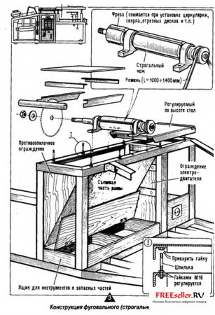
Rice. 3 Design of a planing (jointing) machine
When working on a circular saw, the author noticed a great danger of the saw blade jumping off, especially when the blade hits metal parts. Therefore, in the design of the machine, special attention is paid to lining the window (the groove for the circular disk) with plywood overlays (Fig. 4).

Rice. 4. Design of a saw (circular) table.
Installation of a table on four legs-stands includes telescopic joints of the legs. But we must keep in mind that vibrations during machine operation make screw clamps not reliable enough. Therefore, it was necessary to supplement this device with locking pins.
The possibility of adjustment displacement of the ruler is provided by guides welded to it, made of 016 mm rods.
To facilitate milling, a pressure roller is provided, without which it is difficult to manually feed the workpiece to the cutter.
The drilling and milling device (Fig. 5) provides fastening of the workpieces and their movement relative to the tool. However, when operating the entire assembly, the clamping force of the parts with a common clamp makes it difficult to move them along the transverse slide. Apparently, it is better to mount the workpieces directly on the table. Naturally, when the parts are not processed on the table, the clamp should not be removed. Keep the same thing in mind when equipping the table: the stop used when processing small parts is removed when processing a large part
The machine used a gas tank from a Riga moped. However, the gasoline reserve in it (8 liters) is not enough. It is better to use a larger tank, placing it next to the machine. I would like to draw your attention to the modification of the exhaust pipes from the gasoline engine to the muffler. To distance the hot muffler from the machine parts, I had to make an extension from pieces of 01" pipe using bent adapters.
When preparing pieces of metal profiles, I used a hacksaw: this ensures a clean cut.
After manufacturing, the nodes should be painted. This should not be neglected: paint not only protects against corrosion and gives the machine an elegant look, it also significantly reduces the noise from the machine.
Now about the operating procedure on the machine. First of all, the belt drive is charged to the selected type of drive: from an electric motor or from a gasoline engine. The electric motor is connected in a delta circuit for operation in a single-phase network. Therefore, it is run through capacitors. When starting, the load must be removed. For this stretching device loosen (reduce belt tension) so that the drive pulley in the belt slips. After some unwinding, use a ratchet to tighten the belt. The working shaft gradually unwinds. The gasoline engine is also started with gradual loading.
For selecting quarters (for example, in the manufacture of decorative strips for finishing works) cutters with small height cutting teeth - up to 5 mm. The rotation speed of the cutter is about 3000 rpm. To perform this work, first install an additional ruler on the saw table. The stoppers are removed from the guide posts to protect the table from arbitrary lowering. Then loosen the tightening nuts securing the position of the metal tables relative to the saw table frame. Now these tables can be moved apart to the approximate radius of the cutter (with the cutter and shaft in the uppermost position). Next, loosen the clamping device of the lift rod until the rod can be rotated (tightly). This makes it possible to unscrew the screws that secure the table posts (in this case, the lifting pins of the lift must be placed under the posts). The working surfaces of both metal tables are brought into the same plane, and the table is gradually lowered until the cutter is set to the required height. In this form, fix the lift rod and clamp the wings. This completes the installation of the table. All that remains is to fix the sliding tables in the desired position (the optimal position is found by turning the shaft with cutters).
To select a quarter, you can also install a small-diameter circular saw and, without removing the stoppers or touching the fastening of the metal tables, use a lift to adjust the height of the table so that the saw blade provides the required cutting depth. In this position, the table is fixed with lambs. In this case, the small ruler is not needed and is removed.
The need for a unit for drilling and milling end work arose as a need to mechanize the processing of building parts made of wood. At the end of the shaft we had to make a slot for a Morse taper (for installing drills).
There are two ways to implement the fastening device of the workpiece. The first one is generally accepted. This is the creation of a simple table on which the workpiece is fed onto the tool manually. In this case, you only need to install (adjust) the table height. The second direction is a coordinate device with mechanical feed. It was made by me in the described machine.

I independently designed the woodworking machine presented to the readers, manufactured it with my own hands, and now I successfully use it when building a house on my site. I am convinced how successful the design turned out: compact, technologically advanced, and, I think, quite suitable for its “replication.” The machine is so simple that extremely detailed detailing for its manufacture is unlikely to be required. All fastening points are freely accessible here. So, if desired, the structure can be easily disassembled and, transported in the trunk of a car, assembled in a new place in about thirty minutes.
The proposed version of a universal woodworking machine is with load-bearing elements made of steel angle and sheet steel. Although I know: it will not be difficult for an experienced DIYer to find a suitable replacement for these materials from what is at hand. Of course, with the maximum use of technical solutions that ensure compactness and ease of assembly and disassembly.
Take, for example, welded assemblies and parts. There are not many of them. First of all, this is a base support made of steel angle 50x50 mm. Then there is a frame for installing L-shaped table posts and bearing units of the driven shaft with the working parts of the machine. It is made from steel angle 60×60 mm. Welding work will also be required when rigidly fixing the bushings of the L-shaped racks to the table top, making a limit ruler and a special rotating platform for the electric motor.
The latter deserves special mention. It is welded from pieces of steel angle 40×40 mm and a rod, at the ends of which an M12 internal thread is cut. The rod serves as the rotating axis of the platform, is inserted between the posts and secured on both sides with M12 bolts. The AIR100S4UZ asynchronous three-phase motor with a 100 mm double-groove pulley is installed on the platform using four bolts with Grover nuts and washers.
Tension in the V-belt drive is carried out by twisting the wing on a rod passing through the hole in the platform, followed by locking.
The base support, frame and four 40x40mm angle steel posts, fastened together with M20 bolts, form the frame. Screwed onto it are chutes for sawdust and shavings made of sheet aluminum, as well as other components and parts, including equipment for starting and controlling the electric motor.
The table cover consists of two identical 6-mm steel plates, fastened together by spars using M12 screws with countersunk head and locknuts. As already noted, four bushings are welded to the lower surface of the cover, in which they can rotate L-shaped racks. As for the limiter ruler, it is mounted on the guides using compound clamps and M8 screws.
A few words about the engine. Since the machine uses a three-phase AIR100B4UZ (3 kW, 1410 rpm), to connect it to a single-phase network it was necessary to introduce phase-shifting capacitors - starting and working. And for the most effective use- provide a connection of the windings either in a star or in a delta. The first of these modes (with symbol“Y”) is recommended for sawing and planing with reduced load (when the boards are not too thick). The “Start” button is pressed here if SA1 is disabled, SA2 is enabled, and SAZ is in the “Y” position. In this case, the magnetic starter will work and, by blocking SB1, will ensure a reliable supply of voltage to the motor windings.

1 base support, 2 - stand (steel angle 40×40, 1,800, 4 pcs.), 3 - belt tension rod (steel rod 16, 1,350 with M16 thread at the ends), 4 - rotating engine platform, 5 - electric motor asynchronous three-phase AIR100S4UZ, 6 - double-strand drive pulley (s1 100), 7 - V-belt (2 pcs.), 8 - control panel with “Start” and “Stop” buttons, 9 - table stand (4 pcs.), 10 – M16 adjusting nut with lock nut (4 sets), 11 - Grover washer (4 pcs.), 12 - frame, 13 - double-groove driven pulley (d 50), 14 - table spar (steel angle 50×50, 1,700. 2 pcs. ), 15 - composite table cover (steel sheet 555×500, sb, 2 pcs.), 16 - M12 screw with a countersunk head (22 pcs.), 17 - rotary plane assembly, 18 - circular saw blade, 19 - ruler - limiter, 20 - composite clamp (2 pcs.), 21 - M8 screw (2 pcs). 22 - guide with M16 thread at the end (2 pcs.), 23 - chute for sawdust (aluminum, sheet sZ), 24 - magnetic starter with a switch (Star - Triangle) and two switches, 25 - chute for shavings (aluminum, sheet, s3), 26 - capacitor 100 μ x 400 V (2 pcs.), 27 - motor platform axis, 28 - wing nut M 16.

1 - M8 bolt with Grover washer, 2 - pressure washer, 3 - double-groove driven pulley, 4 - bearing assembly cover (St5, 2 pcs.), 5 - M5 bolt (4 pcs.), 6 - bearing assembly housing (St5, 2 pcs.), 7 - ball bearing 206 (2 pcs.), 8 - plane blade (tool steel, 3 pcs.), 9 - MB spacer bolt (9 pcs.), 10 - clamping bar (StZ, Zpc.), 11 - driven shaft (steel 45), 12 - spacer ring (St3), 13 - profile washer (StZ), 14 - circular saw blade, 15 - tightening washer (StZ), 16 - tightening ring (StZ), 17 - nut M24, 18 - Grover's washer.

The mode with the symbol “D” is operation with increased power. They switch to it after the electric motor, having thoroughly accelerated, reaches the required speed in the “Y” mode. Then feel free to increase the capacity of the phase-shifting capacitor by additionally connecting another 100 µF using SA1. And only then, avoiding strong starting currents, switch the windings to “triangle”, moving the BAZ to position “D”.
Stopping the engine is easy in any of the modes. To do this, just click on the “Stop” button. Then the supply voltage to the coil winding of the magnetic starter will immediately stop, and it will de-energize the electric motor.
As for the SA4 “Reverse” switch, as practice has shown, it does not need to be installed. And the required direction of rotation is achieved in this case during commissioning by “switching the ends” of one of the windings.
And one more note regarding the peculiarities of the functioning of the scheme in question. After stopping the electric motor, both capacitors must be discharged. To do this, you just need... turn on SA1 and SA2.
The time has come to consider the operating features of the machine itself as a whole. It is better to do this by referring to the illustrations.
First of all, adjusting the cutting height, as well as the thickness of chip removal. The required results are achieved here... by turning the nuts. Special, adjusting, with subsequent fixation with a lower nut.
Changing the inclination of the table (when sawing at an angle other than straight) is carried out by simply raising (or lowering) the racks (on the opposite side of the saw blade) to the required height. Optimal shaft rotation speeds (1500 rpm for sawing and approximately 3500 rpm for planing the source material) are achieved by appropriately selecting the diameters of the drive and driven pulleys.
Other machine capabilities? They are directly dependent on which tool is on the working shaft. For example, using various cutters, you can successfully select grooves and quarters. By replacing the saw blade with a cutting wheel, we get a reliable mechanical metal cutter. And with the installation of emery - a machine for sharpening tools.
But all this requires caution. And, of course, the strictest, strict adherence to safety regulations. In particular, when installing the shaft on the bed frame, it must be firmly secured without distortion. By first tightening the bolts on one support, make sure that the other does not rise above the frame and is not excessively pressed against it. Then you need to take the same precaution when tightening the bolts on the second support. Correct the distortion immediately by placing metal spacers under the supports. The bearings must be filled with refractory grease. Make sure that sawdust and shavings do not get into them under any circumstances.
You should treat the plane with no less care. The knives of this working body must be securely bolted. It is worth recalling that when the plane is not in use, it must be covered with a special metal lid (not shown in the figure).
In order to avoid any surprises, the “circular” fastening nuts must certainly be with Grover washers, and it would not hurt to have the other threaded connections properly tightened. Before operating the machine, you should check how well everything is secured. Make sure it's reliable V-belt transmission, turning the shaft itself several times by the drive belt. The latter should rotate easily, without jamming. And only then can you start working.
B. POTAPOV, Ryazan