Progress does not stand still and gadgets touch all areas of life. The ease of use of this or that interior item makes life more comfortable. This also includes the automatic operation of some types of curtains on windows. The designs are no longer new, but for owners who want to install such systems for the first time, it is worth considering the issue comprehensively.
- Control methods
Types of automatic curtains
This roller blinds, indoor roller shutters, Various types blinds. They are classified according to several criteria:
By mounting options
- Directly into the opening are internal roller shutters for the windows. There is a significant drawback - this option does not provide for opening a window or even a vent. Only ventilation mode is possible.
- Overlapping window opening. Maneuverability is becoming wider, but you still won’t be able to fully open the window.
- External options. These are shutters, roller blinds. They are made of metal or plastic. They protect windows from natural precipitation - rain, hail, snow. Significantly prevent the entry of uninvited guests.

By design
- Open. Regular type blinds with open edges. Installed inside the window openings of an apartment or house. The lower edge remains unsecured and has a device for manual control of the blade - a ring, a bracket, a cord.
- Cassette. External roller shutters that, when closed, “move out” from the grooves of the vertical guides. There is an option for mini-cassette curtains - they are installed on auditory or skylights small shape.

It is important to choose the type based on the owners’ goals. External options allow you to install the usual variations of paintings inside - multi-layered, structural, asymmetrical. Nothing will bother them. It is preferable to install internal blinds in new interior styles - minimalism, hi-tech, kitsch. If there is a desire for innovation, act boldly.
Installation of automatic curtains
The model of any version contains a shaft with a built-in electric drive mechanism that winds the blade onto its axis. The opening-closing system operates from a signal from the control panel and moves the canvas to the desired height of the opening. It is then returned to its original state. The design is simple and, if desired, home craftsmen could provide automatic roller blinds with their own hands.

Electric drive design and control
This is the heart of automation. It is a miniature engine with enough power to lift even heavy canvases. Powered by a regular 220V network. Or built-in batteries with Charger. Progressive models are distinguished by built-in functions that improve the comfort of using curtains on window openings. Namely:
- Lifting speed. Automatic curtain rods roll up the fabric from 10 to 25 cm per second. The heavier the fabric, the slower the twist. Actually, such a function is not required in a quiet existence. It is important to ensure instant ascent or descent during emergency situations– fire, burglary, penetration.

- Emergency stop. It is needed to stop the structure mechanism in the event of a fire or an obstacle in the window opening.
- Memory. It will fix the desired position of the canvas for a certain time of day.
- Closer function. That is, automatic roller blinds are adjusted independently if the opening of the window does not suit the owners.
The functions are also available for external roller blinds – metal-plastic shutters. They are controlled from outside or from inside the room.

Automatic roller blinds
Control methods
The designs have several options for action. For example:
- Using remote controls. They can be hand-held, wall-mounted, touch-sensitive, or with buttons. They provide opening and automatic closing of curtains and control of various functions.

- Progressive models integrate a radio receiver, a system powered by infrared emitters. They are installed mainly on windows so that the rays of the sun themselves control the cassette curtain models.
- The remote controls are single- or multi-channel, allowing you to raise automatic curtains on windows in several rooms at once.
- Manual control is associated with photocells - at the slightest natural darkness, automatic roller shutters for windows themselves determine the opening and closing width, respectively.
Functionality and, accordingly, popularity are achieved by remote controls with software, where the above pleasures are taken into account and new ones are added. Naturally, the average price for automatic curtains is 20,000 rubles per device with standard set functions. Anything more comfortable is valued at a decent amount.

Benefits of operation
The fact that it is convenient to open and close curtains is not worth mentioning, although it breeds laziness in the owners. Other advantages of using the following:
- Can be installed on any window size. Wide, high, narrow, small or irregularly shaped openings can be draped well with similar options. Acceptable indoors for various purposes– roller blinds for the kitchen, for example.
- Automatic roller blinds have several opening modes, allowing you not to open all the windows at once, but step by step or one at a time. This gives wide scope for maneuvering sunlight - in different time, the rays will illuminate the rooms as needed.
- Have a remote control remote control and accordingly the timer. Instead of a boring alarm clock, automatic opening of curtains can wake up apartment owners, gently letting in the rays of dawn. Automatic Roman blinds for panoramic windows are especially beautiful - rising slowly and softly, they open beautiful view outside the window, immediately creating a good mood.
- Without constant manual use, the fabric will remain in its original condition - new and sparkling. There is a drawback - it fades, so appropriate reliable options are selected - synthetics in this regard are better than natural fabric.
- In addition to the decorative and utilitarian function, they also have a protective function - automatic fire curtains will prevent oxygen from entering the room in large quantities with the risk of an explosion or backdraft. In case of danger, the built-in alarm will close the windows, thereby protecting the glass.
And, of course, without automatic curtains cannot be done if the window openings are at a height higher than human height or are shutters on the outside of the second floor.

Automatic curtains are a very convenient invention
Disadvantages of automatic curtains
Any design, and especially automatic electric roller shutters, has its drawbacks. It is important to consider them, otherwise the comfort of use will be at risk. For example:
- The remote control is faulty. Since the control is tied to it, you will have to sit in the dark or in an aquarium until the technician arrives, unless the cause is an expired battery.
- Electronic relays for automatic curtains respond to humidity. If the room is somehow connected with a large amount of condensate, then breakdown or even combustion of all circuits cannot be ruled out. It is important to ensure that the motor and electronic components are located in a dry place without access to water or steam.
- Difficult to understand. The desire to have more opportunities plays a cruel joke on us - it’s not easy to understand all the innovations, and the expenditure will be considerable and, it turns out, wasteful. This applies to apartments with elderly family members - it is not easy for them to understand the principle of operation of automatic curtains.
- Expensive repairs or complete replacement equipment - an item that the owner decides on immediately. Many installation companies offer a guarantee for the product and work, but at the same time, it is possible to identify the cause of failure only in the appropriate center. Therefore, the owners will have to pay according to the agreement.
However, even the listed disadvantages of the automatic curtain functioning system do not stop future owners from purchasing it - it really is so convenient.
Where are automatic roller blinds used?

The “habitat” of such models is wide. You should carefully consider all the points to understand whether your apartment or house falls under the described types of rooms. So:
- Traditional design of panoramic windows with curtains with automatic mode. The benefit is significant - decorating large openings from ceiling to floor only with textiles is difficult and not always appropriate if the room is completely glazed. Automation will allow you to make the lighting inside as needed. It is important that such rooms are decorated with roller blinds in a single color scheme and dimensions.
- Progressive electric curtains for bedroom, nursery and even kitchen windows. It’s nice to wake up with such paintings. The living room is no exception - bold styles require a progressive solution, which, however, does not exclude the use of traditional curtains. It is important to note that in this case it is better to use automatic Roman blinds - they are cozy and homey.
- Attic rooms. It is difficult to arrange standard woven curtains there. You have to use special inclined holders so that the canvases do not sag perpendicular to the floor. Using the automatic version of roller blinds for plastic windows, problems will not arise. Everything is fixed on the wall, and operation becomes comfortable.
- Soundproofing curtains will be required for the windows of domestic premises. In the laundry room or home boiler room. The units sometimes make completely unbearable sounds. At the same time, it is important to leave the installation of such options to professionals and adjust the possibility of installation with permissive safety rules. Some cabins, for example, with a gas boiler require open windows, so automatic roller shutters are equipped with a preset program and alarm.
WATCH VIDEO INSTRUCTIONS
So, the ease of use has been determined, and there is a desire to install progressive gadgets in the form of automatic curtains. Now it is important to determine the installer company - there are many of them and some have already proven themselves to be responsible and reliable performers of the work. It is worth focusing on real reviews owners similar designs– they tell a lot about the company and the nuances of using the products.
Now you know what automatic curtain rods and automatic window blinds are.
In this article I will talk about the design of an automatic curtain drive installed on my balcony. There we grow flowers that are harmed by direct sunlight. In addition, in the summer, if the balcony windows are closed, in direct sunlight the air on the balcony quickly overheats. However, when there is no direct light, it is advisable to open the curtains - the shadow also does not contribute to the growth of flowers. Therefore, to maintain acceptable illumination on the balcony, I automated the operation of the curtains.
Mechanics
The curtains were originally already on the balcony. There are two of them, both suspended on a metal cable stretched under the ceiling from one wall of the balcony to the other. It is clear that you need to move both curtains at once, and due to the friction of the curtains on the cable (it is quite rough), the required force must be quite large. In addition, sometimes there may be obstacles in the path of the curtains, for example, a slightly open balcony window, which further increases the strength requirements.
Thus, the drive must be sufficiently powerful and reliable - on the balcony it often happens high humidity, quite a large temperature difference between winter and summer is possible. Therefore, I based the drive on a car window lift drive. It has sufficient power and is capable of producing high torque (it has a built-in worm gear) and very reliable.
The mechanical diagram of the drive is shown below:
More details about the design. A plastic roller with a groove is attached to the window lift drive shaft (on the left in the diagram), on which a turn of rope is wound. The drive is mounted on one of the walls of the balcony. A similar roller is attached to the opposite wall, through which a rope is also thrown.
After this, the rope is tensioned so that the friction of the rope on the drive roller is enough to move the curtains. The opposite ends of each curtain are attached to a rope so that when the motor rotates, the curtain moves or moves apart.
To test the operation of the drive, I made a smaller model of it. The window lift drive and the independent roller were mounted on a board, a rope was pulled between them, after which it was possible to check the operation of the electronics and measure the force developed by the drive.
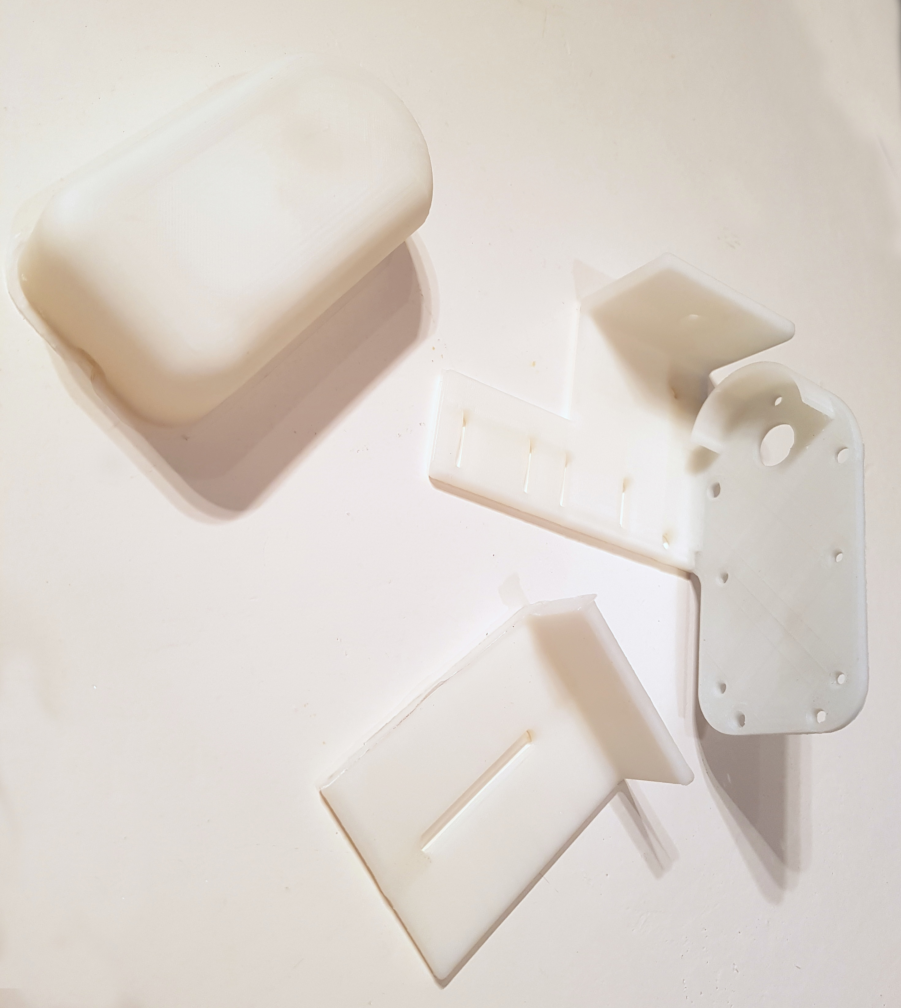
Photo of the drive itself on the layout:
As can be seen from the photo, a fairly large thin plate is attached to the window lift drive (I used textolite). Attached to it metal corner with two holes through which a rope is passed. This is necessary so that the turn of the rope on the roller does not get tangled, for this purpose the holes in the corner are made on different heights relative to the plate.
To the right of the corner are limit switches needed to stop the curtains in their extreme positions. In order to indicate these positions, two plastic straws(only one of them is visible in the photo next to the bottom switch). The tubes are arranged so that when the curtain reaches its extreme position, one of them presses the switch, and for reliable pressing, a metal plate is attached next to each of the switches, which presses the tube to the switch.
Three metal racks attached to the plate are needed to secure the drive cover.
Both rope rollers are made from furniture wheels. Using a drill and a file, you need to make a groove in each of them; two turns of rope should fit in the groove of the drive roller. The drive roller is attached to the shaft by tension, and the hole in it had to be bored out to a square one, since the drive shaft is square.
The drive is attached to the wall of the balcony using suitable furniture corners (one of them is visible in the photo on the left). There are enough mounting holes in the window lift drive, so there are no problems with fastening.
View of the drive already attached to the wall and covered with a lid:
In order to tension the rope, a special screw with a nut is used, to which the ends of the rope are attached:
The end of one of the curtains is also attached to it.
Electronics
All my electronics are divided into two parts - power and control. The main task of the power section is to provide power to the drive motor. The power window drive can draw very high current. To reduce this current, I reduced the drive supply voltage to 5 volts, but even so, the maximum current consumed by the motor can reach up to 3A. To provide such a current, I used a printer power supply capable of delivering a voltage of about 30V and a current of up to 0.7A, as well as a DC-DC converter of up to 5V. By lowering the voltage, DC-DC is quite capable of delivering the required current.
Motor power control is carried out using a powerful relay designed to change the polarity of the signal, and a MOSFET that controls the voltage supply to the motor. Thanks to the use of MOSFETs, it is possible to control the rotation speed of the motor, but this feature is not currently used.
Also installed on the power section are stabilizers designed to power the control electronics and the engine power control circuit. The stabilizers are powered from a lower voltage circuit of the power supply, the voltage there does not exceed 12V.
The control electronics are represented by the STM8S microcontroller. The controller performs quite a lot of functions - measuring illumination, making a decision about starting the drive, monitoring the position of the curtains using limit switches, controlling the power supply of the drive, controlling the drive in manual mode - according to commands from the remote control. In addition, a radio module based on NRF24L01 and a 1-Wire bus are connected to the controller, through which three temperature sensors are connected. Using the radio module, you can control the drive and read temperature values at different points on the balcony and on the street, however, at the moment the second radio module is connected only to the breadboard, so I will not consider this functionality further.
The printer power supply used has an input for switching it to Stand-by state. I also use it, which reduces the energy consumption of the structure. The program takes into account that the power supply switches to operating mode with a certain delay, and after 30 seconds of inactivity of the drive, the power supply again switches to Stand-by mode.
Indication of drive operation using a three-color LED (only blue and red diodes are used). Blue lights up when voltage is applied to the motor, red starts flashing periodically if there are errors in the drive operation. The number of flashes allows you to determine the error number.
For audible signaling of some events (for example, when a command is given to close curtains that are already closed), the drive motor itself is used. A PWM signal with a small duty cycle is supplied to it, as a result of which the engine beeps quite loudly.
A photoresistor attached to the window with a suction cup is used as a light sensor. Since the suction cup may fall off the window, there is a small button next to the photoresistor. While the suction cup is held on the window, the button is pressed against the window. If the suction cup falls off, automatic operation drive stops and the red diode starts flashing. If the sensor is not connected to the connector, this is also detected by the controller.
Type of light sensor:
Since the illumination of the sensor can change sharply - due to various flashes on the street, partly cloudy weather - the data from the sensor has to be filtered. I have implemented the following processing algorithm: data from the sensor is digitized at a frequency of 10 Hz and written to an array. Once a second, the value of this array is averaged (primarily this is needed to filter out noise and flashes). Next, the resulting values are added to another array of 600 elements; after reaching the end of the array, recording begins from the beginning. Also, this array is analyzed every second - the controller calculates what percentage of the array elements is less than a certain threshold (with increasing illumination, the voltage at the output of the photosensor drops). If the values of more than 66% of the elements are less than a given threshold, then it is considered that the illumination is high enough and the curtains can be closed. In this way, periodic changes in illumination are filtered. At the same time, a limitation is also imposed on the operating frequency of the drive - in automatic mode, the motor turns on no more than once every ten minutes.
As I mentioned above, it is possible to control the curtains from the remote control. Using the remote control, you can fully open and close the curtains, partially open them, and start the drive based on the instantaneous illumination value. When controlled from the remote control, there are no restrictions on the operating frequency of the drive.
It is also possible to programmatically reboot the controller.
When moving the curtains, the controller monitors the state of the limit switches. If, after starting to move, the corresponding switch does not operate within 20 seconds, the engine stops working. To continue operation of the drive after eliminating the malfunction, you just need to reboot the controller.
All electronics are installed in a standard plastic housing:
One of the switches is needed to switch the electronics to automatic operation mode, the second allows you to completely turn off the power to the motor.
Using 3.5mm Jack sockets, a light sensor, TSOP for receiving data from the remote control, and external temperature sensors are connected to the device.
The LED is covered with a white cap so it can be seen from any angle.
View of the assembled and installed electronics unit:
Video of the drive operation (control from the remote control):
One day, after a hard day at work, I came home and realized that I wanted to relax, and not walk around and close the curtains. I would like to see them closed in the evening and open in the morning, without dancing in front of the window. Googling different solutions, it was decided to do everything myself.
By popular demand, I am posting all my work on converting regular roller blinds into automated ones with remote control. Be careful, there are a lot of photos!
First, about roller blinds:
- Pros: roller blinds visually expand the space, are beautiful and inexpensive. Very easy installation. Each window can be controlled separately. Frees up space on the windowsill.
- Difficulties: manually opening 5 windows already takes a long time. The mechanism itself prevents the corner window from opening completely (example: the mechanism at the top balcony door rests against the wall and does not allow the passage to open completely). Because of this, it is necessary to hang curtains from the outside of the window. The price of even Chinese motorized curtains starts at 2,000 rubles, multiply by 5 and immediately think about how to do everything with improvised means.

A little about the tasks:
Needs to be added to regular roller blinds from a hardware store remote control and connect to a smart home on the openSource platform Home Assistant. And you still need to maintain the usual control of the string.

Choice of motors:
If everything is automated, then speed does not matter, so motors with gearboxes can be used. Brushed motors are cheap, but not the most reliable thing for daily use. Servos also have commutator motors and are not stable during constant rotation. Stepper motors look like an excellent option. They are silent, you can control the position, they cost pennies. As a result, a set of 5 28BYJ-48 engines with a ULN2003 driver cost me $10

About the 28BYJ-48 engine:
There were questions about the power of this engine. Fears that he would be weak were not justified. Or rather, if you use a full-step mode, then the motor is very frail, if you use a half-step mode, then you can’t stop the shaft with your bare hands. For those who don’t have enough power, there are many articles on the Internet on how to raise the voltage, turn it into bipolar and other improvements.
About sensors:
Since we still have manual control, and we don’t want to waste the engine, we need curtain position sensors. At a minimum, one sensor is required at one end, but two are better. You can use any end switch, optical one, etc., but I personally chose the reed switch because... gluing a neodymium magnet on the other side is very simple and should work stably and durable. I chose the reed switches themselves for aesthetics already in the housing. Plus, it provided for setting the distance from the shaft. The height can be adjusted with spacers.

About the mounting design:
The task was to design the case as simple as possible for manufacturing on a 3D printer with minimal modifications. Modeled in Fusion 360. The complete mount clings to the top of the window, but such a design on an FDM printer would be difficult to make with the required strength requirements, so a design with one screw for adjustment was invented.

In total, we got three parts for 3D printing. Link to download 3D models.
Main part for the motor, control board on ULM2003, mounting of reed switches, motors, line for stabilizing curtains, and adjusting screw.
A lid to cover all this mess. A clamp or in other words a hook.
The design of the curtains itself contains several springs, which work as a brake if you pull the curtains (the spring is tightened) or release it if you twist the rope.


When assembling, you need to make one modification: use wire cutters to break the rim that covers the rope, because... Now we have our own fixed rim that prevents the rope from falling out.

Control:
The stepper motor will be controlled by a NodeMCU on an ESP8266. It was chosen because it is cheap, has a backup Wi-Fi channel, and is quite easy to write the necessary scripts on. If you need more than two curtains or additional sensors, then the microcontroller legs are no longer enough, you can look towards the ESP32. (esp32 is not shown in the photo, because it is in the junction box)

Software part:
The development environment can be any. ESP32 can be programmed via Arduino IDE. But I chose Visual Studio Code for myself because of its speed, modularity and freeness. In this environment, you can develop for almost any platform (not just hardware). You can even connect IAR ARM. (But that's a completely different topic)
The program's task is simple:
Connect via Wi-fi
Connect to MQTT broker
Subscribe to topic
Control the speed of two motors
Monitor the condition of the limit sensors
Send current steps to the broker
Sources can be taken
In this article I will talk about the design of an automatic curtain drive installed on my balcony. There we grow flowers that are harmed by direct sunlight. In addition, in the summer, if the balcony windows are closed, in direct sunlight the air on the balcony quickly overheats. However, when there is no direct light, it is advisable to open the curtains - the shadow also does not contribute to the growth of flowers. Therefore, to maintain acceptable illumination on the balcony, I automated the operation of the curtains.
Mechanics
The curtains were originally already on the balcony. There are two of them, both suspended on a metal cable stretched under the ceiling from one wall of the balcony to the other. It is clear that you need to move both curtains at once, and due to the friction of the curtains on the cable (it is quite rough), the required force must be quite large. In addition, sometimes there may be obstacles in the path of the curtains, for example, a slightly open balcony window, which further increases the strength requirements.
Thus, the drive must be quite powerful and reliable - there is often high humidity on the balcony, and a fairly large temperature difference is possible in winter and summer. Therefore, I based the drive on a car window lift drive. It has sufficient power, is capable of producing high torque (it has a built-in worm gear) and is very reliable.
The mechanical diagram of the drive is shown below:
More details about the design. A plastic roller with a groove is attached to the window lift drive shaft (on the left in the diagram), on which a turn of rope is wound. The drive is mounted on one of the walls of the balcony. A similar roller is attached to the opposite wall, through which a rope is also thrown.
After this, the rope is tensioned so that the friction of the rope on the drive roller is enough to move the curtains. The opposite ends of each curtain are attached to a rope so that when the motor rotates, the curtain moves or moves apart.
To test the operation of the drive, I made a smaller model of it. The window lift drive and the independent roller were mounted on a board, a rope was pulled between them, after which it was possible to check the operation of the electronics and measure the force developed by the drive.
Photo of the drive itself on the layout:
As can be seen from the photo, a fairly large thin plate is attached to the window lift drive (I used textolite). A metal corner with two holes is attached to it, through which a rope is passed. It is needed so that the turn of the rope on the roller does not get tangled; for this purpose, the holes in the corner are made at different heights relative to the plate.
To the right of the corner are limit switches needed to stop the curtains in their extreme positions. In order to indicate these positions, two plastic tubes are put on the rope (only one of them is visible in the photo next to the bottom switch). The tubes are arranged so that when the curtain reaches its extreme position, one of them presses the switch, and for reliable pressing, a metal plate is attached next to each of the switches, which presses the tube to the switch.
Three metal posts attached to the plate are needed to secure the drive cover.
Both rope rollers are made from furniture wheels. Using a drill and a file, you need to make a groove in each of them; two turns of rope should fit in the groove of the drive roller. The drive roller is attached to the shaft by tension, and the hole in it had to be bored out to a square one, since the drive shaft is square.
The drive is attached to the wall of the balcony using suitable furniture corners (one of them is visible in the photo on the left). There are enough mounting holes in the window lift drive, so there are no problems with fastening.
View of the drive already attached to the wall and covered with a lid:
In order to tension the rope, a special screw with a nut is used, to which the ends of the rope are attached:
The end of one of the curtains is also attached to it.
Electronics
All my electronics are divided into two parts - power and control. The main task of the power section is to provide power to the drive motor. The power window drive can draw very high current. To reduce this current, I reduced the drive supply voltage to 5 volts, but even so, the maximum current consumed by the motor can reach up to 3A. To provide such a current, I used a printer power supply capable of delivering a voltage of about 30V and a current of up to 0.7A, as well as a DC-DC converter of up to 5V. By lowering the voltage, DC-DC is quite capable of delivering the required current.
Motor power control is carried out using a powerful relay designed to change the polarity of the signal, and a MOSFET that controls the voltage supply to the motor. Thanks to the use of MOSFETs, it is possible to control the rotation speed of the motor, but this feature is not currently used.
Also installed on the power section are stabilizers designed to power the control electronics and the engine power control circuit. The stabilizers are powered from a lower voltage circuit of the power supply, the voltage there does not exceed 12V.
Power circuit diagram
The control electronics are represented by the STM8S microcontroller. The controller performs quite a lot of functions - measuring illumination, making a decision about starting the drive, monitoring the position of the curtains using limit switches, controlling the power supply of the drive, controlling the drive in manual mode - according to commands from the remote control. In addition, a radio module based on NRF24L01 and a 1-Wire bus are connected to the controller, through which three temperature sensors are connected. Using the radio module, you can control the drive and read temperature values at different points on the balcony and on the street, however, at the moment the second radio module is connected only to the breadboard, so I will not consider this functionality further.
The printer power supply used has an input for switching it to Stand-by state. I also use it, which reduces the energy consumption of the structure. The program takes into account that the power supply switches to operating mode with a certain delay, and after 30 seconds of inactivity of the drive, the power supply again switches to Stand-by mode.
Indication of drive operation using a three-color LED (only blue and red diodes are used). Blue lights up when voltage is applied to the motor, red starts flashing periodically if there are errors in the drive operation. The number of flashes allows you to determine the error number.
For audible signaling of some events (for example, when a command is given to close curtains that are already closed), the drive motor itself is used. A PWM signal with a small duty cycle is supplied to it, as a result of which the engine beeps quite loudly.
Control circuit diagram
A photoresistor attached to the window with a suction cup is used as a light sensor. Since the suction cup may fall off the window, there is a small button next to the photoresistor. While the suction cup is held on the window, the button is pressed against the window. If the suction cup falls off, the automatic operation of the drive stops and the red diode begins to flash. If the sensor is not connected to the connector, this is also detected by the controller.
Type of light sensor:
Since the illumination of the sensor can change sharply - due to various flashes on the street, partly cloudy weather - the data from the sensor has to be filtered. I have implemented the following processing algorithm: data from the sensor is digitized at a frequency of 10 Hz and written to an array. Once a second, the value of this array is averaged (primarily this is needed to filter out noise and flashes). Next, the resulting values are added to another array of 600 elements; after reaching the end of the array, recording begins from the beginning. Also, this array is analyzed every second - the controller calculates what percentage of the array elements is less than a certain threshold (with increasing illumination, the voltage at the output of the photosensor drops). If the values of more than 66% of the elements are less than a given threshold, then it is considered that the illumination is high enough and the curtains can be closed. In this way, periodic changes in illumination are filtered. At the same time, a limitation is also imposed on the operating frequency of the drive - in automatic mode, the motor turns on no more than once every ten minutes.
As I mentioned above, it is possible to control the curtains from the remote control. Using the remote control, you can fully open and close the curtains, partially open them, and start the drive based on the instantaneous illumination value. When controlled from the remote control, there are no restrictions on the operating frequency of the drive.
It is also possible to programmatically reboot the controller.
When moving the curtains, the controller monitors the state of the limit switches. If, after starting to move, the corresponding switch does not operate within 20 seconds, the engine stops working. To continue operation of the drive after eliminating the malfunction, you just need to reboot the controller.
All electronics are installed in a standard plastic housing:
One of the switches is needed to switch the electronics to automatic operation mode, the second allows you to completely turn off the power to the motor.
Using 3.5mm Jack sockets, a light sensor, TSOP for receiving data from the remote control, and external temperature sensors are connected to the device.
The LED is covered with a white cap so it can be seen from any angle.
View of the assembled and installed electronics unit:
Video of the drive operation (control from the remote control):
The idea was born a long time ago and took a long time to mature. It all started with moving to another apartment, the windows of which face east. In winter it’s still okay, but in summer the brazen sun rises when I’ve just fallen asleep or haven’t even gone to bed yet. It shines brightly right into my eyes, telling me not to sleep through the summer. Of course, you’re right, it’s not a good idea to sleep in the summer, but somehow it’s still not possible to not sleep at all. Curtains have been invented to protect against the sun a long time ago, and I even have them. Quite dense. But not enough. A bright light penetrates them through, not direct rays, but still bright. And most importantly, you must remember to close them in the evening and open them during the day when you wake up. Someone does it at home smart House, someone is crazy. Well, my house is lazy, it’s all about me. The owner should not bother himself with such hard work as moving the curtains twice a day. Let the curtains open smoothly some time before the alarm clock (or even instead of it). The sun should wake up my majesty, but not prevent him from sleeping, right?
Spoiler: 
I started thinking about how to automate this matter. The first thought is obvious, a cable, a motor and hang it all on the curtains. While I was thinking about how to implement it, fix it, how to attach end sensors, this and that, while I was trying to overcome laziness and do it, only three years passed. But he never did. And this is good. Because by that time another thought had dawned on me. Instead of moving curtains that don't move easily and don't block light enough, it's better to use blinds. Well, when I started googling about them, I found out about such a cool thing as roller blinds. Somehow I have never encountered them before.

Roller blinds are a cross between blinds and curtains. A piece of fabric that is rolled up at the top when not needed. They are hung on each window separately. On opening ones - directly on the sash, you can open the curtains in any position. Of course there are different colors, patterns and light transmittance. And, just what I need, there are “blackout” options, that is, they block the light almost completely. IN the usual version controlled by a hanging loop of rope-chain. The width varies, but if necessary, you can cut it to fit. Prices also vary, somewhere from 600 rubles (~$10). Here, for example, in . If you need simple, no frills, then it’s quite acceptable, it seems to me. 
I bought it, hung it - great! All that remains is to automate. There are no problems with the motor, the curtain is quite light, nothing powerful is needed. I decided to remove the manual cord control. Without it, the motor shaft can be rigidly connected to the bobbin. This simplifies the design. The case, with a 3D printer, turns from a problem into a design issue. But electronics... There are many options for solving the problem. Detailed analysis I’ll hide why I chose this one under the spoiler.
Options, thoughts, compromises
First, we need to decide whether we want to control the curtains from a button, remote control, smartphone, etc. Or either way at once. And directly or integrate into any lazy home. If you integrate, then how to connect, wires, Wi-Fi, bluetooth, radio channel or some other perversion. Everyone has their own preferences here. I chose Wi-Fi as a fairly versatile option. Creating wires is unnecessary. IR/radio remote controls make no sense, it’s better to have one ring to control them all, oh, that is, one smartphone for all home automation. Moreover, if desired, redirecting commands from anywhere to Wi-Fi is quite simple. I have an IR receiver in my computer, I turn off the lights and control the music with the TV remote. It will be necessary (and if I find another unoccupied button) - it will also control the curtains.
Well, since Wi-Fi, then of course ESP8266. Modules built on this microcontroller are inexpensive and are quite suitable for the task. I know about ESP32 (almost the same thing, but newer and also with bluetooth), but I haven’t used it yet.
And here a compromise is brewing that will have to be made. Carry the power supply with wires. Because if you turn the motor a couple of times a day, a battery, for example 18650, will last a long time. But feeding the ESP8266 continuously is not possible.
According to quick estimates, the engine consumes around 220 mA, we take an 18650 battery for 2500 mAh, we get 5 volts from it with a boost, 2500 * 3.6/5 * 80% = 1440 mAh, which means you can spin it for 1440/220 = ~ 6.5 hours. It takes about 2 minutes to raise or close (depending on the window height and speed). About 90-100 round trip cycles on one charge. 3 months would be enough. And if you use 2 batteries, and with increased capacity - more than six months. Acceptable. But in addition to the engine, there are electronics.
The ESP8266 has several power saving modes for such cases. But if we want (and we do want) that a command to open and close the curtains can be sent at any time, then Wi-Fi cannot be turned off, and without this we won’t be able to save much. My experiments came to nothing, at least. The average consumption remained somewhere around 5-10mA, which is clearly a lot for an autonomous power supply. Worse yet, my esp "shock periodically stopped saving energy, as soon as I pinged it 10 times. I don’t know what kind of glitch it was, I didn’t bother to figure it out. Well, even if I’m cranky, I can really squeeze out 2-3 mA, it’s still not an option. Changing batteries once a month ( and this is still in good case) - too much. Turning on Wi-Fi occasionally just to synchronize the schedule is not an option. You never know when you need to close the curtains, suddenly you want to watch a movie during the day, but the bright light of the sun gets in the way. So we pull the power with a wire. The power supply is low-voltage, the currents are small, it is easy to install between the frame and the sash, behind the window skirting board, from the side of the balcony, or in some other way to disguise it. But you did it once and forgot, and you don’t have to change the batteries every time. You can switch to batteries if only scheduled work + manual control by a wired button is enough. I'll think about this option for the dacha. Or change Wi-Fi to BT, RF, IR or something else with two letters that doesn’t cost much. By the way, a quick Google says that there are also battery drives with remote control, who needs. And I will farm as I please. With wires. It's possible to hide them. 
Another question arises, here we have 2-3 nearby (well, I specifically have 2) windows (I mean separate glasses. Fixed, opening or a balcony door, in one window opening) in a room, you need the same number of curtains, motors too, but how many “brains”? In general, of course, the ESP’s computing power is more than enough; we’re not planning rocket science here. But, on the other hand, then, in addition to power supply, you will need to lay wires to control the motors, for stepper motors this is 4 pins, if directly. The most common and cheap Chinese ESP headsets also have a limited number of pins. And if you stuff these scarves directly into the motors, one for each, then everything becomes simpler. So I decided that if a gun and shells cost a penny, then I could shoot sparrows with it. A simple, modular, easily repaired, compact solution outweighs the savings on matches. If the electronics of one drive breaks down, the second one will allow me to open the window and I won’t die from lack of lighting (yes, I’m still a vegetable).
Usually, when making lazy automation, you definitely need to think about backup control options, since it will definitely break down someday. And if it doesn’t break, the lights will be turned off. Or Wi-Fi will hang. I refused mechanical manual control; the chain at the window does not dangle. This means that if there are problems with power supply, we will not be able to do anything about the curtains. Okay, we'll survive somehow. You can power it from an uninterruptible power supply or make a 5 volt uninterruptible power supply. It’s another matter if everything works, but Wi-Fi has dropped. There is a free pin on the board where you can attach a button to manually launch the curtain. The drive is high, the button can be pulled down to hang on a cord. But I didn't do that. My router is powered by UPS, does not glitch, has uptime for a year or more, and only reboots when updating the firmware and replacing batteries. And in case of a fire in the house, as happened recently. The driveway was on fire cable channel, there was no light for a couple of hours, the uninterruptible power supply quickly gave up. But this is rare. In general, for some people the button may be convenient as another control channel.
Now let's move on to the details, in every sense.
 Engine. Here the choice was obvious to me. Widespread . The price is 1.5-3 bucks, depending on the quantity, driver board configuration and the greed of the seller. Sold on every corner of the Chinese Internet. There are 5 and 12 volts, I used the most common, five-volt. Represents stepper motor(i.e. it can be rotated in small “steps” to the desired angle or the desired number of revolutions) combined with a gearbox. Due to this, with a very modest weight (~30 g) and dimensions (~3x3x2 cm), it develops quite good power, about 300 grams of force per centimeter. This is not much, but it is enough to wind the curtains. The gearbox also provides effective shaft braking in the absence of power. You can turn it by hand, but with a decent amount of effort, more than a worker. So the curtain will not unwind spontaneously when the power is turned off. And another plus is that it is very quiet. It is almost inaudible already a meter from the ear. When attached to a hard surface, vibrations during operation slightly increase the noise; it becomes slightly audible in a quiet room, but it is unlikely to wake anyone up. Me for sure. In general, as I understand it, they are often used to control the curtains of air conditioners. And she can move all night in swing mode (I don’t know how it is in Russian, in short, when she waves back and forth). The gearbox is plastic, but I don’t consider it a disadvantage, the load is small, wear is unlikely to affect the “curtain” mileage, but somehow it lives in a conduit? Someone actually made mini 3D printers using these mini 3D printers, and there was non-stop movement. The main thing is not to twist it by the shaft too often, this can easily kill it. It also has quite significant shaft play, both axial and radial. Quite significant. But again, in this application It doesn't matter or matter at all. So, I think it has only one minus, again a consequence of the gearbox, the motor is slow. 15-25 RPM, i.e. one revolution in 3-4 seconds. Slower is possible, faster is not. But curtains are like that, no rush is required, on the contrary, you need to raise them slowly and majestically. So it fits.
  The motor can turn the curtains at a specified number of revolutions. But this is all relative, in Einsteinian terms. And we need, in Archimedean style, a fulcrum from which to count. If you have two such control points, above and below, then you can generally use a regular engine and turn it “all the way”. But it’s inconvenient to do this from below, but you can put a microphone on top. (I saw on the Internet an implementation without limit switches at all, the curtain was trained the first time it was turned on. But this is not my way, the position may be reset when the power is turned off, if you do not save it to flash memory every time, forcing it. The motor may, for some reason, skip steps. You never know.) The microswitch will be pressed by the fully raised curtain, and down we will unwind to the length specified during setup. In fact, it would probably be even better to use a reed switch and magnet at the bottom of the curtain. But I didn't think of that before. A comrade told me when they discussed this topic in smart curtains from Xiaomi. I left the mics, but nothing prevents you from using reed switches if desired. Mikriks cost a little over a buck per bunch. Search for micro limit switch, for example. You need the smallest ones, 13x6mm, preferably without a roller. Although the video can always be cut.
Mechanically, all that remains is the body and a couple of M3 screws to put it together. We'll draw the body and print it live. The body should ideally be made as compact as possible, for aesthetic reasons. And why waste extra plastic? This means we make the board first, then the body is already built on it.
Electronics.
 That means with our hearts... although no, with our brains, we will have an ESP8266. This microcontroller requires external memory, an antenna, and other small things that are difficult to solder at home. So we take a ready-made scarf. A lot of them different options, from very small to almost Arduino-like. My choice is ESP-07. One of the most compact options, with ceramic antenna. There is even a connector for an external antenna, but it is not needed within the apartment. The ESP-12 is a little larger due to the antenna “drawn” on the board. The price is 2 bucks, plus or minus as you negotiate.
  These brains cannot directly control the engine. They'll tear themselves up. I don’t remember exactly how much pin current is allowed on the ESP, it seems 12 mA, but it needs to be around 200-300. Transistors are needed for amplification. The easiest way is to take a chip with keys, ULN2003. It also contains all the diodes necessary to control an inductive load. Often boards with this microcircuit are sold complete with a motor. Only there it is in a DIP package, which is unnecessarily bulky. It’s good to have such scarves for prototyping with wires, and in ready product install ULN2003ADR in SO-16 housing. Even in retail Chip and Deep it costs only 19 rubles; on Ali it’s generally less than a dollar for a dozen.
 The engine requires 5 volts, the brain needs 3.3. So we install a stabilizer chip. There is a huge choice here. I took the most popular one - AMS1117-3.3 in the SOT-223 package. The price is a dollar for a dozen, for $3 they will send a hundred at once. They are not suitable for powering ESPs from lithium, the voltage drop is about 1 volt, but powering them from 5V is just right. I use them often, for esp and STM32.
You also need 0805 resistors with a nominal value of 10KOhm, plus or minus. Three capacitors, also 0805, nominal 1 µF or more. Less is not advisable, it can be buggy. And pins for connecting everything so as not to solder tightly. The most common, single-row straight lines, pitch 2.54. Color to taste. 
 Powered by 5 volt source. Current consumption is up to 0.4A per curtain. An honest 1 amp unit should be enough for two curtains. If you don’t raise them at the same time, then even 0.5A will probably be enough. But it's better not to take risks. If possible, it is better to overclock the power supply by 6 volts; this will compensate for the drop in the wires and keys of the motor driver. Especially for wide, heavy curtains.
 For the initial firmware you will also need a USB-TTL adapter. Any. You can use any Arduino with a USB port as it. The adapter costs a penny, but you can ask someone for a while; further firmware updates, if necessary, can be done over the air.
Pay.
The circuit is simple, the connection is standard. I drew and then routed the board in DipTrace.
It turned out to be a little more difficult to install the board. I wanted to make it as compact as possible, but without giving up 0805 small things, as the most common and quite comfortable for soldering. And the tracks are 0.4mm, quite acceptable for making with LUT. The board is double-sided. It was possible to reduce the length by another millimeter or even two by removing the optional resistor R5 between DTR and GPIO0, but I thought about it a little late.
The boards can also be ordered in China. JLCPCB seems to still have a promotion with free shipping on your first order. Then 2 usd per ten (or even much more if you then file it by hand). With delivery it’s already worse, it’s over ten. But you can look for options, there are many of them. I have never ordered one myself; I make do with photoresist. 
Frame.
During the process, the body went through a long evolutionary path, starting with a simple bracket for the engine.
For some time I puzzled over how to secure the microphone and how to press it. I tried options for attaching a fork to it, between the teeth of which I passed the curtain, so that the weight at the bottom of the curtain pressed this fork when lifting. All this was unaesthetic and impractical. But a beautiful solution was eventually found. You just need to pull out the plastic weight bar a little so that it rests against the drive housing. Make the bottom wall of the case flexible and hide the microphone inside. 
The extended tip of the bar can be closed with a vertical U-shaped profile, glued to the window frame. Then the curtain will adhere to the glass even on tilting windows. For symmetry, the plank is cut in half and pulled out on both sides. 
The housing is designed to be attached to the base that comes with the curtains. There is quite a wide choice of mounting methods: on the window by the edge, with tape, with screws. It's stupid to refuse. For other curtains, the size of the fastening bar may differ; the model will have to be adjusted. But it’s not difficult, I drew in OpenSCAD, well, as I drew, everything is specified there in text. So it shouldn’t be difficult to fix, just change a few numbers. But right away it may be difficult to understand my shitty code. If anyone needs it, I’ll tell you where and how. 
We print. I prepare the task for the printer in Slic3r. I try to adjust it so that it prints only in perimeters, without filling. I set the number of upper and lower layers so that the lower (when printing) wall is completely filled. 
My settings are like this. Printing in a layer of 0.25 mm, the first layer is 0.3 mm, 3 perimeters (for the lid it is better to put more perimeters, 5-6), continuous layers: 4 upper, 4 lower. I printed with ABS (a little difficult to print, it’s better to print with a full-height protective perimeter) and PLA. But I settled on PETG, it’s easiest for them. It takes 17 grams to print the body, about 6 for the cover. Printing time is 45- 50 minutes and 15 minutes, respectively.
After printing, you can treat it with sandpaper and solvent to obtain a glossy surface, but I’m lazy, so I decided that [s]it will come off and not be visible from afar. 
We are also printing an adapter for the axle. It also needs to be adjusted to a specific curtain if it has a different mounting diameter. Mine have 15-16 mm. 
We solder.
I usually make boards with photoresist. For me it comes out a little longer than LUT, but a little better in quality and less defective.
The bad thing about making boards at home is that you will have to solder jumpers into the vias. On factory boards, the holes inside are covered with metal and this ensures contact between the sides of the board. Well, I make jumpers from a core of stranded wire. I put the board on the anvil, insert the core, bite it a millimeter above the board and hit it with a hammer. It is better to slightly lift the board before hitting it so that it unravels evenly from above and below. It turns out to be quite reliable, and if you then also tin it, it’s generally excellent. And nothing sticks out; you can make transitions right under the microcircuits. 
Solder the parts. Pay attention if you suddenly repeat it. Resistor R5 is 300 Ohm (designation 301), and not 10K (103) like the others. Don't get confused. It is generally optional; you can solder the jumper. Just in case, so as not to burn the DTR line when experimenting with the firmware. WITH reverse side There is also an optional resistor R7 (pictured above), do not solder anything there at all, this is for experiments with deep sleep only. 
Some pins also serve as interlayer jumpers. So you need to solder them on both sides. First, we solder it from the bottom, then we lift the plastic skirt and carefully, using not too much solder, solder it from the top. Ideally, the skirt fits almost in place; there is a small indentation in it. I solder so-so, don’t pay attention. I'm generally a jack of all trades. 

Initial firmware.
If you already have the Arduino IDE installed, then the easiest way to flash it is from it. If you have not yet installed a package to support ESP8266, then you need to add it (Tools - Board - Boards manager, esp8266 by ESP8266 Community - Install, version 2.4.1, at the moment. In 2.3.0 I had glitches and slowdowns). Next we set the parameters. 
To avoid installing the Arduino IDE, you can use a free utility from Espressif, the developer of this chip. Download and launch. In the settings we set everything as in the screenshot, in the first line we just select our path to the downloaded bin firmware. In the address “0x0000” it’s an x, not a ha, if that’s the case. And, it is important, we choose the right memory size. For ESP07 it is usually 8 Mbit (=1 MB). For other boards it may be 32 Mbit (=4 MB). Otherwise there will be an error during the firmware. 
In both cases, you need to select the correct COM port for your usb-ttl adapter. You can view it in the device manager in Windows. And Linux providers will figure it out themselves. You can set the port speed to any speed, but it’s better to start with 115200, to be on the safe side.
We connect as follows.
Board - USB-TTL
gnd - gnd
RX - TX
TX - RX
On the board we connect DTR and GND (the one that is later used for the limit switch, it is still free). This is necessary so that when power is supplied to the board, the esp8266 switches to firmware mode. Then, for regular work, DTR will need to be disabled, otherwise it will hang there, waiting for the firmware. 
Well in last resort We supply 5 volts to the contacts in the corner of the board, gnd (minus) and VIN (plus). And don't get confused. Everything is ready, click start or upload. If everything works out the first time, we drop everything and run to buy lottery tickets. Otherwise, we check everything again, most often the problem is with the choice of com port or mixed up RX-TX (you can try swapping them). We check the soldering, pray to Cthulhu, try again.
After successful firmware, turn off the DTR and the adapter, only the power remains. Turn it off, turn it on again. The consumption should be about 80 mA, this is for control (in firmware or incorrect recording mode, the consumption is usually less). We give the board 5 seconds to start and look at the available Wi-Fi networks. A new, password-free network should appear.
We connect and go to the address. You should see something similar to the interface. We climb in and set it up.
In the settings you can select the Russian language if English is not suitable. I prefer English when it comes to technical things. But, I suspect, not everyone shares my tastes and, so as not to accuse me of hating native language(although I really didn’t like him at school and got C grades), I decided to give the choice to the owner. 
I'm still updating the firmware, at the moment version 0.02 beta still doesn't support a lot of things. For example, you cannot set a static IP, only an automatic one via DHCP. First, you should come up with a network name and indicate your Wi-Fi network. It is advisable to specify an NTP server to obtain the exact time. After the reboot, find out from the router what IP it gave to our drive. If desired, secure it so that it does not change. From a mobile phone, in theory, you can use the browser using the name you specified in the settings. This may not work on a computer, for example, in Win7 there is no mDNS client by default. You can install Bonjoure from Apple, or maybe it’s already worth it if you’re an Apple fan. But this is a separate topic.
Further firmware updates are supported over the air. Both from the Arduino IDE directly (you need mDNS support in the system), and by directly uploading a bin file to the address http://IP/update (login-password admin:admin, so far it can only be changed in the firmware, then maybe I’ll add it to the settings) .
 In general, I would like to say right away that the firmware is written in accordance with all security standards adopted in the IoT (Internet of Things). Those. anyhow. However, if someone connected to this device, then the password for your wireless network he already knows, and the only way he can do any harm is by moving the curtains back and forth. However, at a minimum, you should not give your router access to curtains from the global network directly. In the future, I might add password access, although I don’t see the point in that for now.
Regarding writing the firmware, it would be dishonest not to express gratitude to the comrade and his cat for their esp8266, which helped to understand this chip. And for it for SonoffLED, from whose sources I learned a lot. So, Alexey, thank you!
So, we launched it, the network was configured, we can put it together. Solder the wires to the mic and crimp the connector. Or we take two wires with a connector and solder them. Soldering must be done to the outer terminals, which are normally closed. If the limit switch suddenly falls off the board, it will be equivalent to a constantly pressed state, and there is less chance of killing the engine. 
We screw the motor to the body. We insert the microphone. For reliability, it is better to secure it with a drop of hot-melt glue on the contact side. We connect it to the board and tamp it inside. I didn’t shorten the wires from the motor; of course, I was too lazy. I just rolled it up and stuffed it inside. He justified this by saying that it would be easier to change if suddenly necessary. The board fits snugly if sawn off correctly. Sharpen if necessary. No need to attach, it fits securely. The power wires can be pushed into the gap above the mount, then they will not be visible. Snap the lid. Does not work. We seal the wires and try again. I managed. Three times. Serving option: 
The power supply from Ali, used from some equipment, is quite decent, as far as I can judge with my education (I completed advanced training courses in reviews from kirich). It is stated that 10 watts per 5 volts, we don’t have that much power necessary, so with a large margin. I just raised the output voltage a little, by half a volt somewhere, by changing the resistor. If necessary, we change the output capacitors to a higher voltage. The power supply will be installed on glazed balcony, almost under the ceiling, but still stuffed it into an IP55 junction box, with the Schneider brand. I like them. Connecting wires on fakes for wago, but the currents are small, I generally have a C6 machine on the balcony line, if that (I don’t want to provoke wago-assass in the comments). 
We route the power wires along inside doors We make a loop in the place where it turns so that it does not bend too much. And connect it to the power supply. 
 Time to tune the motor. For a stepper motor, it is important in what sequence to turn on the windings. If the connection is incorrect, it will spin in the opposite direction or generally twitch like an exhausted epileptic. It seems that when I made the board and wrote the software, I laid down a direct order. But, apparently, I messed up somewhere, as always. As a result, in the settings I made a choice of any connection option, so as not to worry about it in the future. Suddenly the Chinese change the pinout on the engine connector. “A-B-D-C” works for me. We try different ones, click the Test button. We choose the forward or reverse direction, so that the “up test” winds up the curtain. You can experiment with speed. The default is 1500, which is microseconds per step. The lower the number, the higher the speed. It works for me somewhere up to 900, at 800 it stops turning. It's better to leave a reserve. You can slow it down even more, perhaps slightly reduce the noise from vibration if resonance appears somewhere at a certain speed.
After adjusting the motor, you need to adjust the length of the curtain. Raise it all the way up until the sensor responds, then lower it down to the desired length. You can use the test button, or you can set the curtain length value, gradually increasing it. Once we know the required length, save it.
Ready! You can open and close windows through a browser from any device. It works quietly, smoothly, unhurriedly (the eye doesn’t even catch such a movement right away, that is, you don’t jump from an unexpected sudden movement). I have full-height glass in my balcony door, the curtain doesn’t reach the bottom about a foot, but there’s not much light there, the balcony screens out. You can add curtains, but I don’t need them. So the full length of 1.70m passes in 2.5 minutes at a speed of 1500 settings. 
I haven’t done web layout for a long time, a lot has changed since then, for example, it turned out that they no longer do layout with tables. And we still need to do something to make it look decent on mobile devices. It turned out so-so, but you can live. 
Integration with something smart.
But here it will be brief.It is already possible to control over the network with a simple HTTP request.
http://ip-address/open
http://ip-address/close
There is also a service link, it is convenient to use with ajax
http://ip-address/test?up=1&reversed=0&pinout=2&delay=1500&steps=300
All parameters are optional; upon completion of the operation, it returns the current position of the curtain.
Where to enter these http links depends on what system smart home you use it. I have my own, based on what I did at work for more serious things. But I am sure that you can screw it to anything without much effort. You can find examples on the Internet.
The MQTT protocol can be screwed on. I'll probably add it in future firmware versions.
That's what I don't know yet how best to solve - synchronization with an alarm clock. I didn’t find how to do this in AndroidAPI. So that I set the alarm for 14:00 in the morning, and the curtains received a command to open at 13:50. You can use an alternative alarm clock as an option.
If anyone was interested in this part the most, I apologize. But the topic is too broad. There is Tasker for Android with voice control, and Siri, and Domotics with Broadlinks and Mi-devices. All this can be applied, but cannot be described in one review. I already spent more bytes of text than in recent years three.
Another version.
Well, does anyone have a desire to repeat something similar? If you want to repeat it, but there is nothing to print the case on, you don’t want to etch the board, a soldering iron was borrowed by a cryptanalyst friend, that is, I have a recipe for you from cubes.We are looking for any development board on esp8266, so that with soldered pins and a usb connector. There are all sorts of WeMos, NodeMCU and the like, to your taste and cheaper. It's not much more expensive than the bare esp07, in fact. Next we connect this to the driver board, which comes complete with the motor (sometimes it doesn’t come, look for the right lots). We flash it via USB cable, just as written earlier. Only the flash button is on the board or it will even work on its own. All is ready. Just 5 minutes, really. Here's how to then attach the motor specifically to your curtain - this is no longer my problem :) 
Connection is simple. We connect 4 inputs on the driver board (IN1-IN4) to pins D1, D2, D6, D7 (they can be labeled like esp, GPIO4, GPIO5, GPIO12, GPIO13). We connect strictly at random. Then we’ll set it in the settings as needed. The plus and minus of the driver connect to VIN (maybe designated as 5V) and gnd, respectively. Here, if you get it wrong, it can’t be corrected in the software. All.
Plans.
First, update the firmware. This process is eternal, so I didn’t delay the review any further. There are plans to add MQTT, static IP, autonomous operation Scheduled. Something else, I don’t remember anymore. Then there are thoughts for making an autonomous power supply for the dacha, where you can stupidly work according to the sunrise-sunset schedule. Or by photo sensor. There is also an idea to adapt the development for a projector screen. A more powerful motor will be needed.
But I'm already pleased with the result. I hope it will be useful to someone else. I probably forgot to write about a lot of things. So I’ll try to answer in the comments.
Boring video. I filmed on a mobile phone, the sharpness kept slipping away, but I can’t do better :(
UPDATE. Since publication, the firmware has been significantly improved. Sources and binaries are still available on GitHube. A separate one is gradually being added. Anyone who really wants to can buy ready-made blocks from me. Add to favorites Liked +240 +439